

Wiring Diagram - Jackson Systems
Wiring Diagram - Jackson Systems
Wiring Diagram - Jackson Systems

You also want an ePaper? Increase the reach of your titles
YUMPU automatically turns print PDFs into web optimized ePapers that Google loves.
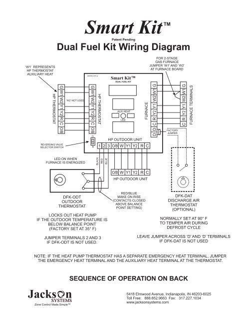
Smart Kit<br />
Patent Pending<br />
TM<br />
Dual Fuel Kit <strong>Wiring</strong> <strong>Diagram</strong><br />
‘W1’ REPRESENTS<br />
HP THERMOSTAT<br />
AUXILIARY HEAT<br />
HP THERMOSTAT<br />
G W1 W2 Y1 Y2 R C O/B<br />
REVERSING VALVE<br />
SELECTOR SWITCH<br />
‘W2’ NOT USED<br />
MODEL DFK-4<br />
G W1 W2 Y1 Y2 R C O/B<br />
O<br />
B<br />
HP THERMOSTAT<br />
Smart Kit<br />
DUAL FUEL KIT<br />
AUX HEAT<br />
LED<br />
HP OUTDOOR UNIT<br />
FURNACE<br />
1 2 3 O/B W Y1 Y2 R C<br />
FOR 2-STAGE<br />
GAS FURNACE<br />
JUMPER ‘W1’ AND ‘W2’<br />
AT FURNACE BOARD<br />
D D C R Y2 Y1 W2 W1 G<br />
FACTORY<br />
JUMPER<br />
C R Y2 Y1 W2 W1 G<br />
FURNACE TERMINALS<br />
LED ON WHEN<br />
FURNACE IS ENERGIZED<br />
BLACK<br />
RED<br />
BLUE<br />
O/B W Y1 Y2 R C<br />
HP OUTDOOR UNIT<br />
DFK-ODT<br />
OUTDOOR<br />
THERMOSTAT<br />
LOCKS OUT HEAT PUMP<br />
IF THE OUTDOOR TEMPERATURE IS<br />
BELOW BALANCE POINT<br />
(FACTORY SET AT 35° F)<br />
JUMPER TERMINALS 2 AND 3<br />
IF DFK-ODT IS NOT USED.<br />
RED/BLUE<br />
MAKE ON RISE<br />
(CONTACTS CLOSED<br />
ABOVE BALANCE<br />
POINT SETTING)<br />
DFK-DAT<br />
DISCHARGE AIR<br />
THERMOSTAT<br />
(OPTIONAL)<br />
NORMALLY SET AT 90° F<br />
TO TEMPER AIR DURING<br />
DEFROST CYCLE<br />
LEAVE JUMPER ACROSS ‘D’ AND ‘D’ TERMINALS<br />
IF DFK-DAT IS NOT USED<br />
NOTE: IF THE HEAT PUMP THERMOSTAT HAS A SEPARATE EMERGENCY HEAT TERMINAL, JUMPER<br />
THE EMERGENCY HEAT TERMINAL AND THE AUXILIARY HEAT TERMINAL AT THE THERMOSTAT.<br />
SEQUENCE OF OPERATION ON BACK<br />
Zone Control Made Simple<br />
5418 Elmwood Avenue, Indianapolis, IN 46203-6025<br />
Toll Free: 888.652.9663 Fax: 317.227.1034<br />
www.jacksonsystems.com
Smart Kit<br />
Patent Pending<br />
Dual Fuel Kit Sequence of Operation<br />
Outdoor temperature above outdoor thermostat setpoint (High Balance Point)<br />
2 Heat / 1 Cool<br />
When the space thermostat calls for heating and the outside temperature is above the setpoint (High Balance Point) of<br />
the outdoor thermostat (DFK-ODT), the heat pump will operate as first stage heat. If there is a call for second stage<br />
heat, or if the thermostat is placed in the emergency heat mode, the Smart Kit will automatically de-energize ‘Y1’ and<br />
energize ‘W1’. The furnace will then be brought on and will remain on until the thermostat call is satisfied.<br />
3 Heat / 2 Cool<br />
When the space thermostat calls for heating and the outside temperature is above the setpoint (High Balance Point) of<br />
the outdoor thermostat (DFK-ODT), the heat pump will operate as first stage heat. If there is a call for second stage<br />
heat, the second stage compressor will be energized. If there is a call for auxiliary heat, or if the thermostat is placed in<br />
the emergency heat mode, the Smart Kit will automatically de-energize ‘Y1’ and ‘Y2’ to the heat pump outdoor unit<br />
and energize ‘W1’. The furnace will then be brought on and will remain on until the thermostat call is satisfied.<br />
Outdoor temperature below outdoor thermostat setpoint (Low Balance Point)<br />
When the space thermostat calls for heating and the outside temperature falls below the setpoint (Low Balance Point)<br />
of the outdoor thermostat, the heat pump will be locked out and the furnace will become first stage heat. The furnace<br />
will remain energized until the thermostat call is satisfied.<br />
Cooling Mode<br />
When the space thermostat calls for cooling, the outdoor balance point is bypassed regardless of the outdoor<br />
temperature and only the heat pump will be energized.<br />
Reversing Valve<br />
It is important that the reversing valve selector switch located on the Smart Kit be set in the proper position. For heat<br />
pumps that energize the reversing valve in the cooling mode, set the selector switch to ‘O’. For heat pumps that<br />
energize the reversing valve in the heating mode, set the selector switch to ‘B’. Heat pump thermostats should also be<br />
configured in the same manner.<br />
Blower control<br />
The Smart Kit will stop the blower anytime it switches between heat pump and furnace operation and the blower will<br />
restart at the proper speed.<br />
DFK-DAT Discharge Air Thermostat<br />
An optional DFK-DAT discharge air thermostat can be connected to the ‘D’ and ‘D’ terminals on the Smart Kit board<br />
to limit the discharge air temperature during defrost cycle. (Typically used with an oil furnace) The sensor setpoint<br />
should be set at 90° F.<br />
DFK-ODT Outdoor Thermostat Specifications<br />
The DFK-ODT Outdoor Thermostat is a SPDT bi-metal outdoor rated thermostat. Temperature range is 0° F - 100° F<br />
with a 2° F heating and 3° F cooling differential. The device is UL Listed and CSA Certified.<br />
TM<br />
WIRING DIAGRAM ON FRONT<br />
Zone Control Made Simple<br />
5418 Elmwood Avenue, Indianapolis, IN 46203-6025<br />
Toll Free: 888.652.9663 Fax: 317.227.1034<br />
www.jacksonsystems.com<br />
06-1013-111308


