SVX4 User's Manual
SVX4 User's Manual
SVX4 User's Manual

Create successful ePaper yourself
Turn your PDF publications into a flip-book with our unique Google optimized e-Paper software.
FERMILAB-TM-2317-E<br />
Test Results for the <strong>SVX4</strong> Version A/B Chip D∅ Note 4251<br />
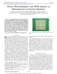
Ramp Scan<br />
160<br />
140<br />
Pedestal (ADC counts)<br />
120<br />
100<br />
80<br />
60<br />
40<br />
20<br />
CDF mode<br />
D0 mode<br />
0<br />
0 2 4 6 8<br />
Ramp range setting<br />
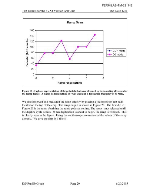
Figure 19 Graphical representation of the pedestals that were obtained by downloading all values for<br />
the Ramp Range. A Ramp Pedestal setting of 7 was used and a digitization frequency of 50 MHz.<br />
We also observed and measured the ramp directly by placing a Picoprobe on test pads<br />
located on the top of the chip. The ramp output is shown in Figure 20. The first dip in<br />
Figure 20 is the ramp obtaining the ramp pedestal setting. The ramp is not released until<br />
the digitize cycle occurs. When digitization is about to begin, the ramp is released. This<br />
is clearly seen in the figure. Using the oscilloscope, we measured the values of the ramp<br />
directly. We give the data in Table 8.<br />
D∅ RunIIb Group Page 20 6/20/2005