SVX4 User's Manual
SVX4 User's Manual
SVX4 User's Manual

Create successful ePaper yourself
Turn your PDF publications into a flip-book with our unique Google optimized e-Paper software.
FERMILAB-TM-2317-E<br />
Test Results for the <strong>SVX4</strong> Version A/B Chip D∅ Note 4251<br />
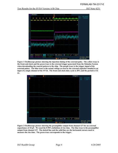
Figure 1 Oscilloscope picture showing the injection timing of the external pulse. The yellow trace is<br />
the front-end clock and the green trace is the external trigger generated from the Stimulus System<br />
when downloading the control pattern to the chip. The purple trace is the trigger signal of the<br />
external pulser. The blue trace is the actual voltage as seen by the external capacitor bonded to an<br />
input of a single channel of the <strong>SVX4</strong>. The front-end clock duty cycle is 28% and the period is 132<br />
ns.<br />
Figure 2 Oscilloscope picture showing the preamplifier output from channel 127 for an external<br />
capacitance of 10 pF. We used the 0-90% definition of rise time. The blue trace is the preamplifier<br />
output from channel 127. The dotted line and the solid line are the horizontal cursors used to<br />
measure the rise time. The green trace corresponds to the trigger.<br />
D∅ RunIIb Group Page 4 6/20/2005