Part III: Flare Reduction Project Family - IPIECA
Part III: Flare Reduction Project Family - IPIECA
Part III: Flare Reduction Project Family - IPIECA

You also want an ePaper? Increase the reach of your titles
YUMPU automatically turns print PDFs into web optimized ePapers that Google loves.
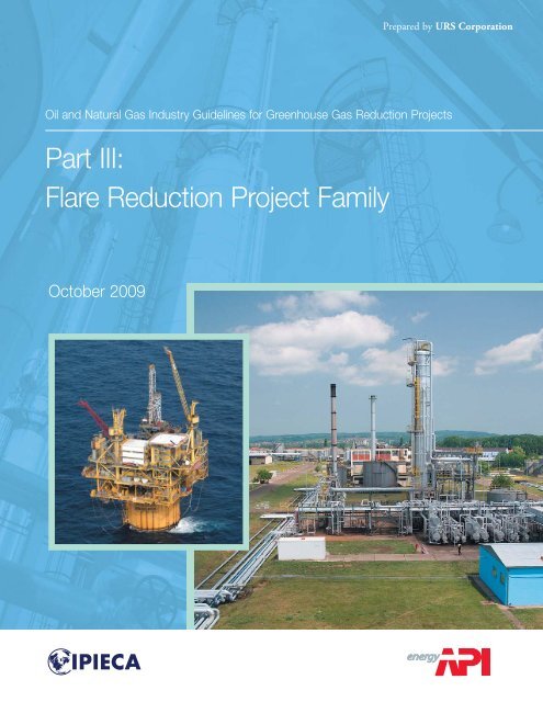
Prepared by URS Corporation<br />
Oil and Natural Gas Industry Guidelines for Greenhouse Gas <strong>Reduction</strong> <strong>Project</strong>s<br />
<strong>Part</strong> <strong>III</strong>:<br />
<strong>Flare</strong> <strong>Reduction</strong> <strong>Project</strong> <strong>Family</strong><br />
October 2009
International Petroleum Industry Environmental Conservation Association<br />
The International Petroleum Industry Environmental Conservation Association (<strong>IPIECA</strong>) was<br />
founded in 1974 following the establishment of the United Nations Environment Programme<br />
(UNEP). <strong>IPIECA</strong> provides one of the industry’s principal channels of communication with the<br />
United Nations.<br />
<strong>IPIECA</strong> is the single global association representing both the upstream and downstream oil and<br />
gas industry on key global environmental and social issues. <strong>IPIECA</strong>’s programme takes full<br />
account of international developments in these issues, serving as a forum for discussion and<br />
cooperation involving industry and international organizations.<br />
<strong>IPIECA</strong>’s aims are to develop and promote scientifically-sound, cost-effective, practical, socially<br />
and economically acceptable solutions to global environmental and social issues pertaining to the<br />
oil and gas industry. <strong>IPIECA</strong> is not a lobbying organization, but provides a forum for<br />
encouraging continuous improvement of industry performance.<br />
5th Floor, 209–215 Blackfriars Road, London SE1 8NL, United Kingdom<br />
Tel: +44 (0)20 7633 2388 Fax: +44 (0)20 7633 2389<br />
E-mail: info@ipieca.org Internet: www.ipieca.org<br />
American Petroleum Institute<br />
The American Petroleum Institute is the primary trade association in the United States<br />
representing the oil and natural gas industry, and the only one representing all segments of the<br />
industry. Representing one of the most technologically advanced industries in the world, API’s<br />
membership includes more than 400 corporations involved in all aspects of the oil and gas<br />
industry, including exploration and production, refining and marketing, marine and pipeline<br />
transportation and service and supply companies to the oil and natural gas industry.<br />
API is headquartered in Washington, D.C. and has offices in 27 state capitals and provides its<br />
members with representation on state issues in 33 states. API provides a forum for all segments<br />
of the oil and natural gas industry to pursue public policy objectives and advance the interests of<br />
the industry. API undertakes in-depth scientific, technical and economic research to assist in the<br />
development of its positions, and develops standards and quality certification programs used<br />
throughout the world. As a major research institute, API supports these public policy positions<br />
with scientific, technical and economic research. For more information, please visit www.api.org.<br />
1220 L Street NW, Washington DC, 20005-4070 USA<br />
Tel: +1 202 682 8000 Internet: www.api.org<br />
© <strong>IPIECA</strong> 2009. All rights reserved. No part of this publication may be reproduced, stored in a retrieval system, or transmitted in<br />
any form or by any means, electronic, mechanical, photocopying, recording or otherwise, without the prior consent of <strong>IPIECA</strong>.<br />
Cover photographs reproduced courtesy of the following:<br />
Xxxxxx (left): Copyright © Xxxxxxxxxxxxxxxxxxxxxxx.<br />
Xxxxxx (right): Copyright © Xxxxxxxxxxxxxxxxxxxxxxx.
Table of Contents<br />
PART I 1 .................................................................................................. March 2007<br />
Section 1. Introduction<br />
Section 2. GHG <strong>Reduction</strong> <strong>Project</strong> Concepts and Principles<br />
Section 3. Policy Considerations<br />
Section 4. Overview of GHG <strong>Reduction</strong> <strong>Project</strong> Families<br />
Section 5. Cogeneration <strong>Project</strong> <strong>Family</strong><br />
PART II 2 .................................................................................................... June 2007<br />
Section 6. Carbon Capture and Geological Storage Emission <strong>Reduction</strong> <strong>Project</strong><br />
<strong>Family</strong><br />
PART <strong>III</strong> ............................................................................................... October 2009<br />
Section 7. <strong>Flare</strong> <strong>Reduction</strong> <strong>Project</strong> <strong>Family</strong> .............................................................. 1<br />
7.1 Overview ........................................................................................................................1<br />
7.2 Introduction ....................................................................................................................1<br />
7.3 <strong>Project</strong> Definition ...........................................................................................................3<br />
7.3.1 Extraction and Production..................................................................................5<br />
7.3.2 Processing ..........................................................................................................5<br />
7.3.3 Refining..............................................................................................................6<br />
7.3.4 Transport, Storage, and Distribution ..................................................................6<br />
7.4 Baseline Scenarios .........................................................................................................6<br />
7.5 Emission Sources and Assessment Boundary ................................................................7<br />
7.6 <strong>Project</strong> Emission <strong>Reduction</strong>s .......................................................................................10<br />
7.7 Monitoring ...................................................................................................................10<br />
7.8 Reporting and Documentation .....................................................................................11<br />
7.9 Verification/Assurance ................................................................................................11<br />
7.10 Technical Considerations .............................................................................................11<br />
7.11 Policy Considerations ..................................................................................................12<br />
7.12 <strong>Project</strong> Examples .........................................................................................................12<br />
7.12.1 Associated Gas Recovery for Processing and Sales ........................................12<br />
7.12.2 Associated Gas Recovery for Re-injection and Utilization .............................13<br />
7.12.3 Utilizing a Small <strong>Flare</strong> Gas Stream for On-Site Power Generation ................13<br />
7.13 Conclusions ..................................................................................................................13<br />
7.14 References ....................................................................................................................14<br />
1 International Petroleum Industry Environmental Conservation Association (<strong>IPIECA</strong>) and American Petroleum<br />
Institute (API). Oil and Natural Gas Industry Guidelines for Greenhouse Gas <strong>Reduction</strong> <strong>Project</strong>s, March 2007.<br />
2 <strong>IPIECA</strong> and API. Oil and Natural Gas Industry Guidelines for Greenhouse Gas <strong>Reduction</strong> <strong>Project</strong>s, <strong>Part</strong> II:<br />
Carbon Capture and Geological Storage Emission <strong>Reduction</strong> <strong>Project</strong> <strong>Family</strong>, June 2007.<br />
October 2009<br />
i
Attachments<br />
Attachment 1 <strong>Flare</strong> <strong>Reduction</strong> <strong>Project</strong> <strong>Family</strong> Case Study #1:<br />
Gas Recovery for Local and International Sale .....................................................18<br />
Attachment 1 <strong>Flare</strong> <strong>Reduction</strong> <strong>Project</strong> <strong>Family</strong> Case Study #2:<br />
Gas Recovery for Reinjection and Utilization for Power Generation ...................30<br />
Attachment 1 <strong>Flare</strong> <strong>Reduction</strong> <strong>Project</strong> <strong>Family</strong> Case Study #3:<br />
Recovery of <strong>Flare</strong> Gas and Utilization for On-site Power Generation ..................42<br />
Attachment 2 CDM <strong>Project</strong> Methodologies Involving <strong>Flare</strong> <strong>Reduction</strong> ......................................56<br />
List of Tables<br />
Table 7-1. EIA Top Twenty Gas Flaring Countries for 2006 ....................................................... 2<br />
Table 7-2. World Bank Estimated Top Twenty Gas Flaring Countries ........................................ 3<br />
Table 7-3. Candidate Baseline Conditions for Probable <strong>Flare</strong> <strong>Reduction</strong> <strong>Project</strong>s at<br />
Oil Production Facilities (Bold italic text indicates the project activity) .................... 7<br />
Table 7-4. Summary of Potential GHG Emission Sources ........................................................... 8<br />
Table 7-5. Case Study #1 Baseline Scenarios Assessment ......................................................... 20<br />
Table 7-6. Case Study #1 Assessment Boundary Determination ................................................ 23<br />
Table 7-7. Case Study #2 Baseline Scenario Assessment ........................................................... 32<br />
Table 7-8. Case Study #2 Assessment Boundary Determination ................................................ 35<br />
Table 7-9. Case Study #3 Baseline Scenario Assessment ........................................................... 44<br />
Table 7-10. Case Study #3 Assessment Boundary Determination ................................................ 47<br />
Table 7-11. Applicability and History of Approved CDM Baseline Methodologies<br />
for <strong>Flare</strong> <strong>Reduction</strong> <strong>Project</strong>s ...................................................................................... 57<br />
List of Figures<br />
Figure 7-1. Natural Gas and Oil Industry Value Chain .................................................................. 4<br />
Figure 7-2. <strong>Project</strong> Illustration for Case Study #1 - <strong>Flare</strong> Gas Recovery in a<br />
Gas Processing Plant .................................................................................................. 18<br />
Figure 7-3. Baseline Illustration for Case Study #1...................................................................... 22<br />
Figure 7-4. <strong>Project</strong> Assessment Boundary for Case Study #1...................................................... 22<br />
Figure 7-5. Baseline Illustration for Case Study #2...................................................................... 33<br />
Figure 7-6. <strong>Project</strong> Assessment Boundary for Case Study #2...................................................... 34<br />
Figure 7-7. Baseline Illustration for Case Study #3...................................................................... 45<br />
Figure 7-8. <strong>Project</strong> Assessment Boundary for Case Study #3 ...................................................... 46<br />
October 2009<br />
ii
Section 7. <strong>Flare</strong> <strong>Reduction</strong> <strong>Project</strong> <strong>Family</strong><br />
SECTION 7.<br />
FLARE REDUCTION PROJECT FAMILY<br />
7.1 Overview<br />
This section is a continuation of the Oil and Natural Gas Industry Guidelines for Greenhouse<br />
Gas <strong>Reduction</strong> <strong>Project</strong>s (<strong>IPIECA</strong> and API, 2007), referred to as the General <strong>Project</strong> Guidelines.<br />
It is the third greenhouse gas (GHG) reduction “project family” in an ongoing process of<br />
developing guidelines for project activities of interest to the oil and natural gas industry.<br />
This project family addresses GHG emission reductions associated with reduced flaring activities<br />
from oil and natural gas operations. Guidelines are provided following the framework presented<br />
in Section 2 of the General <strong>Project</strong> Guidelines (<strong>IPIECA</strong> and API, 2007). The focus is on specific<br />
technical considerations and aspects rather than policy considerations. Case studies of three<br />
potential applications are provided in Attachment 1.<br />
7.2 Introduction<br />
<strong>Flare</strong>s are important safety and emission control devices in the oil and natural gas industry.<br />
Flaring, which combusts hydrocarbon gas streams, is necessary to prevent uncontrolled releases<br />
to the atmosphere and to relieve dangerous equipment overpressure conditions. Flaring is<br />
generally preferable, in terms of both safety and GHG emission considerations, to venting, i.e.,<br />
the release of uncombusted gas to the atmosphere.<br />
The most recent data reported by the Energy Information Administration (EIA) indicate that<br />
approximately 97×10 9 cubic meters (m 3 ) [3.4×10 12 cubic feet (ft 3 )] of natural gas are flared<br />
annually, or about 2.7 percent of all natural gas production worldwide. 3 This flared gas is<br />
equivalent to almost 15 percent of the annual natural gas consumption in the U.S. The EIA also<br />
estimates that the U.S. flares or vents only about 0.55 percent of its gross natural gas production<br />
and about 3.8 percent of the total amount of natural gas flared and vented worldwide. As shown<br />
in Table 7-1, the top 20 countries accounted for the flaring of 86.1 billion cubic meters, which is<br />
over 88 percent of the total flaring in the world in 2006. 3<br />
<strong>Flare</strong>d gas is not tracked separately from vented gas within the U.S. oil and natural gas<br />
production sector. The states voluntarily report monthly combined volumes of natural gas<br />
vented and flared using Form EIA-895A. EIA then reports all of this as flared gas in compiling<br />
its annual GHG inventories. Venting volumes are not included in the data for other countries<br />
listed in Table 7-1.<br />
3 Energy Information Administration, August 22, 2008.<br />
http://www.eia.doe.gov/international/RecentNaturalGasProductionAllTypes.xls<br />
October 2009 1
Section 7. <strong>Flare</strong> <strong>Reduction</strong> <strong>Project</strong> <strong>Family</strong><br />
Rank<br />
Table 7-1. EIA Top Twenty Gas Flaring Countries for 2006<br />
Country<br />
2006 Gross Natural<br />
Gas Production<br />
10 9 cubic meters<br />
2006 <strong>Flare</strong>d<br />
Volume,<br />
10 9 cubic meters<br />
Approximate CO 2<br />
Emissions from Flaring<br />
(10 6 tonnes /year)*<br />
1 Nigeria 61.80 22.3 53.2<br />
2 Iran 168.50 12.5 29.8<br />
3 Iraq 11.90 7.7 18.4<br />
4 Angola 9.40 6.5 15.5<br />
5 Indonesia 83.67 4.4 10.5<br />
6 United States ** 665.64 3.7 8.8<br />
7 Algeria 193.60 3.3 7.9<br />
8 Venezuela 53.00 3.2 7.6<br />
9 Qatar 62.00 3.1 7.4<br />
10 Mexico 51.81 2.5 6.0<br />
11 Congo (Brazzaville) 7.50 2.2 5.2<br />
12 Canada 220.43 2.1 5.0<br />
13 Cameroon 1.96 1.9 4.6<br />
14 Malaysia 82.60 1.9 4.5<br />
15 Brazil 17.71 1.9 4.4<br />
16 United Kingdom 86.36 1.5 3.7<br />
17 Oman 29.78 1.4 3.4<br />
18 Germany 21.00 1.4 3.3<br />
19 Trinidad and<br />
40.13 1.4<br />
Tobago<br />
3.2<br />
20 Equatorial Guinea 3.80 1.2 2.9<br />
Total for the Top 20<br />
Countries<br />
1,873 86.1 205.4<br />
Global Total 3,618 97.1 231.4<br />
* For comparison purposes, CO 2 emissions have been estimated using the API Compendium default natural gas higher<br />
heating value of 1235 Btu/ft 3 (raw, unprocessed gas) (Compendium Table 3-8) and the emission factor of 0.0547 tonnes<br />
CO 2 /MMBtu for flared natural gas (Compendium Table 4-3).<br />
** Data for the United States includes an undifferentiated volume of vented gas. Many countries other than the U.S. (e.g.,<br />
Indonesia and Venezuela) are known to vent significant volumes of gas, but these vented gas volumes are not included in<br />
the above table.<br />
Source: Energy Information Administration, “World Natural Gas Production, Most Recent Estimates, 2006,” August 22,<br />
2008.<br />
The annual 2006 GHG inventory report compiled by EIA for the U.S. attributes 7.8 million<br />
tonnes 4 of CO 2 emissions to “natural gas flaring,” which is defined as gas disposed of by burning<br />
in flares, usually at the production sites or at gas processing plants (EIA, 2008). This accounts<br />
for approximately 87% of the total flaring (and venting) emissions listed for the U.S. in Table<br />
7 - 1, providing a strong indication that flaring and venting at oil and gas production sites is the<br />
dominant type of flaring in the U.S.<br />
As a comparison to the EIA data, Table 7-2 presents data on the top 20 flaring countries as<br />
reported by the World Bank based on satellite data.<br />
4 tonnes = 1000 kg<br />
October 2009 2
Section 7. <strong>Flare</strong> <strong>Reduction</strong> <strong>Project</strong> <strong>Family</strong><br />
Table 7-2. World Bank Estimated Top Twenty Gas Flaring Countries<br />
<strong>Flare</strong>d Volume, 10 9 cubic meters Approximate CO 2 Emissions<br />
Rank* Country 2005 2006 2007<br />
from Flaring (10 6<br />
tonnes/year) for 2006 **<br />
1 Russia 55.2 48.8 50.0 116.4<br />
2 Nigeria 21.3 19.3 16.8 46.0<br />
3 Iran 1.3 12.1 10.6 28.9<br />
4 Iraq 7.1 7.4 7.0 17.7<br />
5 Kazakhstan 5.8 6.0 5.3 14.3<br />
6 Algeria 5.2 6.2 5.2 14.8<br />
7 Libya 4.4 4.3 3.7 10.3<br />
8 Angola 4.6 4.0 3.5 9.5<br />
9 Saudi Arabia 3.0 3.3 3.4 7.9<br />
10 Qatar 2.7 2.8 2.9 6.7<br />
11 China 2.8 2.8 2.5 6.7<br />
12 Indonesia 2.7 3.0 2.4 7.2<br />
13 Kuwait 2.5 2.5 2.1 6.0<br />
14 Venezuela 2.1 2.0 2.1 4.8<br />
15 Uzbekistan 2.5 2.8 2.0 6.7<br />
16 United States 2.0 1.9 1.9 4.5<br />
17 Oman 2.5 2.2 1.9 5.2<br />
18 Mexico 0.9 1.2 1.7 2.9<br />
19 Malaysia 1.7 1.8 1.7 4.3<br />
20 Gabon 2.2 1.9 1.6 4.5<br />
Total for the Top 20<br />
Countries<br />
142 136 128 325.2<br />
Global Flaring Level 162 157 147 374.5<br />
* Rankings shown are based on 2007 data.<br />
** CO 2 emissions have been estimated using the API Compendium default natural gas higher heating value of 1235 Btu/ft 3 (raw,<br />
unprocessed gas) (Compendium Table 3-8) and the emission factor of 0.0547 tonnes CO 2 /MMBtu for flared natural gas<br />
(Compendium Table 4-3).<br />
Source: http://go.worldbank.org/G2OAW2DKZ0<br />
The World Bank’s worldwide flared gas estimate for 2006 is 60×10 9 m 3 (2.1×10 12 ft 3 ) higher<br />
than that provided by EIA, resulting in an additional 143×10 6 tonnes of CO 2 emissions. The<br />
World Bank’s flare estimate for the U.S. based on satellite data is only about one-half of the<br />
corresponding EIA estimate. The likely explanation for this discrepancy is that the EIA data for<br />
the U.S. are known to include vented volumes, which would not be detected by the satellite<br />
measurements. The countries included in the top 20 also differ between the two lists, indicating<br />
some important data gaps in the EIA information.<br />
7.3 <strong>Project</strong> Definition<br />
<strong>Flare</strong> reduction projects impact the natural gas and oil value chain. As illustrated in Figure 7-1,<br />
this chain consists of production and processing; refining; transport, storage, and distribution.<br />
October 2009 3
Section 7. <strong>Flare</strong> <strong>Reduction</strong> <strong>Project</strong> <strong>Family</strong><br />
Figure 7-1. Natural Gas and Oil Industry Value Chain<br />
The best opportunities for flare reduction projects are in the oil production and refining sectors of<br />
the industry. However, flaring at refineries is generally limited and, in developed countries,<br />
closely regulated. Thus, this guidance document focuses on upstream operations. Opportunities<br />
to eliminate continuous flaring of associated gas at oil production sites in some parts of the world<br />
have enabled several projects to be implemented that have achieved very large GHG emission<br />
reductions. For example, eight flare reduction projects at oil production operations have been<br />
registered to date for carbon credit generation under the Clean Development Mechanism (CDM)<br />
provisions of the Kyoto Protocol. 5<br />
5 http://cdm.unfccc.int/<strong>Project</strong>s/projsearch.html. Six projects have been registered under methodology AM0009;<br />
two have been registered under methodology AM0037.<br />
October 2009 4
Section 7. <strong>Flare</strong> <strong>Reduction</strong> <strong>Project</strong> <strong>Family</strong><br />
Notwithstanding the fact that larger flare reduction projects are probably of greatest interest from<br />
the perspective of generating carbon credits, companies may also wish to consider smaller<br />
projects for other reasons, such as utilization of an otherwise wasted energy source or to comply<br />
with an internal policy to decrease the carbon footprint of a company or business unit. Two flare<br />
reduction projects of this type have been registered for CDM carbon credit generation at<br />
petroleum refineries. 6 In certain cases, utilization of waste gas rather than flaring can represent<br />
an economically attractive option, even without consideration of potential carbon credits.<br />
Accordingly, these types of projects are also addressed in this section.<br />
Venting also occurs primarily in the production sector, because this activity is regulated to low<br />
levels or eliminated at most U.S. refineries. Although, as noted above, separate flaring and<br />
venting statistics are not maintained by the U.S. federal government, flaring probably is used<br />
much more commonly in this country than venting. Flaring of gas is preferable to venting from<br />
the standpoint of the GHG emissions perspective given that the global warming potential of<br />
methane (CH 4 ) is 21 times that for CO 2 .<br />
7.3.1 Extraction and Production<br />
The production of crude oil may also produce natural gas, referred to as associated gas. 7 If the<br />
crude is produced in an area that lacks either a natural gas infrastructure or a market for the<br />
natural gas, the associated gas may be vented or flared.<br />
Potential types of flare reduction projects in the upstream sector include measures to avoid<br />
routine flaring of associated gas, reduction in venting of associated gas, or reduction in nonroutine<br />
gas flaring. Greenhouse gas emission reductions result when associated gas is captured<br />
for energy use, reducing CH 4 emissions where the gas was previously vented or reducing CO 2<br />
emissions where other fuel streams are replaced with the previously flared gas. A flare reduction<br />
project may also decrease GHG emissions through the capture and underground injection of the<br />
associated gas for long-term isolation from the atmosphere or for enhanced oil recovery. A<br />
number of projects involving re-injection and recovery of previously flared or vented associated<br />
gas streams have been implemented in the last several years. Some of these projects have<br />
included subsequent use of the recovered gas as feedstock for gas processing plants or as fuel for<br />
power plants. Several such projects have resulted in the award of carbon credits under the CDM<br />
program.<br />
7.3.2 Processing<br />
<strong>Flare</strong>s are used at natural gas processing facilities to handle emergency releases of gas and to<br />
ensure safe plant shut-downs and start-ups. Gas processing flares are also used as emission<br />
control devices to eliminate venting of waste gas streams from sweetening and dehydration<br />
equipment. In this context, flares are an integral part of a gas plant’s operation and are designed<br />
6 http://cdm.unfccc.int/<strong>Project</strong>s/projsearch.html. Methodology AMS-<strong>III</strong>.P.<br />
7 Associated gas is defined as natural gas that is found in association with crude oil, either dissolved in the oil or as a<br />
cap of free gas above the oil.<br />
October 2009 5
Section 7. <strong>Flare</strong> <strong>Reduction</strong> <strong>Project</strong> <strong>Family</strong><br />
to be used routinely. Introduction of a flare to combust a gas stream that would otherwise be<br />
vented to the atmosphere could be a candidate project for reducing GHG emissions by virtue of<br />
the lower global warming potential of CO 2 versus that of CH 4 .<br />
7.3.3 Refining<br />
<strong>Flare</strong>s are necessary for the safe disposal of gas streams generated within oil refineries. The<br />
refinery blowdown system gathers relief gas from various refinery process units; separates liquid<br />
from vapors; recovers any condensable oil and water; and recovers gases for use in the refinery<br />
fuel gas system. When the heating value of a recovered gas stream is insufficient to use as<br />
refinery fuel or when, as sometimes occurs during upsets, the volume of gas exceeds the<br />
refinery’s capacity for its recovery and use as a fuel, the blowdown system routes the vapors to<br />
the flare (BAAQMD, 2005). The units most likely to contribute to flaring are the crude unit, the<br />
fluid catalytic cracking unit (FCCU), and the coker (RTI International, 2007).<br />
Opportunities for reduced flaring at refineries include:<br />
• Using flare gas recovery systems for routine venting and planned shutdowns;<br />
• Improving operator training and better documentation procedures, highlighting<br />
environmental impacts, and allowing additional time for process unit start-ups and shutdowns;<br />
and<br />
• Reducing flaring among ethylene producers by recycling off-spec streams to furnace<br />
feed, augmenting the plant’s steam capacity, or using a ground flare to handle off-spec<br />
and start-up loads (Industry Professionals for Clean Air, 2005).<br />
As mentioned previously, two projects have been registered by the CDM Executive Board for<br />
flare reduction projects at refineries. In addition, an approved methodology for quantifying the<br />
baseline and project emissions from such projects also exists (AM0055).<br />
7.3.4 Transport, Storage, and Distribution<br />
For natural gas transport, storage, and distribution facilities, flares may be used for emergency<br />
releases of natural gas and to handle blowdown volumes associated with maintenance of large<br />
compressor stations, storage facilities, or metering and pressure regulating stations. Since such<br />
flares are used primarily for temporary service under certain conditions, the corresponding<br />
amounts of potential emission reductions are generally smaller than for an industry sector like<br />
Extraction and Production that uses flares continuously.<br />
7.4 Baseline Scenarios<br />
Candidate baseline scenarios for flare reduction projects represent operations or conditions that<br />
would have occurred in the absence of such projects. A list of potential baseline scenarios for<br />
the most probable flare reduction projects (i.e., at oil production operations) is provided in<br />
Table 7-3.<br />
October 2009 6
Section 7. <strong>Flare</strong> <strong>Reduction</strong> <strong>Project</strong> <strong>Family</strong><br />
Table 7-3. Candidate Baseline Conditions for Probable <strong>Flare</strong> <strong>Reduction</strong> <strong>Project</strong>s<br />
at Oil Production Facilities<br />
(Bold italic text indicates the project activity)<br />
Probable <strong>Project</strong> Elements<br />
Gas recovery options for flare gas reduction:<br />
• Natural gas supply for on-site energy use<br />
• Gas recovery and transport to supply local energy<br />
markets<br />
• Gas recovery for LNG export markets or international<br />
pipelining to targeted domestic or international<br />
markets<br />
• Gas separation and liquefied petroleum gas (LPG)<br />
recovery for markets, possibly in conjunction with reinjection<br />
of the stripped (dry) gas into the petroleum<br />
reservoir.<br />
Candidate Baseline Scenarios<br />
• Gas is vented to the atmosphere<br />
• Gas is flared<br />
• Gas is recovered for use as a fuel<br />
Gas compression and re-injection into an oil or gas reservoir 8 • Gas is vented to the atmosphere<br />
• Gas is flared<br />
• Gas is re-injected for storage<br />
(differentiated from gas recovery and<br />
use)<br />
Gas lift for improved oil recovery 8 • Gas is vented to the atmosphere<br />
• Gas is flared<br />
• Gas is re-injected into the reservoir<br />
for improved oil recovery<br />
7.5 Emission Sources and Assessment Boundary<br />
As discussed in Section 2.5 of the General <strong>Project</strong> Guidelines (<strong>IPIECA</strong> and API, 2006), the<br />
assessment boundary encompasses all project and baseline emission sources that are controlled<br />
by the project proponent, that are related to the project, or that are affected by the flare reduction<br />
project. The assessment boundary can vary even among projects with similar emission reduction<br />
approaches, depending on which sources are controlled or have been invested in by the project<br />
proponent. Different emission sources that may be associated with a flare reduction project are<br />
summarized in Table 7-4.<br />
8 Note that no baseline methodology has yet been approved for gas lift projects under the CDM program.<br />
October 2009 7
Section 7. <strong>Flare</strong> <strong>Reduction</strong> <strong>Project</strong> <strong>Family</strong><br />
Table 7-4. Summary of Potential GHG Emission Sources<br />
Stage in Gas<br />
Chain<br />
Extraction and<br />
Production<br />
Gas Recovery<br />
Gas Processing,<br />
Storage,<br />
Transport, and<br />
Distribution<br />
Controlled,<br />
Emission Source<br />
Emission<br />
Type*<br />
Related or<br />
Affected GHG Species<br />
Emissions from stationary Combustion Controlled<br />
combustion sources<br />
Primarily CO<br />
associated with the extraction<br />
2 ; CH 4 and<br />
N<br />
of crude oil<br />
2 O to lesser degree<br />
Flaring of associated gas Combustion Controlled<br />
Consumption of other fuels Combustion Controlled Primarily CO 2 ; CH 4 and<br />
in place of the associated gas<br />
N 2 O to lesser degree<br />
Venting of associated gas Vented Controlled CH 4 ; potentially some<br />
CO 2<br />
Fugitive emissions from Fugitive Controlled CH 4 ; potentially some<br />
equipment associated with<br />
CO 2<br />
the extraction of crude oil<br />
Process emissions from gas<br />
handling operations,<br />
maintenance or emergency<br />
releases of gas associated<br />
with the extraction of crude<br />
oil<br />
Vented Controlled CH 4 ; potentially some<br />
CO 2<br />
Mobile source energy<br />
consumption<br />
Combustion Controlled Primarily CO 2 ; CH 4 and<br />
N 2 O to lesser degree<br />
Purchased electricity Indirect Related Primarily CO 2 ; CH 4 and<br />
N 2 O to lesser degree<br />
Emissions from stationary Combustion Controlled Primarily CO 2 ; CH 4 and<br />
combustion sources<br />
N 2 O to lesser degree<br />
associated with the separation<br />
of associated gas from crude<br />
oil<br />
Fugitive emissions from gas<br />
handling equipment<br />
associated with the separation<br />
of associated gas from crude<br />
oil<br />
Process emissions from gas<br />
handling operations,<br />
maintenance or emergency<br />
releases of gas<br />
Fugitive Controlled CH 4 ; potentially some<br />
CO 2<br />
Vented Controlled CH 4 ; potentially some<br />
CO 2<br />
Mobile source energy<br />
consumption<br />
Combustion Controlled Primarily CO 2 ; CH 4 and<br />
N 2 O to lesser degree<br />
Purchased electricity Indirect Related Primarily CO 2 ; CH 4 and<br />
N 2 O to lesser degree<br />
Emissions from stationary Combustion Controlled Primarily CO 2 ; CH 4 and<br />
combustion sources<br />
N 2 O to lesser degree<br />
associated with gas<br />
processing and transport<br />
October 2009 8
Section 7. <strong>Flare</strong> <strong>Reduction</strong> <strong>Project</strong> <strong>Family</strong><br />
Stage in Gas<br />
Chain<br />
Gas Processing,<br />
Storage,<br />
Transport, and<br />
Distribution,<br />
continued<br />
End-Use<br />
Table 7-4. Summary of Potential GHG Emission Sources, continued<br />
Emission Source<br />
Fugitive emissions from gas<br />
handling equipment<br />
associated with gas<br />
processing, intermediate<br />
storage, and transport<br />
Process emissions from gas<br />
handling operations,<br />
intermediate storage,<br />
maintenance or emergency<br />
releases of gas associated with<br />
gas processing and transport<br />
Fugitive emissions<br />
Loading/unloading of LNG or<br />
LPG<br />
Mobile source energy<br />
consumption<br />
Emission<br />
Type*<br />
Controlled,<br />
Related or<br />
Affected<br />
GHG Species<br />
Fugitive Controlled CH 4 ; potentially some CO 2<br />
Vented Controlled CH 4 ; potentially CO 2<br />
Fugitive Controlled CH 4<br />
Combustion Controlled Primarily CO 2 ; CH 4 and<br />
N 2 O to lesser degree<br />
Purchased electricity Indirect Related Primarily CO 2 ; CH 4 and<br />
Combustion emissions<br />
associated with re-injection of<br />
the gas for disposal or for<br />
enhanced oil recovery<br />
Combustion emissions<br />
associated with end-use of<br />
associated gas<br />
Fugitive emissions from gas<br />
handling equipment associated<br />
with end use operations<br />
Process emissions from gas<br />
handling equipment associated<br />
N 2 O to lesser degree<br />
Combustion Controlled Primarily CO 2 ; CH 4 and<br />
N 2 O to lesser degree<br />
Combustion<br />
Fugitive<br />
Vented<br />
Potentially<br />
Related or<br />
Affected<br />
Potentially<br />
Related or<br />
Affected<br />
Potentially<br />
Related or<br />
Affected<br />
Primarily CO 2 ; CH 4 and<br />
N 2 O to lesser degree<br />
CH 4 ; potentially some CO 2<br />
CH 4 ; potentially CO 2<br />
with end use operations<br />
* Indirect emissions are “Related” emission sources. All others may be “Controlled” or “Related” depending on which sources<br />
the project proponent controls.<br />
The assessment boundary may include combustion, venting, and fugitive emissions associated<br />
with oil and gas extraction, as well as capture and processing of the previously flared or vented<br />
gas. Emissions from transport and distribution infrastructure facilities that are part of the project<br />
investment would also be included in the assessment boundary, e.g., compression of recovered<br />
gas transported via pipeline to receiving facilities or points of sale, fugitive emissions from<br />
pipeline components, and venting of pipelines during maintenance activities.<br />
A few projects that use previously flared gas as a feedstock for production of chemicals have<br />
been successfully registered under the CDM program. However, emissions related to the<br />
combustion of recovered natural gas at off-site locations generally have not been included within<br />
the project boundary for crediting purposes (for example, see CDM Approved Methodology<br />
0009). Although conceptually it should be possible to include emissions associated with<br />
combustion of recovered gas from a flare reduction project for electric power generation, no<br />
October 2009 9
Section 7. <strong>Flare</strong> <strong>Reduction</strong> <strong>Project</strong> <strong>Family</strong><br />
methodology for doing so has yet been approved by the CDM Executive Board. Thus, obtaining<br />
CDM credits for use of previously-flared gas to replace a more carbon-intensive fuel at a power<br />
plant would require development and approval of a new methodology. 9<br />
7.6 <strong>Project</strong> Emission <strong>Reduction</strong>s<br />
Emissions reductions are the net difference between the baseline emissions and project<br />
emissions. Emissions reductions are typically reported in terms of carbon dioxide equivalents<br />
(CO 2 e), in which all of the GHG species are converted to an equivalent basis by weighting the<br />
mass emission contribution of each species by its global warming potential (GWP) relative to<br />
that of CO 2 . For example, the GWP for CH 4 is 21 times higher than that for CO 2 . The<br />
calculation of potential emission reductions for different categories of flare reduction projects is<br />
demonstrated by means of three examples presented in Attachment 1.<br />
In quantifying project emission reductions, baseline emissions should reflect emission sources<br />
associated with each step of the gas chain that would have occurred in the absence of the project.<br />
This can be expressed by the following general equation:<br />
Baseline Emissions = CMB 1 + VENT 1 + FUG 1 + IND 1 (Equation 1)<br />
where:<br />
CMB 1 = Direct combustion emissions that would have occurred in the baseline scenario;<br />
VENT 1 = Vented GHG emissions from baseline operations or equipment that would have<br />
occurred in the baseline scenario;<br />
FUG 1 = Fugitive GHG emissions from baseline equipment that would have occurred in<br />
the baseline scenario; and<br />
IND 1 = Indirect emissions that would have occurred due to electricity purchased from<br />
outside sources in the baseline scenario.<br />
Similarly, project emissions can be expressed as:<br />
<strong>Project</strong> Emissions = CMB 2 + VENT 2 +FUG 2 + IND 2 (Equation 2)<br />
where CMB 2 , VENT 2 , FUG 2 , and IND 2 refer to combustion, vented, fugitive, and indirect<br />
emissions, respectively, associated with the project being considered.<br />
7.7 Monitoring<br />
Monitoring for a flare reduction project is necessary to establish and document the resulting<br />
GHG emissions reduction. Monitoring refers to the continuous or periodic measurement and/or<br />
9 One possible approach would be to propose a combination of two previously approved methodologies, such as<br />
AM0009 for flare reduction projects and ACM0011 for fuel switching projects. Detailed information on all<br />
approved methodologies, as well as successful and unsuccessful attempts to modify them can be found on the main<br />
CDM website at http://cdm.unfccc.int/index.html.<br />
October 2009 10
Section 7. <strong>Flare</strong> <strong>Reduction</strong> <strong>Project</strong> <strong>Family</strong><br />
recording of parameter values needed to quantify actual emissions and emission reductions from<br />
the project relative to the baseline scenario.<br />
Monitoring for a flare reduction project may include the following:<br />
• Measurement of the composition and quantity of associated gas recovered;<br />
• Estimation of emissions associated with operations or processes along the gas value<br />
chain;<br />
• Measurement of the composition and quantity of other fuels replaced by associated gas as<br />
part of a project activity; and<br />
• Measurement of the quantity of associated gas or gas products consumed or transferred to<br />
other parties.<br />
7.8 Reporting and Documentation<br />
Section 2 of the General <strong>Project</strong> Guidelines provides the following high-level objectives for<br />
emission reduction reporting and documentation:<br />
• Provide sufficient transparency to enable the intended audience to make an informed<br />
decision on the validity of the emission reductions;<br />
• Provide a plausible and transparent accounting of the project decisions and assumptions;<br />
and<br />
• Maintain supporting documentation.<br />
These general principles also apply to reporting in support of emission reductions from flare<br />
reduction projects.<br />
7.9 Verification/Assurance<br />
Verification involves an assessment to provide confirmation that the project and its associated<br />
emission reductions have not been materially misstated. This largely entails evaluating the<br />
implementation of the approved monitoring methodology against reported project and baseline<br />
emissions. On the basis of the verification activities, a conclusion is reached as to whether the<br />
data within the emissions report contain any omissions, misrepresentation, or errors that would<br />
lead to a material misstatement of the reported information. As stated in Section 2 of the General<br />
<strong>Project</strong> Guidelines (<strong>IPIECA</strong> and API, 2006), verification should focus on quality assurance with<br />
the objective of improving the overall reliability of the reported emission reductions.<br />
Verification should provide the user with assurance that the reported emission reductions are<br />
credible.<br />
7.10 Technical Considerations<br />
Some technical issues and challenges associated with implementing a flare reduction project may<br />
warrant consideration. These include, but are not limited to, the following elements:<br />
• Gas re-injection technical considerations:<br />
− Reservoir suitability for gas re-injection and long-term storage;<br />
− Possible detrimental impacts on oil production due to gas re-injection;<br />
October 2009 11
Section 7. <strong>Flare</strong> <strong>Reduction</strong> <strong>Project</strong> <strong>Family</strong><br />
− Use of re-injection for gas lift purposes;<br />
− Fuel usage requirements and GHG emissions (combustion, vented and fugitive) from<br />
equipment used to re-inject and recover CO 2 from produced oil and comparison of<br />
these emissions relative to those associated with the flaring option;<br />
• Limitations to on-site energy needs, limitations in gas-liquid fraction, etc.; and<br />
• Estimated remaining life of the producing reservoir.<br />
7.11 Policy Considerations<br />
The following policy issues should be noted and may impact the ability to receive credit for a<br />
flare reduction project:<br />
• Government regulations and policies to prohibit routine gas venting and/or flaring appear<br />
to be gaining increased support in certain countries and may affect whether continued<br />
flaring can be considered a viable baseline scenario in the future;<br />
• Potential barriers that would prevent or reduce the likelihood of the project or other<br />
baseline scenarios could include situations such as:<br />
− Complex commercial situation for marketing associated gas due to multiple<br />
stakeholder involvement in joint venture partnerships, third party operators,<br />
government, infrastructure owners, etc.;<br />
− Undeveloped domestic market for gas and gas products;<br />
− Lack of infrastructure integration between producers and consumers of gas and/or<br />
electricity;<br />
− Issues of ownership rights to associated gas; and<br />
− Limitations in access to capital.<br />
7.12 <strong>Project</strong> Examples<br />
Attachment 1 provides three examples of flare reduction projects to illustrate the steps of project<br />
definition; baseline scenario determination; project assessment boundary and emission source<br />
determination; emission reduction calculation; and assessment of monitoring methods. Two of<br />
these hypothetical examples are developed from the types of activities that petroleum companies<br />
are conducting to achieve large-scale GHG reductions, and are similar in nature and scope to<br />
actual projects that have applied for CDM certification. The third example is a smaller project<br />
that could be implemented to stop flaring of associated gas in favor of on-site utilization as a fuel<br />
for electricity generation and recovery of an otherwise wasted energy source. The approaches,<br />
emission factors, and assumptions used in these examples reflect a fictional project proponent<br />
decision process based on the defined conditions, and do not apply universally to all situations.<br />
Attachment 2 provides a brief summary of the baseline methodologies that have been proposed<br />
and approved for flare reduction projects that have sought certification and award of carbon<br />
credits under the CDM program.<br />
7.12.1 Associated Gas Recovery for Processing and Sales<br />
In this example, an oil production operation has historically flared associated gas due to lack of<br />
infrastructure and a market for the natural gas. With changing market conditions in the region,<br />
October 2009 12
Section 7. <strong>Flare</strong> <strong>Reduction</strong> <strong>Project</strong> <strong>Family</strong><br />
the operator plans to install facilities at the existing production site to recover the previously<br />
flared associated gas and to construct a new processing plant to treat the recovered gas and<br />
marketable liquids for sale to local and international markets. The remaining dry gas will be sent<br />
by pipeline to the local gas distribution system.<br />
7.12.2 Associated Gas Recovery for Re-injection and Utilization<br />
The project activity in this example involves recovery, processing, and utilization of associated<br />
gas that would otherwise be flared, and re-injection of a fraction of the produced gas in an oil<br />
production field. Currently, oil from five regional oil fields is sent to an oil and gas processing<br />
plant (OGPP), where the associated gas is separated and processed. Two relatively small<br />
fractions of the processed gas are used to provide energy for operation of the OGPP and exported<br />
by pipeline to an LNG plant to provide supplemental fuel. However, a large majority of the gas<br />
currently is flared. The proposed project would not affect the first two gas streams, but would<br />
involve recovery of the previously flared gas stream for use as the primary fuel for a new<br />
combined cycle gas turbine power plant. In addition, a portion of the recovered gas would be<br />
sent to the oil production fields and re-injected for long-term storage.<br />
7.12.3 Utilizing a Small <strong>Flare</strong> Gas Stream for On-Site Power Generation<br />
A relatively small associated gas stream at an onshore oil production field is recovered and used<br />
to fuel new internal combustion engine drivers for generators to provide electric power for onsite<br />
use. The new engines replace older, less-efficient engines that used produced crude oil as<br />
fuel, and are specifically designed to accommodate the variability in composition and energy<br />
content that is typical of some associated gas. Such a project may be implemented less for the<br />
generation of carbon credits than as part of the operating company’s efforts to reduce the carbon<br />
footprint of its facilities, and to exploit an otherwise wasted energy source for production of<br />
energy needed to support local operations.<br />
7.13 Conclusions<br />
<strong>Flare</strong> reduction projects at oil production sites can provide significant opportunities for<br />
generation of carbon credits, and several such projects have been certified by United Nations<br />
Framework Convention on Climate Change (UNFCCC) under the CDM provisions of the Kyoto<br />
Protocol. In addition, a smaller number of projects to capture and blend previously flared gas<br />
streams in refineries and gas processing facilities have been undertaken. However, available<br />
infrastructure and stringent air quality regulations in the U.S. and other developed countries<br />
minimize the amount of gas being flared and vented at gas plants and refineries. As a result,<br />
projects to reduce GHG emissions at these facilities are less promising in terms of credit<br />
generation potential.<br />
It is worth noting that there is a growing movement in many of the largest flaring countries to<br />
ban routine flaring and venting at oil production sites. To the extent that such prohibitions are<br />
adopted and enforced, they would lessen the probability that continued flaring could be<br />
October 2009 13
Section 7. <strong>Flare</strong> <strong>Reduction</strong> <strong>Project</strong> <strong>Family</strong><br />
demonstrated to be “business as usual”, i.e., a viable baseline scenario against which carbon<br />
reductions can be measured for credit generation.<br />
7.14 References<br />
American Petroleum Institute (API) and International Petroleum Industry Environmental<br />
Conservation Association (<strong>IPIECA</strong>). Oil and Natural Gas Industry Guidelines for Greenhouse<br />
Gas <strong>Reduction</strong> <strong>Project</strong>s. Prepared by URS Corporation, March 2007<br />
Bay Area Quality Management District (BAAQMD). Regulation 12, Miscellaneous Standards<br />
of Performance Rule 12, <strong>Flare</strong>s at Petroleum Refineries, Staff Report, Proposed Regulation. 8<br />
July 2005.<br />
CDM Executive Board. Revision to approved baseline methodology AM0009, “Recovery and<br />
Utilization of Gas From Oil Wells That Would Otherwise Be <strong>Flare</strong>d or Vented,” AM0009,<br />
Version 03, Sectoral Scope: 10, 30 November 2007.<br />
CDM Executive Board. Revision to approved baseline methodology AM0037, “<strong>Flare</strong> (or vent)<br />
<strong>Reduction</strong> and Utilization of Gas From Oil Wells as A Feedstock,” AM0037, Version 02,<br />
Sectoral Scope: 10 and 05, 28 March 2008.<br />
CDM Executive Board. Clean Development Mechanism <strong>Project</strong> Design Document Form, “The<br />
Ovade Ogharefe Gas Capture and Processing <strong>Project</strong>,” Submitted 20 October 2005.<br />
CDM Executive Board. Clean Development Mechanism <strong>Project</strong> Design Document Form,<br />
“Rang Dong Oil Field Associated Gas Recovery and Utilization <strong>Project</strong>,” Registration Date 04<br />
February 2006.<br />
CDM Executive Board. Clean Development Mechanism <strong>Project</strong> Design Document Form,<br />
“Recovery of Associated Gas That Would Otherwise be <strong>Flare</strong>d at Kwale Oil-Gas Processing<br />
Plant, Nigeria,” Registration Date 09 November 2006.<br />
CDM Executive Board. Clean Development Mechanism <strong>Project</strong> Design Document Form, “The<br />
Al-Shaheen Oil Field Recovery and Utilization <strong>Project</strong>,” Registration Date 29 May 2007.<br />
CDM Executive Board. Clean Development Mechanism <strong>Project</strong> Design Document Form,<br />
“Tambun LPG Associated Gas Recovery and Utilization <strong>Project</strong>,” Registration Date 01<br />
February 2008.<br />
CDM Executive Board. Clean Development Mechanism <strong>Project</strong> Design Document Form,<br />
“<strong>Flare</strong> Gas Recovery <strong>Project</strong> at Uran Plant, Oil and Natural Gas Corporation (ONGC)<br />
Limited,” Registration Date 14 December 2007.<br />
CDM Executive Board. Clean Development Mechanism <strong>Project</strong> Design Document Form,<br />
“<strong>Flare</strong> Gas Recovery <strong>Project</strong> at Hazira Gas Processing Complex (HGPC), Hazira plant, Oil and<br />
Natural Gas Corporation (ONGC) Limited,” Registration Date 16 May 2008.<br />
October 2009 14
Section 7. <strong>Flare</strong> <strong>Reduction</strong> <strong>Project</strong> <strong>Family</strong><br />
Energy Information Administration (EIA). Emissions of Greenhouse Gases in the United States<br />
2007. DOE/EIA-0573(2007), EIA, Office of Integrated Analysis and Forecasting, U.S.<br />
Department of Energy, December 2008.<br />
http://www.eia.doe.gov/oiaf/1605/ggrpt/pdf/0573(2007).pdf<br />
ICF Consulting and Triple “E” Systems Associates. Nigeria: Carbon Credit Development for<br />
<strong>Flare</strong> <strong>Reduction</strong> <strong>Project</strong>s Guidebook. June 2006.<br />
Industry Professionals for Clean Air. Reducing <strong>Flare</strong> Emissions from Chemical Plants and<br />
Refineries. An Analysis of Industrial <strong>Flare</strong>s’ Contribution to the Gulf Coast Region’s Air<br />
Pollution Problem. May 2005.<br />
RTI International. NSPS Subpart J Review: Meeting Minutes for March 28, 2006, Meeting<br />
Between the U.S. EPA and Representatives of the Petroleum Refining Industry, Memorandum.<br />
April 2007.<br />
The World Bank. Global Gas Flaring <strong>Reduction</strong>, a Public-Private <strong>Part</strong>nership. Gas Flaring<br />
<strong>Reduction</strong> <strong>Project</strong>s, Framework for Clean Development Mechanism (CDM) Baseline<br />
Methodologies. Report Number 6, Revised Printing, April 2005.<br />
The World Bank. Global Gas Flaring <strong>Reduction</strong>, a Public-Private <strong>Part</strong>nership. Regulation of<br />
Associated Gas Flaring And Venting: A Global Overview and Lessons From International<br />
Experience, Working Paper. April 2004.<br />
The World Bank. Global Gas Flaring <strong>Reduction</strong>, a Public-Private <strong>Part</strong>nership. <strong>Flare</strong>d Gas<br />
Utilization Strategy, Final Report. March 2003.<br />
The World Bank. Global Gas Flaring <strong>Reduction</strong>, a Public-Private <strong>Part</strong>nership. “Estimated <strong>Flare</strong>d<br />
Volumes from Satellite Data, 2005-2007”. http://go.worldbank.org/G2OAW2DKZ0<br />
United States Government Accountability Office (US GAO). Natural Gas Flaring and Venting,<br />
Opportunities to Improve Data and Reduce Emissions. Report to the Honorable Jeff Bingaman,<br />
Ranking Minority Member, Committee on Energy and Natural Resources, U.S. Senate. July<br />
2004.<br />
October 2009 15
Section 7. <strong>Flare</strong> <strong>Reduction</strong> <strong>Project</strong> <strong>Family</strong><br />
October 2009 16
ATTACHMENTS TO<br />
SECTION 7: FLARE REDUCTION<br />
PROJECT FAMILY 10<br />
10 All of the project case studies in this attachment are hypothetical examples developed from the types of flare<br />
reduction activities that petroleum companies are conducting to demonstrate the application of guidelines for<br />
quantifying GHG reductions. The approaches, emission factors, and assumptions used in these examples reflect the<br />
decision process by a fictional project proponent based on the defined conditions, and do not universally apply in all<br />
situations.
ATTACHMENT 1<br />
FLARE REDUCTION PROJECT CASE STUDY #1: GAS<br />
RECOVERY FOR LOCAL AND INTERNATIONAL SALE<br />
<strong>Project</strong> Definition<br />
Description of the <strong>Project</strong> Activity 11<br />
In this example, an oil production operation has historically flared associated gas due to lack of<br />
infrastructure and a market for the natural gas. With changing market conditions in the region,<br />
the operator plans to install facilities at the existing production site to recover the previously<br />
flared associated gas and to construct a new processing plant to treat the recovered gas and<br />
separate out marketable liquids for sale to local and international markets. The project will<br />
include a pipeline to allow the remaining dry gas to be sent to a newly constructed local gas<br />
distribution system.<br />
A schematic diagram of the project activity is shown in Figure 7-2.<br />
Oil Production<br />
meter<br />
<strong>Flare</strong><br />
Associated gas for<br />
onsite fuel use<br />
Natural gas<br />
to market<br />
Associated gas<br />
Separator (Oil<br />
Flow Station)<br />
LPG to<br />
market<br />
Oil well with<br />
associated gas<br />
Dehydrator<br />
Compressor<br />
Gas Processing Plant<br />
NGL<br />
Extraction<br />
Fractionation<br />
Condensates<br />
To market<br />
Figure 7-2. <strong>Project</strong> Illustration for Case Study #1 -<br />
<strong>Flare</strong> Gas Recovery in a Gas Processing Plant<br />
Tank<br />
This project involves the following operational information.<br />
11 This case study is a variation of the Clean Development Mechanism (CDM) <strong>Project</strong> Design Document (PDD) and<br />
baseline methodology associated with the Ovade Ogharefe Gas Capture Processing <strong>Project</strong> in Nigeria. In this<br />
project example, the schematic diagram of the project, the equations to quantify the baseline and project emissions,<br />
the gas volumes, and emission factors are modified from the CDM-PDD to conform to the approaches in Section 2<br />
of the General <strong>Project</strong> Guidelines (<strong>IPIECA</strong> and API, 2007).<br />
October 2009 18
Section 7. <strong>Flare</strong> <strong>Reduction</strong> <strong>Project</strong> <strong>Family</strong><br />
Before the project:<br />
The oil and associated gas are produced at wells in the oil field, and transported by gathering<br />
pipelines to an existing oil flow station. At the flow station, the associated gas is separated from<br />
the oil and most of the gas is flared. A fraction of the produced gas, amounting to 20 million<br />
standard cubic feet per day (20×10 6 scfd; 5.67×10 5 scm/day), is used to meet the on-site fuel<br />
requirements of the oil production facilities. The oil is shipped by pipeline to market. A total of<br />
130×10 6 scfd (3.68×10 6 scm/day) of gas is flared at the oil flow station. The flared gas is<br />
untreated (wet) and contains NGLs and condensates, as well as CH 4 .<br />
What the project will change:<br />
The project activity encompasses the recovery of the associated gas consisting of the connection<br />
of the gas from the oil flow station; the construction of a gas processing plant for the production<br />
of dry gas, LPG and condensates; and the construction of a pipeline to deliver natural gas to a<br />
gas distribution system. Processing of the gas will consist of gas conditioning, compression,<br />
liquid extraction, fractionation, storage, and distribution to sales points. On-site usage of<br />
associated gas at the oil production facilities is unchanged from the 20×10 6 scfd (5.67×10 5<br />
scm/day) used before the project.<br />
Recovered LPG and condensates from the gas stream will be sold. A third party will construct<br />
transport, storage, and loading facilities to move these liquids from the gas processing plant to<br />
the market.<br />
Energy required for processing and transport of the recovered associated gas will be generated by<br />
using 10% (13×10 6 scfd or 3.68×10 5 scm/day) of the treated recovered gas.<br />
Newly constructed pipelines with lengths of 1 km (0.62 miles) and 2.5 km (1.55 miles),<br />
respectively, will transport the untreated gas from the oil flow station to the gas processing<br />
facility, and the condensates extracted from the gas stream to an oil storage area. A third new<br />
pipeline (2 km or 1.24 miles in length) will be constructed to transport the processed natural gas<br />
to the natural gas distribution system. The project proponent will operate these pipelines.<br />
The carbon content of the flared (wet) gas is 0.63 kg carbon/m 3 (0.0393 lb C/scf, 2.31 kg<br />
CO 2 e/cubic meter, or 0.144 lb CO 2 e /scf). The carbon content of the treated (dry) gas is 0.61 kg<br />
carbon/m 3 (0.00381 lb C/scf, 2.22 kg CO 2 e /cubic meter, or 0.139 lb CO 2 e /scf of dry gas).<br />
Other project information:<br />
The products (dry gas, LPG, and condensate) are likely to substitute in the market for the same<br />
type of fuels or fuels with higher carbon content per unit of energy. The substitution of fuels due<br />
to the project activity is unlikely to lead to an increase in fuel consumption in the respective<br />
market.<br />
Common industry practice in the project area is to flare associated gas not used on-site.<br />
The project will reduce flaring by more than 98%, with a small amount of continued flaring to<br />
provide relief during process upsets.<br />
October 2009 19
Section 7. <strong>Flare</strong> <strong>Reduction</strong> <strong>Project</strong> <strong>Family</strong><br />
Baseline Scenario Determination<br />
Baseline Candidates Considered<br />
Candidate baseline scenarios represent plausible conditions that may have occurred in the<br />
absence of the project. Candidates for this example project include:<br />
1. Continuation of current practices, i.e., associated gas continues to be flared and gas<br />
market demand is supplied through other means;<br />
2. Associated gas is vented to the atmosphere;<br />
3. Gas is re-injected for disposal or utilized for gas lift;<br />
4. Gas is recovered for fuel use on-site;<br />
5. Gas is recovered and transported for sale to local markets (included in the project<br />
activity);<br />
6. Gas liquids are recovered for export to regional markets (included in the project activity);<br />
and<br />
7. Gas is recovered for LNG export to global markets.<br />
Baseline Scenario<br />
Table 7-5 applies some common tests or screening criteria to assist in a relative assessment of<br />
candidate baseline scenarios.<br />
Table 7-5. Case Study #1 Baseline Scenarios Assessment<br />
Baseline Scenario<br />
Alternatives<br />
Candidate 1: Continuation<br />
of current activities:<br />
Associated gas is flared<br />
Candidate 2: Gas is vented<br />
to the atmosphere<br />
Candidate 3: Gas is reinjected<br />
for disposal or<br />
utilized for gas lift<br />
Candidate 4: Gas is<br />
recovered for fuel use on-site<br />
Investment<br />
Ranking<br />
No additional costs<br />
No additional costs<br />
Moderate costs for<br />
recovering and reinjecting<br />
gas<br />
Moderate cost for<br />
recovering and<br />
processing the gas<br />
Technology<br />
No additional<br />
technology<br />
requirements<br />
Existing<br />
technologies<br />
Existing<br />
technologies<br />
Existing<br />
technologies<br />
Policy/<br />
Regulatory<br />
May be<br />
prohibited by<br />
local regulations<br />
at some future<br />
time<br />
May be<br />
prohibited by<br />
local regulations<br />
May be<br />
impractical in<br />
some locations<br />
Consistent with<br />
current applicable<br />
laws and<br />
regulations<br />
Benchmarking<br />
Common practice in<br />
project region 12<br />
Generally avoided<br />
due to safety risk<br />
Commercially<br />
viable in some<br />
regions<br />
Commercial in some<br />
regions However,<br />
supply of associated<br />
gas far exceeds onsite<br />
demand<br />
12 Depending on the circumstances of the project, the region or geographic area may be narrow (e.g., a specific area<br />
within a nation or state), or broad (e.g., an international region or global area).<br />
October 2009 20
Section 7. <strong>Flare</strong> <strong>Reduction</strong> <strong>Project</strong> <strong>Family</strong><br />
Table 7-5. Case Study #1 Baseline Scenarios Assessment, continued<br />
Baseline Scenario<br />
Alternatives<br />
Candidate 5 (<strong>Project</strong><br />
activity): Gas is recovered<br />
and transported for sale to<br />
local markets<br />
Candidate 6 (<strong>Project</strong><br />
activity): Gas liquids are<br />
recovered for export to<br />
international markets (could<br />
occur together with<br />
Candidates 5 and/or 7)<br />
Candidate 7: Condensates<br />
are recovered and sent back<br />
to oil storage facilities (could<br />
occur together with<br />
Candidates 5 or 6)<br />
Investment<br />
Ranking<br />
Moderate to high<br />
costs for recovering,<br />
processing, and<br />
transporting gas<br />
Moderate to high<br />
costs for recovering<br />
and transporting<br />
liquids<br />
Moderate to high<br />
costs for recovering,<br />
processing, and<br />
transporting<br />
condensates<br />
Technology<br />
Existing<br />
technologies<br />
Existing<br />
technologies<br />
Existing<br />
technologies<br />
Policy/<br />
Regulatory<br />
Consistent with<br />
current applicable<br />
laws and<br />
regulations<br />
Consistent with<br />
current applicable<br />
laws and<br />
regulations<br />
Consistent with<br />
current applicable<br />
laws and<br />
regulations<br />
A comparison of the baseline candidates presented above shows the following:<br />
Benchmarking<br />
Commercially<br />
viable in some<br />
regions<br />
Commercially<br />
viable in some<br />
regions<br />
Commercial in some<br />
regions<br />
• Candidate 1 has been utilized since the field began production. The low monetary value of<br />
the gas in the domestic market and the costs associated with processing and transporting the<br />
gas, LPGs, and condensates to market have historically caused those options to be<br />
economically infeasible from the field operator’s perspective.<br />
• Candidate 2 can pose a significant safety risk if the volume of gas vented is large, and may<br />
be prohibited by host country policies and/or regulations. This candidate is assumed not to<br />
be feasible for this example.<br />
• Candidate 3 requires oil production reservoir characteristics that are compatible with storage<br />
of the gas or enhanced oil recovery. This candidate is assumed not to be feasible for this<br />
example.<br />
• Candidate 4 may have limited application if the local fuel requirements for the production<br />
operations are less than the amount of associated gas available, as is the case in this example.<br />
• Candidates 5 and 6 (the <strong>Project</strong> activity), and 7 are fairly comparable in terms of additional<br />
costs for gas recovery, processing, and transport. These candidate scenarios utilize existing<br />
technologies and are commercially viable in some regions.<br />
As a result of this analysis, Candidate 1, representing the continuation of current activities, is<br />
selected as the most probable baseline scenario. 13 The basic components of the baseline<br />
operations are illustrated in Figure 7-3.<br />
13 Baseline candidates and the analysis presented here are for illustrative purposes only. Actual project activities<br />
will require an assessment of the candidates and characteristics specific to the project application. Specific climate<br />
change regimes may require additional details and justification for baseline scenario determination.<br />
October 2009 21
Section 7. <strong>Flare</strong> <strong>Reduction</strong> <strong>Project</strong> <strong>Family</strong><br />
Oil Production<br />
meter<br />
Associated<br />
gas to <strong>Flare</strong><br />
Associated gas for<br />
on site fuel use<br />
Separator (Oil<br />
Flow Station)<br />
Oil well with<br />
associated gas<br />
Figure 7-3. Baseline Illustration for Case Study #1<br />
<strong>Project</strong> Assessment Boundary<br />
After defining the project and identifying the baseline scenario, the next step is to determine the<br />
assessment boundary. The assessment boundary encompasses GHG emission sources, sinks, and<br />
reservoirs under the control of the project proponent that are affected by the GHG reduction<br />
project and sources contained in the baseline scenario. Figure 7-4 illustrates the processes and<br />
operations within the assessment boundary for both the project activity and the baseline scenario.<br />
Figure 7-4. <strong>Project</strong> Assessment Boundary for Case Study #1<br />
October 2009 22
Section 7. <strong>Flare</strong> <strong>Reduction</strong> <strong>Project</strong> <strong>Family</strong><br />
The project activity encompasses the recovery of gas that was originally flared at the oil flow<br />
station, the transportation of the recovered gas to a gas processing plant, the production of the<br />
dry gas, LPG, and condensate, and the transport of the dry gas and condensates to their<br />
respective points of sale. In this instance, the assessment boundary would include:<br />
• Emission sources at the oil flow station and the new gas processing plant that are<br />
associated with gas flaring, recovery, processing, compression, and metering; and<br />
• Emission sources from new operations and equipment associated with transport of the<br />
recovered dry gas, LPG and condensate from the gas plant to their points of sale.<br />
Other potential effects associated with the flare elimination project that warrant consideration<br />
include:<br />
• Life-cycle impacts: Downstream utilization of the associated gas; and<br />
• Market leakage: Increase in gas demand as a result of the project.<br />
Table 7-6 examines potential emission sources within the assessment boundary and compares the<br />
baseline scenario to the project activity.<br />
Table 7-6. Case Study #1 Assessment Boundary Determination<br />
Potential Emission Sources<br />
Baseline Scenario<br />
Oil/Gas CO 2 , CH 4 and N 2 O emissions from fuel<br />
Extraction combustion associated with the separation<br />
and/or<br />
of the associated gas from produced oil<br />
Separation Vented and fugitive CH 4 emissions,<br />
associated with the separation of the<br />
associated gas.<br />
CO 2 and to a lesser extent, CH 4 and N 2 O<br />
emissions from flaring the associated gas at<br />
the oil flow station<br />
Gas Recovery<br />
Gas<br />
Transportation<br />
and<br />
Distribution<br />
End-Use of<br />
Gas<br />
Currently, only sufficient gas to provide<br />
energy for oilfield operations is recovered;<br />
remainder is flared<br />
Currently only sufficient gas to provide fuel<br />
for oilfield operations is transported<br />
Currently, only sufficient gas to provide fuel<br />
for oilfield operations is used, remainder is<br />
flared<br />
Relation to<br />
the <strong>Project</strong><br />
Proponent<br />
Controlled<br />
Controlled<br />
Controlled<br />
Controlled<br />
Controlled<br />
Considerations<br />
Activity unchanged by<br />
project<br />
Reduced in project<br />
scenario by 98%<br />
Activity unchanged by<br />
project<br />
Activity unchanged by<br />
project<br />
Activity unchanged by<br />
project<br />
October 2009 23
Section 7. <strong>Flare</strong> <strong>Reduction</strong> <strong>Project</strong> <strong>Family</strong><br />
Table 7-6. Case Study #1 Assessment Boundary Determination, continued<br />
<strong>Project</strong> Activity<br />
Gas from<br />
Extraction<br />
and/or<br />
Separation<br />
Gas Recovery<br />
Gas<br />
Transportation<br />
and<br />
Distribution<br />
End-Use of Gas<br />
Potential Emission Sources<br />
CO 2 , CH 4 and N 2 O emissions from fuel<br />
combustion associated with the separation<br />
of the associated gas from produced oil<br />
Vented and fugitive CH 4 emissions,<br />
associated with the separation of the<br />
associated gas<br />
CO 2 and to a lesser extent, CH 4 and N 2 O<br />
emissions from flaring the associated gas at<br />
the oil flow station<br />
CO 2 , CH 4 and N 2 O combustion emissions<br />
from gas processing, including separation<br />
of LPGs and condensates from untreated<br />
gas<br />
Vented and fugitive CH 4 emissions,<br />
associated with the processing of associated<br />
gas and separation of liquids<br />
CO 2 , CH 4 and N 2 O combustion emissions<br />
due to local transport of associated gas to<br />
meet oilfield energy needs<br />
Fugitive and vented emissions due to local<br />
transport of associated gas to meet oilfield<br />
energy needs<br />
CO 2 , CH 4 and N 2 O emissions from fuel<br />
combustion associated with transport of<br />
treated gas, LPGs and condensates to their<br />
respective points of sale<br />
Vented and fugitive CH 4 emissions,<br />
associated with transport pipeline<br />
operations and equipment<br />
CO 2 , CH 4 and N 2 O emissions from end-use<br />
combustion of the recovered associated gas,<br />
LPGs, and condensates<br />
Vented and fugitive CH 4 emissions,<br />
associated with transport operations and<br />
equipment from the point of custody<br />
transfer to the point of end use combustion<br />
Relation to<br />
the <strong>Project</strong><br />
Proponent<br />
Controlled<br />
Controlled<br />
Considerations<br />
The emissions<br />
associated with the<br />
separation of the<br />
associated gas from<br />
produced oil are<br />
unchanged by the<br />
project activity;<br />
therefore, they can be<br />
ignored in the<br />
calculation of project<br />
emission reductions<br />
<strong>Project</strong> will reduce<br />
flared volumes by 98%<br />
Controlled New emission source --<br />
10 percent of associated<br />
gas is used for gas<br />
processing, as well as<br />
Controlled separation of NGLs and<br />
condensates<br />
Controlled<br />
Controlled<br />
Affected<br />
Emissions from this<br />
activity are unchanged<br />
by the project and can<br />
therefore be ignored in<br />
the calculation of<br />
project emission<br />
reductions<br />
New sources of<br />
combustion, vented and<br />
fugitive emissions<br />
Need to consider the<br />
potential impact of the<br />
recovered gas on the<br />
local market<br />
October 2009 24
Section 7. <strong>Flare</strong> <strong>Reduction</strong> <strong>Project</strong> <strong>Family</strong><br />
Quantifying Emission <strong>Reduction</strong>s<br />
Exhibit 7.1 demonstrates the emission estimation process for the baseline scenario and project<br />
activity. Emission reductions are quantified as the difference between the baseline and project<br />
emissions.<br />
EXHIBIT 7.1:<br />
<strong>Flare</strong> Gas Recovery for Local Sale and LNG Export<br />
<strong>Project</strong> Information (based on hypothetical, measured data):<br />
• 130×10 6 scf/day (3.68×10 6 m 3 ) of gas is flared before the project.<br />
• <strong>Flare</strong>d gas composition is 0.63 kg carbon/m 3 (0.0393 lb C/scf) or 2.31 kg CO 2 e/cubic<br />
meter (0.144 lb CO 2 e/scf).<br />
• Recovered and processed gas composition is 0.61 kg carbon/m 3 (0.0381 lb C/scf) or<br />
2.22 kg CO 2 e/cubic meter (0.139 lb CO 2 e /scf), assuming all of the carbon is converted<br />
to CO 2 in combustion.<br />
• A 2-km (1.24 mile) pipeline will be constructed to transport the processed natural gas<br />
to the existing gas grid; a 1-km (0.62 mile) pipeline will be constructed to transport<br />
untreated gas to the gas processing facility; and 2.5-km (1.55 miles) of liquid pipeline<br />
will be constructed to transport condensates extracted from the gas stream to the oil<br />
storage area.<br />
• Energy Requirements consist of 10% of the recovered gas (132×10 6 m 3 /year or<br />
4.66×10 9 scf/yr) to provide energy for recovery, processing and transport of the<br />
recovered gas to the local gas distribution system, and to recover and transport LPGs<br />
and condensates to their respective destinations.<br />
Baseline Emissions<br />
Baseline emissions = CMB 1 + VENT 1 + FUG 1 + IND 1<br />
where,<br />
CMB 1 = The flared associated gas emissions prior to the project activity. Combustion<br />
emissions associated with the equipment handling the associated gas prior to<br />
the flare are unchanged in the project activity and therefore cancel out in the<br />
calculation of project emission reductions.<br />
VENT 1 = Vented gas from process units, maintenance, or upset conditions for<br />
equipment handling the associated gas prior to the flare. The vented<br />
emissions also occur unchanged in the project activity and therefore cancel<br />
out in the calculation of project emission reductions<br />
FUG 1 = Fugitive emissions from process units handling the associated gas prior to<br />
the flare. These fugitive emissions also occur in the project activity and<br />
therefore cancel out in the calculation of baseline emission reductions<br />
IND 1 = Indirect emissions would result from usage of electricity obtained from<br />
outside sources. No such purchased power is used for either the baseline or<br />
project scenarios.<br />
October 2009 25
Section 7. <strong>Flare</strong> <strong>Reduction</strong> <strong>Project</strong> <strong>Family</strong><br />
EXHIBIT 7.1:<br />
<strong>Flare</strong> Gas Recovery for Local Sale and LNG Export (Continued)<br />
Baseline Emissions Estimate<br />
Combustion Emissions (CMB 1 ):<br />
Combustion emissions associated with the equipment handling the associated gas prior to the<br />
flare also occur in the project activity and therefore cancel out in the calculation of project<br />
emission reductions. The flare emissions, included as part of CMB 1 , are estimated based on<br />
the flare gas composition. It is assumed that the flared gas carbon is all converted to CO 2 .<br />
CMB 1 = (Meter volume) × (<strong>Flare</strong> gas composition)<br />
6 3<br />
3.68×<br />
10 m 365 days 2.31 kg CO tonne CO<br />
=<br />
× × ×<br />
3<br />
day yr m 1000 kg<br />
= 3,102,792 tonnes CO 2 e.<br />
2 2<br />
Vented Emissions (VENT 1 ):<br />
Vented emissions associated with handling the gas prior to the flare occur in both the baseline<br />
and project scenarios, and therefore cancel out in the calculation of project emission<br />
reductions.<br />
Fugitive Emissions (FUG 1 ):<br />
Fugitive emissions associated with handling the gas prior to the flare occur in both the<br />
baseline and project scenario, and therefore cancel out in the calculation of project emission<br />
reductions.<br />
Indirect Emissions (IND 1 ):<br />
There are no indirect emissions associated with the baseline scenario.<br />
BASELINE EMISSIONS = 3,102,792 + 0+ 0 + 0<br />
= 3,102,792 tonnes CO 2 e.<br />
<strong>Project</strong> Emissions Categories<br />
<strong>Project</strong> emissions = CMB 2 + VENT 2 + FUG 2 + IND 2<br />
where,<br />
CMB 2 = Combustion emissions associated with the equipment handling the<br />
associated gas prior to the flare also occur in the baseline scenario, and<br />
therefore cancel out this component of the project emissions. New emissions<br />
will result from the combustion of recovered gas to provide process energy<br />
in the gas processing plant and compression to transport dry gas to the local<br />
gas distribution system. This also includes any flared gas emissions that<br />
occur after project implementation.<br />
October 2009 26
Section 7. <strong>Flare</strong> <strong>Reduction</strong> <strong>Project</strong> <strong>Family</strong><br />
EXHIBIT 7.1:<br />
<strong>Flare</strong> Gas Recovery for Local Sale and LNG Export (Continued)<br />
VENT 2 = Process venting and maintenance/upset emissions from gas processing and<br />
transporting the processed natural gas to the gas distribution system. This<br />
also includes CH 4 emissions from gas dehydration.<br />
FUG 2 = The fugitive emissions from process units handling the associated gas prior<br />
to the flare also occur in the baseline activity and therefore cancel out here.<br />
New emissions will result from gas leakage at the gas processing plant and<br />
during transport of the recovered gas by pipeline<br />
IND 2 = There are no indirect emissions associated with project operations.<br />
<strong>Project</strong> Emissions Estimates<br />
Combustion emissions (CMB 2 ):<br />
<strong>Project</strong> combustion emissions are calculated based on measured fuel consumption rates and<br />
fuel analysis data. Energy required for processing and transport of the recovered gas is<br />
generated by using 10% (132 million cubic meters) of the treated gas per year. The emission<br />
calculation below conservatively assumes that all the carbon in the fuel is converted to CO 2<br />
during the combustion process and is discharged to the atmosphere, consistent with the API<br />
Compendium. Also under the project scenario, the quantity of associated gas flared will be<br />
reduced to 2% of the baseline amount.<br />
The annual CO 2 emissions are calculated as follows:<br />
CMB 2 = (combustion volume) × (gas composition)<br />
+ (flared volume) × (flare gas composition)<br />
6 3 6 3<br />
⎛132× 10 m 2.22 kg CO 0.02× 3.68×<br />
10 m 365 days 2.31 kg CO ⎞ tonne CO<br />
= ⎜<br />
× + × ×<br />
3 3 ⎟×<br />
⎝ yr m day yr m ⎠ 1000 kg<br />
= 355,095 tonnes CO 2 e.<br />
2 2 2<br />
Vented Emissions (VENT 2 ):<br />
Vented emissions are based on the volume of gas processed and the length of newly<br />
constructed gas pipelines. The volume of gas processed is equivalent to the amount of gas<br />
previously flared. API Compendium Tables 5-2 and 5-4 provide emission factors for gas<br />
dehydration (0.082338 tonnes CH 4 /10 6 m 3 from dehydration and 0.12041 tonnes CH 4 /10 6 m 3<br />
associated with the glycol pump). API Compendium Table 5-25 provides an emission factor<br />
for non-routine venting activities associated with gas processing (0.1244 tonnes CH 4 /10 6 m 3 ).<br />
For the 3 km of newly constructed gas pipeline, API Compendium Table 5-24 provides an<br />
emission factor for gathering gas pipeline blowdowns (0.00368 tonnes CH 4 /km-yr) and<br />
Table 5-24 provides an emission factor for gathering gas pipeline dig-ins (0.00797 tonnes<br />
CH 4 /km-yr).<br />
October 2009 27
Section 7. <strong>Flare</strong> <strong>Reduction</strong> <strong>Project</strong> <strong>Family</strong><br />
EXHIBIT 7.1:<br />
<strong>Flare</strong> Gas Recovery for Local Sale and LNG Export (Continued)<br />
2<br />
( Dehydrator Glycol pump Non−routine<br />
)<br />
( Blowdowns Dig−ins<br />
)<br />
VENT = Volume of gas processed× EF + EF + EF<br />
+ Pipeline length × EF + EF<br />
6 3<br />
⎡3.68×<br />
10 m 365 days<br />
tonnes CH ⎤<br />
4<br />
⎢<br />
× × ( 0.082338 + 0.12041+<br />
0.1244)<br />
6 3<br />
day yr 10 m<br />
⎥<br />
VENT2<br />
= ⎢<br />
⎥<br />
⎢ tonnes CH4<br />
⎥<br />
⎢+ 3 km× ( 0.00368 + 0.00797)<br />
⎥<br />
⎣<br />
km-yr<br />
⎦<br />
21 tonne CO2e<br />
×<br />
tonne CH4<br />
= 9,227 tonnes CO 2 e.<br />
Fugitive Emissions (FUG 2 ):<br />
Fugitive emissions are estimated based on leakage from the gas processing operations and the<br />
transport of the recovered gas. API Compendium Table 6-2 provides a fugitive emission<br />
factor for gas processing (1.032 tonnes CH4/10 6 m 3 ) operations and Table 6-4 provides a<br />
fugitive pipeline emission factor for production pipelines ( 2.66×10 -5 tonnes CH 4 /km-yr).<br />
( oces g ) ( Gathering Pipeline )<br />
FUG<br />
2<br />
= Volume of gas processed × EF<br />
Pr sin<br />
+ Pipeline length × EF<br />
6 3<br />
⎡3.68×<br />
10 m 365 days 1.032 tonnes CH ⎤<br />
4<br />
⎢<br />
× ×<br />
6 3<br />
day yr 10 m<br />
⎥<br />
FUG2 = ⎢<br />
⎥<br />
⎢<br />
−5<br />
2.66×<br />
10 tonnes CH4<br />
⎥<br />
⎢+ 3 km×<br />
⎥<br />
⎣<br />
km-yr<br />
⎦<br />
21 tonne CO2e<br />
×<br />
tonne CH4<br />
= 29,110 tonnes CO 2 e.<br />
Indirect emissions (IND 2 )<br />
For this project, all energy is supplied on-site. There is no import or purchase of electricity so<br />
there are no emissions associated with off-site electricity generation.<br />
PROJECT EMISSIONS = CMB 2 +VENT 2 + +FUG 2 + IND 2<br />
= 355,095+9,227+29,110 = 393,432 tonnes CO 2 e per year<br />
EMISSION REDUCTIONS = Baseline Emissions – <strong>Project</strong> Emissions<br />
=3,069,066-393,432<br />
= 2,675,634 tonnes CO 2 e.<br />
October 2009 28
Section 7. <strong>Flare</strong> <strong>Reduction</strong> <strong>Project</strong> <strong>Family</strong><br />
Monitoring<br />
Monitoring for this project example would include the following:<br />
• The composition and quantity of recovered gas, as well as the composition and quantity<br />
of products (dry gas, LPG, and condensate);<br />
• Metering of the quantity of gas provided to the local gas grid;<br />
• Monitoring of natural gas liquids and condensates produced;<br />
• The types and quantity of any additional fuels consumed in the processing and transport<br />
of the recovered gas and products, if applicable; and<br />
• The CH 4 content and operating times for equipment and processes subject to venting and<br />
fugitive emissions and associated with the processing and transport of the recovered gas<br />
and liquid products.<br />
October 2009 29
ATTACHMENT 1<br />
FLARE REDUCTION PROJECT CASE STUDY #2: GAS<br />
RECOVERY FOR RE-INJECTION AND UTILIZATION FOR<br />
POWER GENERATION<br />
<strong>Project</strong> Definition<br />
Description of the <strong>Project</strong> Activity 21<br />
This project example recovers associated gas that would otherwise be flared, re-injects a portion<br />
of the gas, and uses the majority of the gas to provide fuel for a new power plant. In this<br />
example, an existing oil and gas processing plant (OGPP) receives oil from local oil fields and<br />
separates associated gas from the oil. A small portion of gas produced at the OGPP is exported<br />
to a LNG plant to provide supplemental fuel. Another small fraction of the produced gas is used<br />
for on-site power and processing needs at the OGPP (oil/gas separation, oil heaters, glycol<br />
dehydration and glycol regeneration, pumping, compression etc.). The remaining large portion<br />
of the gas produced at the OGPP currently is flared.<br />
Flaring a large portion of the gas results in the release of CO 2 emissions and uncombusted CH 4<br />
to the atmosphere. After evaluating alternative approaches, the project proponent decided to reinject<br />
a portion of the associated gas for storage in the oil production fields, and also to build an<br />
independent power plant (IPP) that will use the major portion of the currently flared gas as fuel,<br />
as well as a new pipeline to deliver this gas to the power plant. Significant GHG emissions will<br />
thus be eliminated by recovering and utilizing the volumes of gas that are currently flared.<br />
This example project is described in more detail below.<br />
Before the project:<br />
The oil from production wells in five local oil fields is transported to the OGPP for separation of<br />
the oil and wet gas. The annual volume of wet gas produced from the oil-gas separation system<br />
is about 2.7×10 9 standard cubic meters (scm; 9.53×10 10 scf/yr). Only a small fraction of the<br />
associated gas produced at the OGPP, 1.2×10 8 scm/year (4.24×10 9 scf/year), is used for on-site<br />
power and processing needs. In addition, an existing pipeline exports 2.07×10 8 scm/year<br />
(7.31×10 9 scf/year) of high-pressure associated gas to an off-site LNG plant to provide<br />
supplemental fuel. The remaining gas production, 2.3×10 9 scm/year (8.12×10 10 scf/yr) from the<br />
OGPP, is sent to the flare system.<br />
21 This case study is derived from the Clean Development Mechanism (CDM) <strong>Project</strong> Design Document (PDD) and<br />
baseline methodology associated with the “Recovery of associated gas that would otherwise be flared at Kwale oilgas<br />
processing plant” project in Nigeria. In this project example, the schematic diagram of the project, the equations<br />
to quantify the baseline and project emissions, the gas volume, and emission factors are modified from the CDM-<br />
PDD to conform to the approaches in Section 2 of the General <strong>Project</strong> Guidelines (<strong>IPIECA</strong> and API, 2007).<br />
October 2009 30
Section 7. <strong>Flare</strong> <strong>Reduction</strong> <strong>Project</strong> <strong>Family</strong><br />
What the project will change,<br />
The project activity will encompass the utilization and re-injection of the processed associated<br />
gas produced from the OGPP. The volumes of processed associated gas exported from the lowand<br />
medium-pressure trains for re-injection at the oil fields and for utilization at IPP will be<br />
3.5×10 8 scm/year (1.24×10 10 scf/yr) and 1.4×10 9 scm/year (4.94×10 10 scf/yr), respectively.<br />
The re-injected gas will be stored at reservoirs within the five local oil fields for potential future<br />
use. It is not used to enhance oil recovery or for gas lift.<br />
The carbon content of the gas stream, 0.648 kg carbon/m 3 (0.0404 lb C/scf), can be applied to the<br />
wet gas produced from the OGPP separators and the high-pressure associated gas stream<br />
transported from the OGPP to the LNG plant, as well as the medium- and low-pressure streams<br />
from the OGPP to the oil field re-injection sites and to the IPP.<br />
In the project scenario, the volume of oil delivered from the oil fields and the volume of high<br />
pressure associated gas exported to the LNG plant will be unchanged from their respective<br />
baseline levels. No gas will be sent to the flare system under the project scenario, except for<br />
process upset or emergency situations, which is assumed to represent a negligible annual volume<br />
for the purposes of this example project. However, the on-site energy needs of the OGPP will<br />
increase to 2.0×10 8 scm/year (7.06×10 9 scf/yr) due to the addition of a new compressor to<br />
transport the processed gas by new pipelines to the oil field for re-injection and to the IPP.<br />
A new gas pipeline with a length of 14 km (8.7 miles) will deliver the processed associated gas<br />
from the OGPP to the IPP. The second new gas pipeline 10 km in length (6.21 miles) will<br />
transport processed gas from the OGPP to the oil fields for re-injection. The project proponent<br />
will operate both pipelines.<br />
The products sent to the IPP for generation of electric power, i.e., medium- and low-pressure<br />
AG, are assumed to be a substitute in the market for fuels of equal or higher carbon content per<br />
unit of fuel energy. The substitution of fuels due to the project activity is unlikely to lead to an<br />
increase in fuel consumption in the local or regional market.<br />
Common practice in the area is to flare associated gas due to a lack of natural gas infrastructure<br />
and market demand for gas in the host country.<br />
Baseline Scenario Determination<br />
Baseline Candidates Considered<br />
The baseline scenario represents the situation or conditions that plausibly would have occurred in<br />
the absence of the project. Baseline candidates for this example project include:<br />
1. Continuation of current activities, i.e., associated gas continues to be flared;<br />
2. Associated gas is vented to the atmosphere;<br />
3. Associated gas is transported and re-injected for storage (included in the project activity);<br />
October 2009 31
Section 7. <strong>Flare</strong> <strong>Reduction</strong> <strong>Project</strong> <strong>Family</strong><br />
4. Associated gas is used to meet the on-site energy requirements of the OGPP (included in<br />
the project activity); and<br />
5. Associated gas is transported to the IPP to generate power for sale on the local electricity<br />
grid (included in the project activity).<br />
Baseline Scenario<br />
Table 7-7 applies some common tests or screening criteria to assist in assessing the baseline<br />
candidates.<br />
Table 7-7. Case Study #2 Baseline Scenario Assessment<br />
Baseline Scenario<br />
Alternatives<br />
Candidate 1:<br />
Continuation of current<br />
activities: Associated<br />
gas continues to be<br />
flared<br />
Candidate 2:<br />
Associated gas is vented<br />
to the atmosphere<br />
Candidate 3 (<strong>Project</strong><br />
activity): Associated<br />
gas is transported and<br />
re-injected for storage<br />
Candidate 4 (<strong>Project</strong><br />
activity): Associated<br />
gas is used for on-site<br />
fuel<br />
Candidate 5 (<strong>Project</strong><br />
activity): Associated<br />
gas is transported to IPP<br />
to generate power to<br />
export to the grid<br />
Investment<br />
Ranking<br />
No additional costs<br />
No additional costs<br />
Moderate costs for<br />
re-injection gas<br />
No additional costs<br />
Moderate to high<br />
costs for transporting<br />
gas<br />
Technology<br />
No additional<br />
technology<br />
requirements<br />
Existing<br />
technologies<br />
Existing<br />
technologies<br />
Existing<br />
technologies<br />
Existing<br />
technologies<br />
Policy/<br />
Regulatory<br />
May be<br />
prohibited by<br />
local regulations<br />
May be<br />
prohibited by<br />
local regulations<br />
May be restricted<br />
in some locations<br />
Consistent with<br />
current applicable<br />
laws or<br />
regulations<br />
Consistent with<br />
current applicable<br />
laws or<br />
regulations<br />
Benchmarking<br />
Common practice in<br />
region 15<br />
Generally avoided<br />
due to safety risk<br />
Commercially<br />
viable in some<br />
regions<br />
Commercial in some<br />
regions However,<br />
supply of associated<br />
gas far exceeds onsite<br />
demand<br />
Commercially<br />
viable in some<br />
regions<br />
Based on comparing the baseline candidates presented above:<br />
• Candidates 1 and 2 are restricted by local policies and/or regulations. However, flaring of<br />
associated gas (Candidate 1) occurs routinely in the project area because assessed penalties<br />
for doing so are too low to be an effective deterrent to the practice. Enforcement of the<br />
prohibition against routine venting is more substantive because of potential serious safety<br />
15 Depending on the circumstances of the project, the region or geographic area may be narrow (e.g., an area within<br />
a nation or state), or broad (e.g., an international region or global area).<br />
October 2009 32
Section 7. <strong>Flare</strong> <strong>Reduction</strong> <strong>Project</strong> <strong>Family</strong><br />
risks associated with venting of large gas volumes. Accordingly, Candidate 2 is assumed not<br />
to be feasible for this example.<br />
• Candidates 3 and 5 (which are included in the project activity) would both incur substantial<br />
gas transport costs. Both candidates utilize existing technologies. Costs for implementing<br />
Candidate 5 also include a large incremental component for development of the IPP, which<br />
cannot be assumed to be the baseline scenario.<br />
• Candidate 4 would have limited application for this example project, because the on-site fuel<br />
requirements for the existing operations are far less than the amount of associated gas<br />
currently flared. For this reason, this candidate is rejected as the baseline scenario<br />
As a result of this analysis, Candidate 1, which represents the continuation of current activities, is<br />
determined to be the most probable baseline scenario. 16 The baseline operations are illustrated in<br />
Figure 7-5.<br />
Associated gas for<br />
onsite fuel use<br />
Oil-Gas Processing Plant<br />
(OGPP)<br />
Low and<br />
medium<br />
pressure<br />
Associated<br />
gas<br />
meter<br />
<strong>Flare</strong><br />
Oil to sales<br />
Separator<br />
Produced<br />
Oil<br />
Associated<br />
gas<br />
Gas processing/<br />
dehydration/<br />
compression<br />
High<br />
pressure<br />
Associated<br />
gas<br />
LNG Plant<br />
5 oil fields with<br />
associated gas<br />
Figure 7-5. Baseline Illustration for Case Study #2<br />
<strong>Project</strong> Assessment Boundary<br />
After defining the project and identifying the baseline scenario, the next step is to determine the<br />
assessment boundary. The assessment boundary encompasses GHG emission sources, sinks, and<br />
reservoirs that are controlled by the project proponent, would be affected by the GHG reduction<br />
project, and are relevant to the baseline scenario. Figure 7-6 illustrates the processes and<br />
operations within the assessment boundary for both the project activity and the baseline scenario.<br />
16 Baseline candidates and the analysis presented here are for illustrative purposes only. Actual project activities<br />
will require an assessment of the candidates and characteristics specific to the project application. Specific climate<br />
change regimes may require additional details and justification for baseline scenario determination.<br />
October 2009 33
Section 7. <strong>Flare</strong> <strong>Reduction</strong> <strong>Project</strong> <strong>Family</strong><br />
The project activity encompasses the utilization and re-injection of the processed associated gas<br />
from the OGPP. In this instance, the assessment boundary would include:<br />
• All existing emission sources within the OGPP, including fuel combustion for pumping<br />
oil from the production facilities to the OGPP and from the OGPP to the point of sale;<br />
• Fuel combustion and fugitive emissions related to oil-gas separation and gas processing<br />
at the OGPP;<br />
• Fuel combustion and fugitive emissions associated with delivery of high pressure gas to<br />
the external LNG plant;<br />
• Emission sources associated with increased OGPP energy needs to compress processed<br />
gas for shipment via the new pipelines to the IPP and to the oil field re-injection area; and<br />
• Fugitive and maintenance venting emissions from these new pipelines.<br />
Additional effects associated with the flare elimination project that warrant consideration<br />
include:<br />
• Life-cycle impacts: Downstream utilization of the associated gas; e.g., in the IPP; and<br />
• Market leakage: Potential for an increase in gas demand as a result of the project.<br />
Oil-Gas Processing Plant (OGPP)<br />
Associated gas for<br />
onsite fuel use<br />
Low and medium<br />
pressure Associated gas<br />
IPP<br />
Separator<br />
Oil to sales<br />
Produced<br />
Oil<br />
Associated<br />
gas<br />
Re-injection<br />
Gas processing/<br />
dehydration/<br />
compression<br />
High<br />
pressure<br />
Associated<br />
gas<br />
LNG Plant<br />
5 oil fields with<br />
Associated gas<br />
Assessment Boundary<br />
Figure 7-6. <strong>Project</strong> Assessment Boundary for Case Study #2<br />
Table 7-8 lists the potential emission sources within the assessment boundary and affords a<br />
comparison between the types of emissions sources included in the baseline scenario and in the<br />
project activity. 17<br />
17 Note that although CDM methodology AMS <strong>III</strong>-P allows for emission reductions associated with recovery of<br />
flared waste gas streams for process heat or replacing fossil fuel combustion, this methodology is limited to<br />
refineries. The currently approved CDM methodologies for flare reduction projects at oil and natural gas production<br />
and processing operations (e.g., AM0009) do not include combustion of recovered gas at end user facilities, whether<br />
or not they are under the control of the project proponent. Thus, obtaining CDM credits for use of previously-flared<br />
October 2009 34
Section 7. <strong>Flare</strong> <strong>Reduction</strong> <strong>Project</strong> <strong>Family</strong><br />
Table 7-8. Case Study #2 Assessment Boundary Determination<br />
Baseline Scenario<br />
Gas from<br />
Extraction<br />
and/or<br />
Separation<br />
Gas Processing<br />
Gas<br />
Transportation<br />
and<br />
Distribution<br />
Gas<br />
Transportation<br />
and<br />
Distribution,<br />
continued<br />
End-Use of Gas<br />
Potential Emission Sources<br />
CO 2 , CH 4 and N 2 O<br />
combustion emissions<br />
from the separation of<br />
associated gas from<br />
produced oil<br />
Vented and fugitive CH 4<br />
emissions, associated<br />
with the separation of the<br />
associated gas<br />
CO 2 and to a lesser<br />
extent, CH 4 and N 2 O<br />
emissions from flaring<br />
the associated gas at the<br />
OGPP<br />
CO 2 , CH 4 and N 2 O<br />
combustion emissions<br />
from gas processing<br />
Vented and fugitive CH 4<br />
emissions, associated<br />
with the processing of<br />
associated gas<br />
CO 2 , CH 4 and N 2 O<br />
combustion emissions<br />
associated with transport<br />
pipelines from the oil<br />
field to the OGPP and<br />
from the OGPP to the<br />
LNG plant<br />
Vented and fugitive CH 4<br />
emissions associated<br />
with transport pipelines<br />
from the oil field to the<br />
OGPP and from the<br />
OGPP to the LNG plant<br />
No emissions associated<br />
with the end uses of the<br />
gas pertain to the<br />
baseline scenario<br />
Relation to<br />
the <strong>Project</strong><br />
Proponent<br />
Controlled<br />
Controlled<br />
Controlled<br />
Controlled<br />
Controlled<br />
Controlled<br />
Not<br />
Applicable<br />
Considerations<br />
Emissions are unchanged by the project<br />
activity, and thus cancel out in the<br />
calculation of project emission reductions<br />
Flaring is effectively eliminated by the<br />
project activity<br />
Gas processing emissions are unchanged<br />
by the project activity, and thus cancel out<br />
in the calculation of emission reductions<br />
Emissions are unchanged by the project<br />
activity, and thus cancel out in the<br />
emission calculation<br />
CO 2 , CH 4 and N 2 O combustion emissions<br />
at the OGPP will be increased by the<br />
project activity as additional energy will<br />
be required for transport of produced gas<br />
streams to the IPP and to the oilfield reinjection<br />
sites, but emissions from gas<br />
transport to the LNG plant are unchanged<br />
by the project<br />
New vented and fugitive CH 4 emissions<br />
will result from the new pipelines to be<br />
constructed for the project activity<br />
gas at non-refinery facilities to replace a more carbon-intensive fuel at a power plant would require development and<br />
approval of a new methodology, which could be a combination of already-approved methodologies for flare<br />
reduction and fuel switching projects.<br />
October 2009 35
Section 7. <strong>Flare</strong> <strong>Reduction</strong> <strong>Project</strong> <strong>Family</strong><br />
Table 7-8. Case Study #2 Assessment Boundary Determination, continued<br />
<strong>Project</strong> Activity<br />
Gas from<br />
Extraction<br />
and/or<br />
Separation<br />
Gas Processing<br />
Gas<br />
Transportation<br />
and<br />
Distribution<br />
Potential Emission Sources<br />
CO 2 , CH 4 and N 2 O emissions<br />
from fuel combustion associated<br />
with the separation of the<br />
associated gas from produced<br />
oil.<br />
Vented and fugitive CH 4<br />
emissions, associated with the<br />
separation of the associated gas<br />
CO 2 , CH 4 and N 2 O combustion<br />
emissions from gas processing<br />
Vented and fugitive CH 4<br />
emissions, associated with the<br />
processing of associated gas<br />
CO 2 , CH 4 and N 2 O combustion<br />
emissions associated with<br />
transport pipelines from the oil<br />
field to the OGPP and from the<br />
OGPP to the LNG plant<br />
Vented and fugitive CH 4<br />
emissions, associated with<br />
transport pipelines from the oil<br />
field to the OGPP and from the<br />
OGPP to the LNG plant<br />
CO 2 , CH 4 and N 2 O combustion<br />
emissions associated with gas<br />
transport via new pipelines from<br />
the OGPP to the IPP and from<br />
the OGPP to the re-injection<br />
wells within the oil fields<br />
Vented and fugitive CH 4<br />
emissions, associated with gas<br />
transport via new pipelines from<br />
the OGPP to the IPP and from<br />
the OGPP to the re-injection<br />
wells within the oil fields<br />
Relation to<br />
the <strong>Project</strong><br />
Proponent<br />
Controlled<br />
Controlled<br />
Controlled<br />
Controlled<br />
Controlled<br />
Considerations<br />
These emissions are unchanged by<br />
the project activity, and thus cancel<br />
out in the calculation of project<br />
emission reductions<br />
Gas processing emissions unchanged<br />
by the project activity, and thus<br />
cancel out in the calculation of<br />
emission reductions<br />
Emissions unchanged by the project<br />
activity, and thus cancel out in the<br />
emission calculation.<br />
Emissions unchanged by the project<br />
activity, and therefore cancel out in<br />
the calculation of emission<br />
reductions<br />
New emissions due to the project<br />
activity<br />
October 2009 36
Section 7. <strong>Flare</strong> <strong>Reduction</strong> <strong>Project</strong> <strong>Family</strong><br />
Table 7-8. Case Study #2 Assessment Boundary Determination, continued<br />
<strong>Project</strong> Activity<br />
End-Use of Gas<br />
Potential Emission Sources<br />
CO 2 , CH 4 and N 2 O emissions<br />
from end use combustion of the<br />
recovered associated gas at the<br />
IPP and potential future<br />
combustion of associated gas reinjected<br />
by the project activity<br />
Vented and fugitive CH 4<br />
emissions, associated with<br />
future recovery and transport of<br />
associated gas re-injected by the<br />
project activity<br />
Relation to<br />
the <strong>Project</strong><br />
Proponent<br />
Affected<br />
Considerations<br />
Not included in project definition or<br />
in calculation of project emission<br />
reductions unless the project<br />
proponent is also the operator or is<br />
invested in the end-use facility<br />
Quantifying Emission <strong>Reduction</strong>s<br />
The following exhibit demonstrates the emission estimation for the baseline scenario and project<br />
activity. Emission reductions are quantified as the difference between the baseline and project<br />
emissions.<br />
EXHIBIT 7.2:<br />
<strong>Flare</strong> Gas Recovery for Re-injection and Utilization<br />
<strong>Project</strong> Information (based on hypothetical, measured data):<br />
• Volume of wet gas produced from the oil-gas separation system is 2.7×10 9 m 3 /year (9.53×10 10<br />
scf/yr).<br />
• 2.3×10 9 m 3 (8.12×10 10 scf/yr) of gas is flared annually in the baseline scenario.<br />
• The volumes of processed associated gas exported in the project scenario from the low- and<br />
medium-pressure trains of the oil-gas processing plant (OGPP) for re-injection at the oil fields and<br />
for utilization at the independent power plant (IPP) will be 3.5×10 8 scm per year (1.24×10 10 ) and<br />
1.4×10 9 scm per year (4.94×10 10 scf/yr), respectively.<br />
• Untreated associated gas carbon content: 0.648 kg carbon/m 3 (0.0404 lb C/scf).<br />
• CH 4 content of treated associated gas is 85% by volume. The content of CO 2 in this gas is<br />
negligible.<br />
• Processed low- and medium-pressure associated gas carbon content: 0.648 kg carbon/m 3 (0.0404<br />
lb C/scf).<br />
• The total length of the new constructed gas transmission pipelines is 24 km (14.9 miles), based on<br />
a 14-km (8.7 miles) pipeline that will transport the processed gas from the OGPP to the IPP and a<br />
10-km (6.2 miles) pipeline that will transport the processed gas from the OGPP for oil field reinjection.<br />
October 2009 37
Section 7. <strong>Flare</strong> <strong>Reduction</strong> <strong>Project</strong> <strong>Family</strong><br />
EXHIBIT 7.2:<br />
<strong>Flare</strong> Gas Recovery for Re-injection and Utilization, continued<br />
• Energy Requirements consist of 1.2×10 8 m 3 /year (4.24×10 9 scf/yr) of the untreated gas is used to<br />
meet on-site energy requirements at the OGPP in the baseline scenario, increasing to 2.0 ×10 8<br />
m 3 /year (7.06×10 9 scf/yr) after project implementation.<br />
Baseline Emissions<br />
Baseline emissions = CMB 1 + VENT 1 + FUG 1 + IND 1<br />
where,<br />
CMB 1 = Combustion emissions due to equipment usage for separation and processing<br />
of associated gas at the OGPP and compression of the gas stream delivered<br />
to the LNG plant. CMB 1 also includes emissions from flared processed gas<br />
prior to the project activity.<br />
VENT 1 = Vented gas from separation of associated gas and gas processing plant<br />
maintenance, or upset conditions for equipment handling the associated gas.<br />
These emissions are unchanged by the project activity and therefore cancel<br />
out in the calculation of project emission reductions.<br />
FUG 1 = Fugitive emissions from process units involved in the separation and<br />
processing of associated gas at the OGPP and transport of associated gas to<br />
the LNG plant. These emissions are unchanged by the project activity, and<br />
therefore cancel out in the calculation of project emission reductions activity.<br />
IND 1 = Indirect emissions would result from usage of electricity obtained from<br />
outside sources. No such purchased power is used for the either the baseline<br />
or project scenarios.<br />
Baseline Emissions Estimate<br />
Combustion Emissions (CMB 1 ):<br />
Existing combustion emissions are calculated based on measured fuel consumption rates and<br />
fuel analysis data. The annual quantity of treated associated gas used for on-site energy<br />
production at the OGPP is 1.2 ×10 8 m 3 in the baseline scenario. The volume of gas flared in<br />
the baseline scenario is 2.3 ×10 9 m 3 . The associated emissions were conservatively estimated<br />
by assuming that all the carbon in the fuel is converted to CO 2 during the combustion process<br />
and discharged to the atmosphere, consistent with the API Compendium.<br />
Based on the above data, the annual CO 2 emissions due to baseline fuel consumption are<br />
calculated as follows:<br />
CMB 1 = (Metered gas volume + flared gas volume) × (gas composition)<br />
8 3 9 3<br />
⎛1.2× 10 m 2.3×<br />
10 m ⎞ 0.648 kg C 44 kg CO tonne CO<br />
= ⎜ + ⎟× × ×<br />
3<br />
⎝ yr yr ⎠ m 12 kg C 1000 kg<br />
= 5,749,920 tonnes CO 2 e.<br />
2 2<br />
October 2009 38
Section 7. <strong>Flare</strong> <strong>Reduction</strong> <strong>Project</strong> <strong>Family</strong><br />
EXHIBIT 7.2:<br />
<strong>Flare</strong> Gas Recovery for Re-injection and Utilization, continued<br />
Vented Emissions (VENT 1 )<br />
Vented emissions associated with operation of the existing equipment are unchanged by the<br />
project activity and therefore cancel out in the estimation of project emission reductions.<br />
Fugitive Emissions (FUG 1 ):<br />
Fugitive emissions associated with the operation of existing equipment will be unchanged by<br />
the project activity, and therefore cancel out in the calculation of project emission reductions.<br />
Indirect Emissions (IND 1 ):<br />
There are no indirect emissions associated with either the baseline or the project scenario.<br />
Baseline emissions = CMB 1 + VENT 1 + FUG 1 + IND 1<br />
= 5,749,920 + 0 + 0 + 0<br />
= 5,749,920 tonnes CO 2 e.<br />
<strong>Project</strong> Emissions Estimate<br />
<strong>Project</strong> emissions = CMB 2 +VENT 2 + FUG 2 + IND 2<br />
where,<br />
CMB 2 = Combustion emissions associated with increased use of existing equipment<br />
at the OGPP to provide compression for associated gas transport from the<br />
OGPP by means of the new gas pipelines to the IPP and the oilfield<br />
reinjection area. No gas will be flared after implementation of the project<br />
activity.<br />
VENT 2 = Vented gas associated with transport in new pipelines of the processed<br />
low- and medium-pressure associated gas streams to the IPP and to the<br />
oilfield re-injection area.<br />
FUG 2<br />
= Pipeline fugitive emissions associated with transport of processed low- and<br />
medium-pressure associated gas from OGPP to the IPP and the oilfield reinjection<br />
area. Note that fugitive emissions from process units handling<br />
the associated gas at the OGPP are unchanged by the project scenarios, and<br />
therefore cancel out in the calculation of project emission reductions.<br />
IND 2 = There are no indirect emissions associated with either the baseline or the<br />
project scenario.<br />
Combustion emissions (CMB 2 ):<br />
Fuel combustion emissions are calculated based on projected fuel consumption rates and fuel<br />
analysis data. Based on the data presented above, 2.0 ×10⁸ m3/year of associated gas will be<br />
consumed to meet the on-site energy needs of the OGPP after implementation of the project.<br />
The emission calculation conservatively assumes that all the carbon in the fuel will be<br />
converted to CO2 during the combustion process and discharged to the atmosphere, consistent<br />
with the API Compendium.<br />
October 2009 39
Section 7. <strong>Flare</strong> <strong>Reduction</strong> <strong>Project</strong> <strong>Family</strong><br />
EXHIBIT 7.2:<br />
<strong>Flare</strong> Gas Recovery for Re-injection and Utilization, continued<br />
Using this data, the annual CO 2 emissions for fuel combustion are calculated as follows:<br />
CMB 2 = (Metered gas volume) × (combustion gas composition)<br />
8 3<br />
2.0×<br />
10 m 0.648 kg C 44 kg CO2 tonne CO2<br />
= × × ×<br />
3<br />
yr m 12 kg C 1000 kg<br />
= 475,200 tonnes CO 2 e.<br />
Vented Emissions (VENT 2 ):<br />
The 24 km of new gas pipelines that will transport the processed natural gas to the IPP (14<br />
km) and oilfield re-injection area (10 km) will be the only new source of venting/blowdown<br />
CH 4 emissions that will result from the project activity. API Compendium Table 5-26<br />
provides an emission factor for transmission gas pipeline venting and blowdowns of 0.4881<br />
tonnes CH 4 /km-yr. The API Compendium emission factor is based on 93.4 mole% CH 4<br />
composition, compared to 85% for the project activity.<br />
VENT2 = Pipeline length × EF<br />
Blowdowns/<br />
Venting<br />
0.4881 tonnes CH4 0.85 tonne mole CH<br />
4( project)<br />
VENT2<br />
= 24 km× ×<br />
km-yr 0.934 tonne mole CH<br />
4( default)<br />
21 tonne CO2e<br />
×<br />
tonne CH4<br />
= 224 tonnes CO 2 e.<br />
Fugitive Emissions (FUG 2 ):<br />
This emissions category includes fugitive CH 4 leakage from the new pipelines that will<br />
connect the OGPP to the IPP and oilfield re-injection area. API Compendium Table 6-2<br />
provides a transmission fugitive pipeline CH 4 emission factor which is 2.237 tonne CH 4 per<br />
year per kilometer of transmission pipeline based on a 93.4% mole fraction of CH 4 .<br />
FUG<br />
2<br />
= Pipeline length × EF<br />
Fugitive<br />
2.235 tonnes CH4 0.85 tonne mole CH<br />
4( project)<br />
FUG<br />
2<br />
= 24 km× ×<br />
km-yr 0.934 tonne mole CH<br />
4( default)<br />
21 tonne CO2e<br />
×<br />
tonne CH4<br />
= 1,025 tonnes CO 2 e.<br />
October 2009 40
Section 7. <strong>Flare</strong> <strong>Reduction</strong> <strong>Project</strong> <strong>Family</strong><br />
EXHIBIT 7.2:<br />
<strong>Flare</strong> Gas Recovery for Re-injection and Utilization, continued<br />
Indirect emissions (IND 2 ):<br />
There are no indirect emissions associated with either the baseline or the project scenario.<br />
PROJECT EMISSIONS = CMB 2 + VENT 2 + FUG 2 + IND 2<br />
= 475,200+224+ 1,025 +0<br />
= 476,449 tonnes CO 2 e per year<br />
EMISSION REDUCTIONS = Baseline Emissions – <strong>Project</strong> Emissions<br />
= (5,749,920 – 476,449 ) tonnes CO 2 e per year<br />
= 5,273,471 tonnes CO 2 e per year<br />
Monitoring<br />
Monitoring for this project example would include the following:<br />
• The composition and quantity of unprocessed associated gas delivered to the OGPP and<br />
of the processed high-, medium-, and low-pressure gas streams produced by the OGPP.<br />
• Quantities of processed gas sent to the IPP and the oilfield re-injection area.<br />
• The types and quantities of any additional fuels consumed in the processing and transport<br />
of the recovered gas, if any.<br />
• The CH 4 content and operating time of equipment and processes subject to venting and<br />
fugitive emissions, and associated with the processing and transport of the recovered gas.<br />
October 2009 41
ATTACHMENT 1<br />
FLARE REDUCTION PROJECT CASE STUDY #3: RECOVERY<br />
OF FLARE GAS AND UTILIZATION FOR ON-SITE POWER<br />
GENERATION<br />
<strong>Project</strong> Definition<br />
Description of the <strong>Project</strong> Activity 18<br />
This example project recovers associated gas that has historically been flared at a moderately<br />
sized onshore oil production field, and uses this otherwise wasted energy source to produce<br />
energy to meet on-site needs. Specifically, the recovered associated gas is used to fuel a bank of<br />
internal combustion engine drivers for the production of electric power to support oilfield<br />
operations, including electrical pumps to transport the produced crude oil to an off-site<br />
destination. These engines previously operated on crude oil fuel produced at the site. In this<br />
case, the recovered gas is sufficient to support increased on-site power generation and its use in<br />
this manner eliminates all routine flaring. Most of the pre-project combustion of crude oil on the<br />
site is also eliminated.<br />
Before project implementation, flaring of the associated gas stream releases emissions of CO 2<br />
and uncombusted CH 4 to the atmosphere, and wastes a valuable energy source. Additional preproject<br />
emissions result from crude oil combustion to generate on-site power. After evaluating<br />
the costs and benefits of alternative approaches, the project proponent decided to capture the<br />
flare gas stream and use it for on-site power generation in place of crude oil to the maximum<br />
extent possible. The project also includes replacing the older, less efficient engines previously<br />
used to drive on-site electric power generators with larger new units that are specifically<br />
designed to accommodate the variable energy content and composition of AG. Thus, the project<br />
will also increase power generation to meet the facility’s growing demand. Another benefit of<br />
the project is that most of the crude oil previously used on-site can now be marketed with the rest<br />
of the oil field’s production. It is expected that the supply of associated gas will be sufficient to<br />
fuel 90% of the on-site power generation, with crude oil still supplying 10% of the fuel for this<br />
purpose.<br />
The principal differences between this example project and the others presented with this<br />
guidance are this project’s much smaller scale and the fact that implementation of this project<br />
under certain circumstances could result in comparable or better cost effectiveness for the project<br />
proponent than continued flaring. This case study demonstrates a type of project that may be<br />
worthwhile, even though not necessarily one that would qualify to generate carbon emission<br />
reduction credits on a large scale.<br />
18 This case study is hypothetical and is not based on any specific real-world project. However, it has been<br />
constructed using information on relatively new internal combustion engine designs that can accommodate<br />
associated gas fuel. One example of such a project was described in a recent paper presented by Dr. Jacob Klimstra<br />
of Wartsilla Power Plants titled Operational Experience with a Gas-Diesel Engine Running on <strong>Flare</strong> Gas at the<br />
Global Forum on Flaring and Venting <strong>Reduction</strong> and Natural Gas Utilisation, Amsterdam, December 3-5, 2008.<br />
October 2009 42
Section 7. <strong>Flare</strong> <strong>Reduction</strong> <strong>Project</strong> <strong>Family</strong><br />
Before the project:<br />
The oil from production wells in the field is treated on-site by an oil-gas separator and<br />
subsequently an oil-water separator. Except for the fraction of the oil used for on-site power<br />
generation, this production is transported by pipeline to external markets by electrically powered<br />
pumps located adjacent to the oilfield. The wet gas produced from the oil-gas separator is<br />
treated by a dehydration unit and compressed before its delivery to the flare.<br />
Before implementation of the flare reduction project, several internal combustion engines are<br />
operating solely on crude oil fuel to drive generators for on-site electric power production.<br />
Electric pumps to transport crude oil to off-site markets are the primary use of the power<br />
generated by means of these engines.<br />
What the project will change:<br />
The project activity will encompass the recovery and on-site utilization of the processed<br />
associated gas stream previously sent to the flare, and replacement of the current IC engines with<br />
larger and more efficient units capable of burning either associated gas or crude oil. The same<br />
dehydration and compression equipment that was used to prepare the gas for flaring is adequate<br />
to deliver this stream to the new IC engines, and the volume of recovered gas used for power<br />
generation is expected to match the gas flaring amounts before the project’s implementation.<br />
New IC engines capable of burning either associated gas or crude oil or both will be installed in<br />
place of the existing engines. The rated output of the new engines is 42% higher than for the<br />
original engines. However, the thermal efficiency of the new engines is higher for either fuel<br />
type than that of the existing units. Since the associated gas production at this site is variable and<br />
will sometimes be insufficient to provide all the fuel needed for power generation, about 10% of<br />
the fuel energy input requirement of the new engines will continue to be met using crude oil after<br />
the project is implemented.<br />
Baseline Scenario Determination<br />
Baseline Candidates Considered<br />
The baseline scenario represents the situation or conditions that plausibly would have occurred in<br />
the absence of the project. Candidate baseline scenarios for this example project include:<br />
1. Continuation of current activities, i.e., associated gas continues to be flared;<br />
2. Associated gas is vented to the atmosphere;<br />
3. Associated gas is used to meet the on-site energy requirements of the OGPP (included in<br />
the project activity); and<br />
4. Associated gas is transported off-site to be sold as a fuel to an outside party.<br />
Baseline Scenario Selection<br />
Table 7-9 applies some common tests or screening criteria to assist in assessing the baseline<br />
candidates.<br />
October 2009 43
Section 7. <strong>Flare</strong> <strong>Reduction</strong> <strong>Project</strong> <strong>Family</strong><br />
Table 7-9. Case Study #3 Baseline Scenario Assessment<br />
Baseline Scenario<br />
Alternatives<br />
Candidate 1:<br />
Continuation of current<br />
activities: Associated<br />
gas continues to be<br />
flared<br />
Candidate 2:<br />
Associated gas is vented<br />
to the atmosphere<br />
Candidate 3: (<strong>Project</strong><br />
activity): Associated<br />
gas is used for fuel to<br />
generate power on-site<br />
Candidate 4:<br />
Associated gas is<br />
transported off-site to be<br />
sold as fuel to an outside<br />
party<br />
Investment<br />
Ranking<br />
No additional costs<br />
No additional costs<br />
Replacement of<br />
existing IC engines<br />
with new units that<br />
can accommodate<br />
associated gas fuel<br />
Moderate to high<br />
costs for new<br />
compression<br />
equipment and a<br />
new pipeline to<br />
transport gas<br />
Technology<br />
No additional<br />
technology<br />
requirements<br />
Existing<br />
technologies<br />
Existing<br />
technologies<br />
Existing<br />
technologies<br />
Policy/<br />
Regulatory<br />
May be<br />
prohibited by<br />
local regulations<br />
May be<br />
prohibited by<br />
local regulations<br />
Consistent with<br />
current applicable<br />
laws and<br />
regulations<br />
Consistent with<br />
current applicable<br />
laws and<br />
regulations<br />
Benchmarking<br />
Common practice in<br />
project region 19<br />
Generally avoided<br />
due to safety risk<br />
Associated gas<br />
quantity nearly<br />
matches facility’s<br />
power generation<br />
requirements<br />
Gas infrastructure<br />
not developed in<br />
project region<br />
Based on comparing the baseline candidates presented above:<br />
• Candidates 1 and 2 are restricted by local policies and/or regulations. However, flaring of<br />
associated gas (Candidate 1) occurs routinely in the project region because assessed penalties<br />
for flaring are too low to effectively discourage the practice. Enforcement of the prohibition<br />
against routine venting is more substantive because of potential serious safety risks<br />
associated with gas venting. Accordingly, Candidate 2 is assumed not to be feasible for this<br />
example.<br />
• Candidate 3 (<strong>Project</strong> activity) would incur substantial costs to change out the engine drivers<br />
for power generation in a manner that will enable their use on associated gas fuel. Offsetting<br />
this cost over the long term will be the savings in crude oil that can be marketed, rather than<br />
used on-site for fuel, because of its replacement with the previously flared associated gas.<br />
This candidate scenario would utilize the emerging technology of engines that are being<br />
designed to better accommodate variable fuel quality and composition. Depending on the<br />
scale of the production and local pricing factors, this scenario could conceivably be<br />
considered a viable baseline scenario.<br />
• Costs for implementing Candidate 4 are also considerable in that new compression capacity<br />
and a new gas pipeline would need to be developed to support delivery of produced gas to<br />
19 Depending on the circumstances of the project, the region or geographic area may be narrow (e.g., an area within<br />
a nation or state), or broad (e.g., an international region or global area).<br />
October 2009 44
Section 7. <strong>Flare</strong> <strong>Reduction</strong> <strong>Project</strong> <strong>Family</strong><br />
markets. However, there is no natural gas infrastructure in the project region, with the result<br />
that the gas has little value, and these expenses are not justified. Thus, this Candidate cannot<br />
be assumed to be the baseline scenario.<br />
In the above analysis, Candidate 1, which represents the continuation of current activities, could<br />
be considered the most probable baseline scenario. 20 However, depending on local pricing<br />
factors and the scale and remaining lifetime of oil production at the field in question, it is<br />
possible that Candidate 3, which represents the project activity, could also be a viable baseline<br />
scenario and could even be more economically attractive in the long run than continued flaring.<br />
While this type of project would almost certainly result in an overall reduction in facility<br />
emissions of GHGs (replacement of a higher carbon intensity fuel with a lower intensity one for<br />
on-site consumption), it might well be undertaken based simply on improving operational<br />
economics, rather than to obtain emission reduction credits.<br />
Most of the following discussion pertains to a scenario in which continued flaring can be<br />
demonstrated to be the most likely baseline scenario, i.e., where the circumstances of the<br />
project’s implementation would cause it to be substantially more costly than a continuation of<br />
associated gas flaring and where acquisition of emission credits may be at least a partial<br />
motivation for the flare reduction project. Figure 7-7 provides a schematic illustration of this<br />
baseline scenario.<br />
Internal<br />
Combustion<br />
engine for<br />
Power<br />
Generation<br />
(burning<br />
crude oil)<br />
meter<br />
<strong>Flare</strong><br />
Associated<br />
gas<br />
Crude oil<br />
to sales<br />
Crude oil<br />
Oil/Water<br />
Separator<br />
Produced<br />
oil/water<br />
Oil/Gas<br />
Separator<br />
Associated<br />
gas<br />
Gas dehydration/<br />
compression<br />
Oil field with<br />
associated gas<br />
Figure 7-7. Baseline Illustration for Case Study #3<br />
20 Baseline candidates and the analysis presented here are for illustrative purposes only. Actual project activities<br />
will require an assessment of the candidates and characteristics specific to the project application. Specific climate<br />
change regimes may require additional details and justification for baseline scenario determination.<br />
October 2009 45
Section 7. <strong>Flare</strong> <strong>Reduction</strong> <strong>Project</strong> <strong>Family</strong><br />
<strong>Project</strong> Assessment Boundary<br />
After defining the project and identifying the baseline scenario, the next step is to determine the<br />
assessment boundary. The assessment boundary encompasses GHG emission sources, sinks, and<br />
reservoirs that are controlled by the project proponent, that would be affected by the GHG<br />
reduction project, and that are relevant to the baseline scenario. Figure 7-8 illustrates the<br />
processes and operations within the assessment boundary for the project activity and the baseline<br />
scenario. For purposes of this discussion, the baseline condition is assumed to be continued<br />
flaring of all produced AG, although as discussed above, this may not necessarily be the case<br />
under some site-specific circumstances.<br />
Internal<br />
Combustion<br />
engine for<br />
Power<br />
Generation<br />
(burning<br />
crude oil)<br />
Associated gas to<br />
meet 90% of fuel requirement<br />
Crude oil to<br />
meet 10% of<br />
fuel requirement<br />
meter<br />
Crude oil<br />
to sales<br />
Crude oil<br />
Oil/Water<br />
Separator<br />
Produced<br />
oil/water<br />
Oil/Gas<br />
Separator<br />
Associated<br />
gas<br />
Gas dehydration/<br />
compression<br />
Assessment Boundary<br />
Oil field with<br />
associated gas<br />
Figure 7-8. <strong>Project</strong> Assessment Boundary for Case Study #3<br />
The project activity includes the utilization of the processed associated gas produced from the<br />
oil-gas separator for electric power generation to meet on-site energy needs. This gas replaces<br />
crude oil as the fuel for this on-site generation. In this instance, the assessment boundary would<br />
include:<br />
• All existing emission sources within the oil field, including fuel combustion for pumping oil<br />
from the production facilities to the oil-gas separator and oil-water separator;<br />
• Fuel combustion and fugitive emissions from equipment for dehydration of the associated<br />
gas and compression equipment prior to delivery of the recovered associated gas to the flare<br />
October 2009 46
Section 7. <strong>Flare</strong> <strong>Reduction</strong> <strong>Project</strong> <strong>Family</strong><br />
in the baseline scenario or to the new internal combustion engine drivers for power<br />
generation in the project scenario; 21<br />
• Fuel combustion and fugitive emissions from operation of the engine drivers for power<br />
generation on crude oil fuel in the baseline scenario and primarily on associated gas in the<br />
project scenario;<br />
• Electric pumps powered by the on-site engine drivers will continue to be used for<br />
transporting crude oil by pipeline to an off-site point of sale, as is the case in the baseline<br />
scenario; and<br />
• No substantive life cycle or leakage issues are caused by the project activity.<br />
Table 7-10 lists the potential emission sources within the assessment boundary and affords a<br />
comparison between the types of emissions present in the baseline scenario and project activity.<br />
Table 7-10. Case Study #3 Assessment Boundary Determination<br />
Baseline Scenario<br />
Extraction and<br />
Separation of<br />
Produced Oil and<br />
Associated Gas<br />
Gas Treatment<br />
Potential Emission Sources<br />
CO 2 , CH 4 and N 2 O<br />
combustion emissions<br />
from the extraction and<br />
separation of associated<br />
gas from produced oil<br />
Vented and fugitive CH 4<br />
emissions, associated with<br />
the separation of the<br />
associated gas from<br />
produced oil<br />
CO 2 , CH 4 and N 2 O<br />
combustion emissions<br />
from dehydration and<br />
compression of associated<br />
gas<br />
Vented and fugitive CH 4<br />
emissions from<br />
dehydration and<br />
compression of associated<br />
gas<br />
Relation to the<br />
<strong>Project</strong><br />
Proponent<br />
Controlled<br />
Controlled<br />
Considerations<br />
Emissions are unchanged by the<br />
project activity, and thus cancel<br />
out in the calculation of project<br />
emission reductions<br />
Emissions are unchanged by the<br />
project activity, and thus cancel<br />
out in the calculation of project<br />
emission reductions<br />
21 Compression and removal of water from the gas stream sent to the flare is assumed in this hypothetical case for<br />
the baseline scenario. Depending on site-specific factors, including the pressure and moisture content of the<br />
associated gas, this equipment may not be necessary for the gas stream to the flare.<br />
October 2009 47
Section 7. <strong>Flare</strong> <strong>Reduction</strong> <strong>Project</strong> <strong>Family</strong><br />
Table 7-10. Case Study #3 Assessment Boundary Determination, continued<br />
Baseline Scenario<br />
Associated Gas<br />
Flaring<br />
Power Generation<br />
Off-site<br />
Transportation of<br />
Crude Oil<br />
<strong>Project</strong> Activity<br />
Extraction and<br />
Separation of<br />
Produced Oil and<br />
Associated Gas<br />
Gas Treatment<br />
Associated Gas<br />
Flaring<br />
Potential Emission Sources<br />
CO 2 , CH 4 and N 2 O<br />
combustion emissions from<br />
gas flaring<br />
Fugitive CH 4 emissions<br />
associated with flaring of<br />
associated gas at the site<br />
CO 2 , CH 4 and N 2 O<br />
combustion emissions from<br />
crude oil combustion in<br />
engine drivers for power<br />
generation<br />
Vented and fugitive CH 4<br />
emissions associated with<br />
the operation of engine<br />
Relation to<br />
the <strong>Project</strong><br />
Proponent<br />
Controlled<br />
Controlled<br />
Considerations<br />
All produced associated gas is<br />
flared, but project activity effectively<br />
eliminates flaring at the site<br />
Crude oil fuel for power generation<br />
will be mostly replaced in the project<br />
scenario by combustion of<br />
associated gas<br />
drivers<br />
No direct emissions Controlled Electric pumps transport produced<br />
oil by pipeline to an off-site point of<br />
sale<br />
CO 2 , CH 4 and N 2 O<br />
combustion emissions from<br />
dehydration and<br />
compression of associated<br />
gas<br />
Vented and fugitive CH 4<br />
emissions from dehydration<br />
and compression of<br />
associated gas<br />
CO 2 , CH 4 and N 2 O<br />
combustion emissions from<br />
dehydration and<br />
compression of associated<br />
gas<br />
Vented and fugitive CH 4<br />
emissions from dehydration<br />
and compression of<br />
associated gas<br />
No emissions due to<br />
discontinuance of flaring<br />
Controlled<br />
Controlled<br />
Controlled<br />
Emissions are unchanged by the<br />
project activity, and thus cancel out<br />
in the calculation of project emission<br />
reductions<br />
The same gas compression<br />
capability to prepare gas for flaring<br />
is also adequate for treating and<br />
sending the gas to the generator<br />
driver engines. Thus, this component<br />
cancels out in the calculation of<br />
emission changes<br />
<strong>Project</strong> activity effectively<br />
eliminates flaring at the site<br />
October 2009 48
Section 7. <strong>Flare</strong> <strong>Reduction</strong> <strong>Project</strong> <strong>Family</strong><br />
Table 7-10. Case Study #3 Assessment Boundary Determination, continued<br />
<strong>Project</strong> Activity<br />
Power Generation<br />
Off-site<br />
Transportation of<br />
Crude Oil<br />
Potential Emission Sources<br />
CO 2 , CH 4 and N 2 O combustion<br />
emissions from associated gas<br />
and crude oil combustion in<br />
engine drivers for power<br />
(expected fuel mix for engines is<br />
90% AG/10% crude oil)<br />
Vented and fugitive CH 4<br />
emissions, associated with the<br />
operation of engine drivers<br />
Relation to<br />
the <strong>Project</strong><br />
Proponent<br />
Controlled<br />
Considerations<br />
Decrease in emissions due to<br />
transfer to a less carbonintensive<br />
fuel<br />
Differences in vented and<br />
fugitive emissions compared<br />
with the baseline are<br />
negligibly small<br />
No direct emissions Controlled No change due to project<br />
activity. Electric pumps<br />
transport produced oil by<br />
pipeline using electric-driven<br />
pumps<br />
Calculating <strong>Project</strong> Emission <strong>Reduction</strong>s<br />
The following exhibit demonstrates the estimation of emissions for the baseline scenario and<br />
project activity. Emission reductions are quantified as the difference between the baseline and<br />
project emissions. This example demonstrates that recovery and utilization of even a modest<br />
quantity of previously flared associated gas at an oil production site could result in a substantial<br />
increase in fuel for generating on-site power, while reducing the GHG emissions at the site by<br />
almost half and preserving for sales a crude oil stream that was previously used to meet on-site<br />
energy needs.<br />
The project involves the following information.<br />
Before the project:<br />
• In the baseline scenario, crude oil fuel consumption for operation of the internal<br />
combustion engine drivers used to generate electricity for on-site combustion is 13,963<br />
barrels per year. Average carbon content of the produced crude after gas and water<br />
separation is 85% by weight, and the higher heating value of this crude oil is 570<br />
MMBtu/barrel.<br />
• The volume of processed associated gas sent to the flare in the baseline scenario is<br />
2.62×10 6 m 3 /year (92.56×10 6 scf/yr), with a carbon content of 0.65 kg carbon/m 3 (0.0404<br />
lb C/scf).<br />
• The combustion and fugitive emissions associated with dehydration and compression of<br />
the associated gas for flaring in the baseline scenario are the same as dehydration and<br />
October 2009 49
Section 7. <strong>Flare</strong> <strong>Reduction</strong> <strong>Project</strong> <strong>Family</strong><br />
compression to prepare this gas for use as fuel in the generator engine drivers in the<br />
project scenario. 22 Similarly, the minor combustion and fugitive emissions associated<br />
with oil-gas separation in the baseline scenario are unchanged by implementation of the<br />
project.<br />
• All of the gas flared in the baseline scenario is used as fuel in the project scenario.<br />
However the quantity of gas is sufficient to meet only 90% of the required annual fuel<br />
stream to the replacement engines, with the remaining 10% of the fuel still supplied in the<br />
form of crude oil.<br />
• Electric power generating capacity in the baseline scenario using the existing engines is<br />
950 kW. The thermal efficiency of these engines burning only crude oil is 28%. Most of<br />
the produced electrical energy is used to drive electric pumps for shipment of the<br />
remaining produced crude oil to an off-site destination.<br />
What the project will change:<br />
• The quantity of crude oil used for power generation in the project scenario is 2,362<br />
barrels per year. This scenario thus enables 11,601 additional barrels of crude to be<br />
shipped to markets compared with the baseline scenario. The increase in fugitive<br />
emissions associated with this increment of crude oil shipping is negligibly small.<br />
• Electric power generating capacity in the project scenario uses new, more efficient<br />
engines rated at 1350 kW, and these engines are configured to operate on both associated<br />
gas and crude oil fuel. The thermal efficiency of the replacement engines is 33% on<br />
associated gas fuel and 30% on crude oil.<br />
EXHIBIT 7.3:<br />
<strong>Flare</strong> Gas Recovery for On-Site Power Generation<br />
<strong>Project</strong> Information (based on hypothetical, measured data):<br />
• 2.62×10 6 m 3 /year (92.56×10 6 scf/yr) of processed associated gas is sent to the flare in<br />
the baseline scenario.<br />
• The carbon content of the processed associated gas is 0.65 kg carbon/m 3 (0.0404 lb<br />
C/scf).<br />
• In the baseline scenario, crude oil fuel consumption for operation of the internal<br />
combustion engine drivers used to generate electricity for on-site combustion is 13,963<br />
barrels per year.<br />
• Average carbon content of the produced crude after gas and water separation is 85%<br />
by weight, and the higher heating value of this crude oil is 570 MMBtu/barrel.<br />
22 As noted previously, if gas dehydration and compression equipment were not present in the baseline scenario,<br />
their addition in the project scenario would create new emissions.<br />
October 2009 50
Section 7. <strong>Flare</strong> <strong>Reduction</strong> <strong>Project</strong> <strong>Family</strong><br />
EXHIBIT 7.3:<br />
<strong>Flare</strong> Gas Recovery for On-Site Power Generation, continued<br />
• The combustion and fugitive emissions associated with dehydration and compression<br />
of the associated gas for flaring in the baseline scenario are the same as dehydration<br />
and compression to prepare this gas for use as fuel in the generator engine drivers in<br />
the project scenario. Similarly, the minor combustion and fugitive emissions<br />
associated with oil-gas separation in the baseline scenario are unchanged by<br />
implementation of the project.<br />
• All of the gas flared in the baseline scenario is used as fuel in the project scenario.<br />
However the quantity of gas is sufficient to meet only 90% of the required annual fuel<br />
stream to the replacement engines, with the remaining 10% of the fuel still supplied in<br />
the form of crude oil.<br />
• Electric power generating capacity is 950 kW in the baseline scenario using the<br />
existing engines. The thermal efficiency of these engines burning only crude oil is<br />
28%. Most of the produced electrical energy is used to drive electric pumps for<br />
shipment of the remaining produced crude oil to an off-site destination.<br />
• Electric power generating capacity in the project scenario uses new, more efficient<br />
engines rated at 1350 kW, and these engines are configured to operate on both<br />
associated gas and crude oil fuel. Thermal efficiency of the replacement engines is<br />
33% on associated gas fuel and 30% on crude oil.<br />
• The quantity of crude oil used for power generation in the project scenario is 2,362<br />
barrels per year. This scenario thus enables 11,601 additional barrels of crude to be<br />
shipped to markets compared with the baseline scenario. The increase in fugitive<br />
emissions associated with this increment of crude oil shipping is negligibly small.<br />
Baseline Emissions<br />
Baseline emissions = CMB 1 + VENT 1 + FUG 1 + IND 1<br />
where,<br />
CMB 1 = Combustion emissions from the flared stream prior to the project and from<br />
the combustion of crude oil to operate the pump engines.<br />
VENT 1 = Vented gas from maintenance or upset conditions associated with gas<br />
separation, dehydration, and compression. The vented emissions also occur<br />
unchanged in the project activity and therefore cancel out in the calculation<br />
of project emission reductions.<br />
FUG 1 = Fugitive emissions from process units associated with gas separation,<br />
dehydration, and compression. These fugitive emissions also occur in the<br />
project activity and therefore cancel out in the calculation of baseline<br />
emission reductions.<br />
IND 1 = Indirect emissions would result from usage of electricity obtained from<br />
outside sources. No such purchased power is used for either the baseline or<br />
project scenarios.<br />
October 2009 51
Section 7. <strong>Flare</strong> <strong>Reduction</strong> <strong>Project</strong> <strong>Family</strong><br />
EXHIBIT 7.3:<br />
<strong>Flare</strong> Gas Recovery for On-Site Power Generation, continued<br />
Baseline Emissions Estimate<br />
Combustion Emissions (CMB 1 ):<br />
Existing combustion emissions from the flare are calculated based on the metered gas volume<br />
downstream of dehydration and compression equipment, and other parameter values presented<br />
above. The annual quantity of treated associated gas that is produced and flared is 2.62 ×10 6<br />
m 3 in the baseline scenario. The associated emissions were conservatively estimated by<br />
assuming that all the carbon in the fuel is converted to CO 2 during the combustion process and<br />
discharged to the atmosphere, consistent with the API Compendium.<br />
Combustion emission from the existing power generation engine drivers are calculated based<br />
on the estimated volume of crude oil used to generate 950 kW of electric power (13,963<br />
barrels per year) and the assumption that all carbon contained in the fuel is converted to CO 2<br />
and emitted to the atmosphere.<br />
Based on the above data, the annual CO 2 emissions due to baseline fuel consumption are<br />
calculated as follows:<br />
CMB 1 = (Metered gas volume to the flare) × (gas composition) + (Measured crude oil volume<br />
to engines) × (crude oil composition)<br />
6 3<br />
2.62×<br />
10 m 0.65 kg C 44 kg CO2<br />
tonne<br />
CMB<strong>Flare</strong><br />
= × × ×<br />
3<br />
<strong>Flare</strong> gas portion:<br />
year m 12 kg C 1000 kg<br />
= 6,247 tonnes CO e<br />
17,807 bbl 42 gal 7.3 lb kg<br />
CMB = year × bbl × Crude<br />
gal × 2.205 lb<br />
0.85 kg C 44 kg CO2<br />
tonne<br />
Crude oil portion: × × ×<br />
kg oil 12 kg C 1000 kg<br />
= 7,717 tonnes CO e<br />
CMB 1 = 6,247 tonnes CO 2 e + 7717 tonnes CO 2 e = 13,964 tonnes CO 2 e<br />
Vented Emissions (VENT 1 )<br />
Vented emissions associated with operation of the existing equipment are unchanged by the<br />
project activity and therefore cancel out in the estimation of project emission reductions.<br />
Fugitive Emissions (FUG 1 ):<br />
Fugitive emissions associated with the operation of existing equipment will be unchanged by<br />
the project activity, and therefore cancel out in the calculation of project emission reductions.<br />
2<br />
2<br />
October 2009 52
Section 7. <strong>Flare</strong> <strong>Reduction</strong> <strong>Project</strong> <strong>Family</strong><br />
EXHIBIT 7.3:<br />
<strong>Flare</strong> Gas Recovery for On-Site Power Generation, continued<br />
Indirect Emissions (IND 1 ):<br />
There are no indirect emissions associated with either the baseline or the project scenario.<br />
Baseline Emissions: = CMB 1 + VENT 1 + FUG 1 + IND 1<br />
= 13,964 + 0 + 0 + 0<br />
= 13,964 tonnes CO 2 e.<br />
<strong>Project</strong> Emissions Estimate:<br />
<strong>Project</strong> emissions = CMB 2 +VENT 2 + FUG 2 + IND 2<br />
where,<br />
CMB 2 = Combustion emissions associated with use of the entire previously-flared<br />
quantity of associated gas along with some crude oil in the new internal<br />
combustion engines for on-site power generation that replace the engines in<br />
the baseline scenario. The new engines and generator have a combined<br />
capacity of 1,350 kW, 90% of which will be supplied by recovered AG, with<br />
10% contributed by crude oil.<br />
VENT 2 = Vented gas from separation of the associated gas from crude oil and<br />
subsequent dehydration and compression of the gas for use in the new<br />
generator engine drivers. For purposes of this example, it is assumed that<br />
these emissions are comparable to those in preparing the gas for flaring in<br />
the baseline scenario, and therefore cancel out in the calculation of project<br />
emission reductions<br />
FUG 2 = Fugitive emissions resulting from separation and processing of associated<br />
gas prior to its use as a fuel for on-site power generation. These emissions<br />
are very minor and are assumed to be the same as those in the baseline<br />
scenario and therefore cancel out in the calculation of project emission<br />
reductions activity.<br />
IND 2 = Indirect emissions would result from usage of electricity obtained from<br />
outside sources. No such purchased power is used for either the baseline or<br />
project scenarios.<br />
Combustion Emissions (CMB 2 ):<br />
Combustion of two fuels in the internal combustion engines used for on-site power generation<br />
are calculated based on the metered gas volume downstream of dehydration and compression<br />
equipment, and other parameter values presented in the first section of this exhibit. The<br />
annual quantity of treated associated gas that is produced and flared is 2.62 ×10 6 m 3 and in the<br />
project scenario this will all be sent to the engine drivers.<br />
October 2009 53
Section 7. <strong>Flare</strong> <strong>Reduction</strong> <strong>Project</strong> <strong>Family</strong><br />
EXHIBIT 7.3:<br />
<strong>Flare</strong> Gas Recovery for On-Site Power Generation, continued<br />
The associated emissions were conservatively estimated by assuming that all the carbon in the<br />
fuel is converted to CO 2 during the combustion process and discharged to the atmosphere,<br />
consistent with the API Compendium. Thus this component of the project combustion<br />
emissions is identical to the flaring emissions in the baseline scenario. This gas stream will<br />
provide 90% of the fuel energy necessary to achieve the maximum on-site power generation<br />
capacity in the project scenario of 1,350 kW. The remaining 10% will be supplied by use of<br />
crude oil fuel.<br />
Combustion emission from crude oil used for the replacement power generation engine drivers<br />
are calculated based on the estimated volume of crude oil used to generate 135 kW of electric<br />
power (10% of the total generation) and the conservative assumption that all carbon contained<br />
in the fuel is converted to CO 2 and emitted to the atmosphere.<br />
Based on the above data, the annual CO 2 emissions due to project activity fuel consumption<br />
are calculated as follows:<br />
CMB 2 = (Metered gas volume to power generation engine drivers) × (gas composition) +<br />
(Metered crude oil volume to the power generation engine drivers) × (crude oil composition)<br />
Associated gas portion:<br />
CMB<br />
Associated Gas<br />
=<br />
6 3<br />
2.62×<br />
10 m 0.65 kg C 44 kg CO2<br />
tonne<br />
3<br />
= × × ×<br />
year m 12 kg C 1000 kg<br />
6,247 tonnes CO e<br />
2<br />
2,362 bbl 42 gal 7.3 lb kg<br />
CMB = year × bbl × gal ×<br />
Crude<br />
2.205 lb<br />
0.85 kg C 44 kg CO2<br />
tonne<br />
Crude oil portion: × × ×<br />
kg oil 12 kg C 1000 kg<br />
=<br />
1,024 tonnes CO e<br />
2<br />
CMB 2 = CMB Associated Gas + CMB Crude<br />
CMB 2 = 6,247 tonnes CO 2 e + 7,717 tonnes CO 2 e = 7,271 tonnes CO 2 e<br />
Vented Emissions (VENT 2 ):<br />
Vented emissions associated with operation of the existing equipment are unchanged by the<br />
project activity and therefore cancel out in the estimation of project emission reductions.<br />
Fugitive Emissions (FUG 2 ):<br />
Fugitive emissions associated with the operation of existing equipment are unchanged by the<br />
project activity, and therefore cancel out in the calculation of project emission reductions.<br />
October 2009 54
Section 7. <strong>Flare</strong> <strong>Reduction</strong> <strong>Project</strong> <strong>Family</strong><br />
EXHIBIT 7.3:<br />
<strong>Flare</strong> Gas Recovery for On-Site Power Generation, continued<br />
Indirect emissions (IND 2 )<br />
There are no indirect emissions associated with either the baseline or the project scenario.<br />
PROJECT EMISSIONS = CMB 2 + VENT 2 + FUG 2 + IND 2<br />
= 7,271+0+0+0<br />
= 7,271 tonnes CO 2 e per year<br />
EMISSION REDUCTIONS = Baseline Emissions – <strong>Project</strong> Emissions<br />
= (13,964 – 7,271 ) tonnes CO 2 e per year<br />
= 6,693 tonnes CO 2 e per year<br />
Monitoring<br />
Monitoring to verify the project emissions reductions resulting from this project would include<br />
the following:<br />
• The composition, energy content and volume of associated gas delivered to the new<br />
internal combustion engines (same gas stream sent to the flare in the baseline scenario);<br />
and<br />
• The composition, energy content and volume of crude oil delivered to the existing and<br />
new internal combustion engines in the baseline and project scenarios, respectively.<br />
October 2009 55
ATTACHMENT 2<br />
CDM PROJECT METHODOLOGIES INVOLVING<br />
FLARING REDUCTION<br />
As of the date of this document, a total of eight projects to reduce gas flaring have been successfully<br />
registered to earn carbon credits under the UNFCCC Clean Development Mechanism program. All of<br />
these projects have used one of the following approved methodologies pertaining to flare reduction<br />
projects: AM0009, AM0037, and AMS-<strong>III</strong>.P. Another methodology NM0277, Use of Recovered Gas<br />
from Oil Fields for Gas-Lift to Replace Non-Associated Gas-Lift Gas, was proposed, but not approved<br />
by the CDM Executive Board (EB). The baseline methodology used in support of a <strong>Project</strong> Design<br />
Document (PDD) submitted to the CDM Executive Board is the blueprint that defines, among other<br />
things, what baseline scenario is appropriate to the circumstances of a proposed project and what must<br />
be included and excluded in the emissions used to represent the baseline conditions and the project<br />
activity.<br />
This Attachment summarizes the history and evolution of AM0009, AM0037, and AMS-<strong>III</strong>.P, including<br />
the rather extensive revisions to these methodologies that have occurred in just a few years. These<br />
revisions reflect changes to correct errors in previous versions, to incorporate specific features of new<br />
projects that differ in some way from those previously approved under the methodologies, or to reflect<br />
decisions by the Executive Board regarding general changes that should be incorporated by CDM<br />
methodologies of all types. These histories clearly demonstrate the level of effort that is often involved<br />
in applying or adapting the existing methodologies. However, as demonstrated by the fact that so few<br />
methodologies have been approved for flare reduction projects, adaptation or revision of an existing<br />
methodology has been generally found to be preferable to obtaining approval for a new methodology.<br />
Most of the data presented in Table 7-11 below have been taken directly or paraphrased from a series of<br />
excellent information sheets prepared by the firm carbon Limits and distributed at a CDM Methodology<br />
Workshop on Gas Flaring on December 3, 2008 in Amsterdam, the Netherlands.<br />
October 2009 56
Section 7. <strong>Flare</strong> <strong>Reduction</strong> <strong>Project</strong> <strong>Family</strong><br />
Table 7-11. Applicability and History of Approved CDM Baseline Methodologies for <strong>Flare</strong> <strong>Reduction</strong> <strong>Project</strong>s<br />
Methodology Version<br />
Date<br />
Approved<br />
AM0009 01 26 March<br />
2004<br />
02 13 May<br />
2005<br />
History of Methodology<br />
Development and Revisions<br />
Methodology originally approved:<br />
Applicable to gas from oil wells that was<br />
primarily flared and partly used for on-site<br />
energy needs. In the project scenario, this<br />
gas would be piped, processed, and<br />
distributed for various end uses, displacing<br />
other energy sources that had been used<br />
while the gas was flared to result in a<br />
reduction in GHG emissions.<br />
Revised methodology: Changed<br />
applicability requirement regarding end<br />
use of gas products to those previously<br />
using “the same types of fuels or fuels with<br />
higher carbon content per unit of energy.”<br />
Changed section on fugitive emissions<br />
from pipelines transporting gas.<br />
Added new section on CH 4 emissions<br />
from pipelines resulting from accidental<br />
events.<br />
Notes<br />
The first methodology approved by the CDM Methodology Panel for<br />
flare reduction projects<br />
Additional revisions were proposed by project proponents to enable<br />
use of AM0009 for gas flaring reduction projects at gas processing<br />
plants and to further extend applicability to situations in which energy<br />
required for recovered gas transportation and processing is not<br />
provided by the recovered flare gas. Also proposed was a change to<br />
allow use of AM0009 when recovered gas is directly transported to<br />
end users without processing. The CDM Methodology Panel denied<br />
these proposals pending resolution of the following issues in a revised<br />
proposal for amendments:<br />
• For projects that would be implemented at gas plants, how to<br />
ensure that the amount of waste gas in the project scenario is<br />
not affected by a change in process parameters; and<br />
• For projects involving recovery and transportation of gas to<br />
end users, how to identify end users and monitor the fossil<br />
fuels replaced by recovered gas.<br />
02.1 22 June<br />
2007<br />
Revised methodology: Amendments to<br />
require project validators to confirm that<br />
associated gas flare reduction indicated in<br />
the PDD did not result from intentional<br />
manipulation of oil production to<br />
maximize certified emission reductions<br />
(CERs).<br />
October 2009 57
Section 7. <strong>Flare</strong> <strong>Reduction</strong> <strong>Project</strong> <strong>Family</strong><br />
Table 7-11. Applicability and History of Approved CDM Baseline Methodologies for <strong>Flare</strong> <strong>Reduction</strong> <strong>Project</strong>s,<br />
continued<br />
Methodology<br />
AM0009<br />
(continued)<br />
Version<br />
Date<br />
Approved<br />
History of Methodology<br />
Development<br />
and Revisions<br />
Notes<br />
The explicit prohibition against the use of AM0009 for projects<br />
involved with gas lift could exclude a fairly high fraction of oil wells<br />
from CDM consideration.<br />
A clarification was requested (AM_CLA_0073) as to whether<br />
projects that replace non-associated gas with previously flared gas<br />
would qualify under Version 03. This was denied by the<br />
Methodology Panel on the grounds that associated gas and its<br />
products can only be used for energy purposes.<br />
A revision was proposed to: (1) expand AM0009 activities to include<br />
projects where captured associated gas is compressed and transported<br />
by trucks to end-users (i.e., CNG); and (2) allow for mixing of<br />
associated and non-associated gas while ensuring that only emissions<br />
from flaring of associated gas are counted in the baseline emissions.<br />
The request for revision was not approved for the following reasons:<br />
• The baseline selection should include a procedure to identify<br />
baseline scenarios for end-user facilities (What fuel would be<br />
used in the absence of the project?)<br />
• At its 36th meeting, the CDM EB clarified that project<br />
activities that result in emission reductions due to the use of a<br />
product produced in the project activity are only eligible as a<br />
CDM project activity if: (1) the users of the product are<br />
included in the project boundary; and (2) monitoring takes<br />
place of the actual use and location of the product used by<br />
consumers. This means end-user facilities must be included<br />
in the project boundary.<br />
In response to this guidance from the EB, the Methodology Panel<br />
determined that procedures for monitoring the final use of CNG at<br />
end-user facilities needed to be developed.<br />
03 30<br />
November<br />
2007<br />
Revised methodology: Amendments<br />
expanded applicability to include project<br />
activities where associated gas is vented in<br />
the baseline. Other changes included the<br />
following:<br />
• The term “gas recovered at oil<br />
wells” used in previous versions of<br />
the methodology was changed to<br />
“associated gas.”<br />
• A restriction prohibiting the use of<br />
the methodology for recovered gas<br />
streams used for gas lift was<br />
added, as was a direction to<br />
evaluate project additionality using<br />
a new “Additionality Tool”<br />
developed by UNFCCC.<br />
• Changes were made in the<br />
algorithms for calculation of<br />
project emissions to rely more<br />
heavily on measurements.<br />
• A new limitation was added to<br />
limit changes in the production of<br />
high pressure gas extracted at the<br />
production site.<br />
October 2009 58
Section 7. <strong>Flare</strong> <strong>Reduction</strong> <strong>Project</strong> <strong>Family</strong><br />
Table 7-11. Applicability and History of Approved CDM Baseline Methodologies for <strong>Flare</strong> <strong>Reduction</strong> <strong>Project</strong>s,<br />
continued<br />
Methodology<br />
AM0009<br />
(continued)<br />
Version<br />
Date<br />
Approved<br />
3.2 26<br />
September<br />
2008<br />
3.3 28<br />
November<br />
2008<br />
History of Methodology<br />
Development and Revisions<br />
A request for clarification pointed out<br />
an error in an equation in Version 3.1<br />
and this was corrected.<br />
Revised methodology:<br />
Editorial revisions were made to delete<br />
the term ‘transportation’ from the<br />
section “CH 4 project emissions from<br />
venting, leak or flaring of the<br />
associated gas.”<br />
Notes<br />
Per this correction, any imbalance between input and output during the<br />
processing of gas or its products is assumed to leak out as CH 4 ,<br />
regardless of the actual composition. This very conservative assumption<br />
can be a significant factor in the calculation of GHG emission reductions<br />
resulting from projects involving large gas processing facilities.<br />
Requests for clarification regarding Version 3.2 were submitted to the<br />
Methodology Panel. Clarification was sought on: (1) the approach for<br />
calculating project emissions of CH 4 from venting, leaking or flaring of<br />
the associated gas; (2) accounting of potential emission reductions due to<br />
fuel switching at on-site units; (3) the approach to address the uncertainty<br />
associated with monitoring data; and (4) the limitation of recovery to<br />
“associated gas from oil wells” and introduction of applicability<br />
conditions limiting changes in oil and non-associated gas production.<br />
The Methodology Panel responded to these requests as follows:<br />
• AM0009 has no provisions concerning the selection of baseline<br />
scenarios for the gas source used for gas-lift or the calculation of<br />
upstream emissions from possible external gas sources;<br />
• Calculation of CH 4 project emissions was changed from default<br />
factors because that approach does not account for emissions<br />
from flaring and venting within the project activity; and<br />
• Encouraged requests for revisions to include the opportunity for<br />
fuel switching within the project boundary (e.g., from wet to dry<br />
gas) and expand the assessment of uncertainty.<br />
Subsequently, a new revision to AM0009 was proposed in order to<br />
address the following:<br />
• Extend the scope to allow gas originating from a gas-lift<br />
operation;<br />
• Extend the scope to include situations where the recovered gas is<br />
mixed with gas from other oil wells prior to delivery to gas<br />
processing facilities and transmission pipelines; and<br />
• Include CH 4 emissions from gas venting in the baseline scenario<br />
(apply a factor of 21 to CH 4 vented in the baseline).<br />
The Methodology Panel determined that further analysis is needed to<br />
address the proposed expansion to include gas from gas-lift systems.<br />
October 2009 59
Section 7. <strong>Flare</strong> <strong>Reduction</strong> <strong>Project</strong> <strong>Family</strong><br />
Table 7-11. Applicability and History of Approved CDM Baseline Methodologies for <strong>Flare</strong> <strong>Reduction</strong> <strong>Project</strong>s,<br />
continued<br />
Methodology Version<br />
Date<br />
Approved<br />
AM0037 01 29 September<br />
2006<br />
History of Methodology<br />
Development and Revisions<br />
Initial Adoption:<br />
This methodology was developed for<br />
projects that recover previouslyflared<br />
associated gas from oil wells<br />
and utilize the gas in an existing or<br />
new end-use facility, both as a<br />
feedstock and, if applicable, partly as<br />
an energy source to produce a useful<br />
chemical product. Such chemical<br />
products could include methanol,<br />
ethylene or ammonia.<br />
The specific applicability criteria<br />
stated in Version 01 included:<br />
• The surplus tail gas substitutes<br />
the same type of fuels/feedstock<br />
with a higher CO 2 equivalent<br />
emissions impact.<br />
• The use of tail gas in production<br />
of a useful product does not lead<br />
to displacement of production in<br />
a new plant that would be built<br />
in the absence of the project<br />
activity in an Annex 1 country.<br />
• The use of tail gas by the project<br />
activity will not lead to an<br />
increase in fuel consumption<br />
outside the project boundary.<br />
• Energy requirements of the<br />
project activity are met primarily<br />
using the previously flared tail<br />
gas.<br />
Notes<br />
When this methodology was developed, the original version of AM0009<br />
was already approved. It was meant to build upon AM0009 to include<br />
projects where flaring occurred after processing instead of at the point of<br />
extraction. The original proposed methodology (NM0145) defined the<br />
boundary that included the end-user facility that utilizes the recovered<br />
gas as a feedstock or fuel. It was envisioned as being applicable only to<br />
new facilities constructed to use otherwise-flared gas as a feedstock and<br />
not existing facilities.<br />
The Methodology Panel found that the proposal did not address the issue<br />
of potential changes in emissions due to substitution of fuels or<br />
additional fuel use by end-users and suggested that the corresponding<br />
section of AM0009 be brought into the methodology. The Panel also felt<br />
that unlike the facilities addressed in AM0009, those using the proposed<br />
methodology may construct new end-product facilities to produce<br />
methanol, ethylene or ammonia, thus having a possible effect on the<br />
international supply of these chemicals, and hence on activities outside<br />
the project boundary. The Panel concluded that this topic should be<br />
addressed in the leakage analysis and that the project boundary should<br />
explicitly include the production facilities for the end product.<br />
The methodology proposal was approved after revisions were made in<br />
response to the above concerns. Of particular note was that the treatment<br />
of baseline, project, and leakage emissions was based on the criterion that<br />
the project generated from CDM activities would otherwise have used a<br />
fuel and/or feedstock with equal or higher CO 2 equivalent emissions.<br />
October 2009 60
Section 7. <strong>Flare</strong> <strong>Reduction</strong> <strong>Project</strong> <strong>Family</strong><br />
Table 7-11. Applicability and History of Approved CDM Baseline Methodologies for <strong>Flare</strong> <strong>Reduction</strong> <strong>Project</strong>s,<br />
continued<br />
Methodology Version<br />
Date<br />
Approved<br />
AM0037 02 14 March<br />
2008<br />
History of Methodology Development and<br />
Revisions<br />
Revised Methodology:<br />
The methodology was revised to incorporate a number of<br />
specific changes in its applicability, baseline scenario,<br />
identification process and determination of emission<br />
reductions, as summarized below:<br />
• The applicable source of gas was changed from oil<br />
and gas processing facility tail gas to associated gas<br />
from oil wells.<br />
• The applicability was limited to exclude project<br />
activities that use associated gas for energy<br />
purposes alone (such projects should use AM0009).<br />
• Both the end-use facility using the associated gas in<br />
the project activity and the facilities where the<br />
useful product would be produced without the<br />
project were included in the project boundary.<br />
• The baseline scenario is determined based on an<br />
assessment of both what would happen to the<br />
associated gas in the absence of the project and how<br />
the chemical product resulting from the project<br />
activity would have been produced in the absence<br />
of the project activity.<br />
• Baseline emissions were changed to reflect<br />
emissions from gas flaring and from production of<br />
useful products with an alternative production<br />
method, while project emissions include those from<br />
consumption of all fossil fuels (including recovered<br />
gas), and fugitive emissions from transportation and<br />
leaks form accidental events.<br />
• The emission reduction calculation reflects the<br />
avoided emissions from not producing the same<br />
products using the preferred alternative minus any<br />
additional emissions from production based on<br />
recovered gas (not including emissions from flared<br />
gas).<br />
Notes<br />
October 2009 61
Section 7. <strong>Flare</strong> <strong>Reduction</strong> <strong>Project</strong> <strong>Family</strong><br />
Table 7-11. Applicability and History of Approved CDM Baseline Methodologies for flare reduction projects,<br />
continued<br />
Methodology<br />
Version<br />
AMS-<strong>III</strong>.P 01 19 October<br />
2007<br />
Date<br />
Approved History of Methodology Development and Revisions Notes<br />
Initial Adoption. Applicable to project activities at existing<br />
refineries that develop an alternate use for the energy content of<br />
waste gas that is being flared in order to generate process heat,<br />
replacing fossil fuel combustion. The following conditions apply<br />
to this methodology:<br />
• Recovered waste gases are used in the same refinery<br />
facility;<br />
• The project activity does not lead to an increase in the<br />
production capacity of the refinery;<br />
• Waste gas flow and composition are measureable;<br />
• There should not be any addition of fuel gas or refinery<br />
gas in the waste gas pipeline between the point of<br />
recovery and the point where it is mixed in the fuel gas<br />
system or used directly in an elemental process; and<br />
• The recovery device is placed just before the flare header<br />
and after all the waste gas generation devices.<br />
The methodology is limited to applications<br />
that result in emission reductions of less than<br />
or equal to 60 ktonnes CO 2 equivalent<br />
annually.<br />
October 2009 62
American Petroleum Institute<br />
International Petroleum Industry Environmental Conservation Association