PIC18F2480/2580/4480/4580 Data Sheet - Microchip
PIC18F2480/2580/4480/4580 Data Sheet - Microchip
PIC18F2480/2580/4480/4580 Data Sheet - Microchip

Create successful ePaper yourself
Turn your PDF publications into a flip-book with our unique Google optimized e-Paper software.
<strong>PIC18F2480</strong>/<strong>2580</strong>/<strong>4480</strong>/<strong>4580</strong><br />
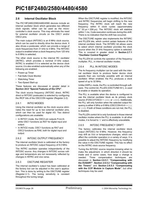
2.6 Internal Oscillator Block<br />
The <strong>PIC18F2480</strong>/<strong>2580</strong>/<strong>4480</strong>/<strong>4580</strong> devices include an<br />
internal oscillator block which generates two different<br />
clock signals; either can be used as the microcontroller’s<br />
clock source. This may eliminate the need<br />
for external oscillator circuits on the OSC1 and/or<br />
OSC2 pins.<br />
The main output (INTOSC) is an 8 MHz clock source,<br />
which can be used to directly drive the device clock. It<br />
also drives a postscaler, which can provide a range of<br />
clock frequencies from 31 kHz to 4 MHz. The INTOSC<br />
output is enabled when a clock frequency from 125 kHz<br />
to 8 MHz is selected.<br />
The other clock source is the internal RC oscillator<br />
(INTRC), which provides a nominal 31 kHz output.<br />
INTRC is enabled if it is selected as the device clock<br />
source; it is also enabled automatically when any of the<br />
following are enabled:<br />
• Power-up Timer<br />
• Fail-Safe Clock Monitor<br />
• Watchdog Timer<br />
• Two-Speed Start-up<br />
These features are discussed in greater detail in<br />
Section 24.0 “Special Features of the CPU”.<br />
The clock source frequency (INTOSC direct, INTRC<br />
direct or INTOSC postscaler) is selected by configuring<br />
the IRCF bits of the OSCCON register (Register 2-2).<br />
2.6.1 INTIO MODES<br />
Using the internal oscillator as the clock source eliminates<br />
the need for up to two external oscillator pins,<br />
which can then be used for digital I/O. Two distinct<br />
configurations are available:<br />
• In INTIO1 mode, the OSC2 pin outputs FOSC/4,<br />
while OSC1 functions as RA7 for digital input and<br />
output.<br />
• In INTIO2 mode, OSC1 functions as RA7 and<br />
OSC2 functions as RA6, both for digital input and<br />
output.<br />
2.6.2 INTOSC OUTPUT FREQUENCY<br />
The internal oscillator block is calibrated at the factory<br />
to produce an INTOSC output frequency of 8.0 MHz.<br />
The INTRC oscillator operates independently of the<br />
INTOSC source. Any changes in INTOSC across voltage<br />
and temperature are not necessarily reflected by<br />
changes in INTRC and vice versa.<br />
2.6.3 OSCTUNE REGISTER<br />
The internal oscillator’s output has been calibrated at<br />
the factory but can be adjusted in the user’s application.<br />
This is done by writing to the OSCTUNE register<br />
(Register 2-1). The tuning sensitivity is constant<br />
throughout the tuning range.<br />
When the OSCTUNE register is modified, the INTOSC<br />
and INTRC frequencies will begin shifting to the new<br />
frequency. The INTRC clock will reach the new<br />
frequency within 8 clock cycles (approximately<br />
8*32µs = 256 µs). The INTOSC clock will stabilize<br />
within 1 ms. Code execution continues during this shift.<br />
There is no indication that the shift has occurred.<br />
The OSCTUNE register also implements the INTSRC<br />
and PLLEN bits, which control certain features of the<br />
internal oscillator block. The INTSRC bit allows users<br />
to select which internal oscillator provides the clock<br />
source when the 31 kHz frequency option is selected.<br />
This is covered in greater detail in Section 2.7.1<br />
“Oscillator Control Register”.<br />
The PLLEN bit controls the operation of the frequency<br />
multiplier, PLL, in internal oscillator modes.<br />
2.6.4 PLL IN INTOSC MODES<br />
The 4x frequency multiplier can be used with the internal<br />
oscillator block to produce faster device clock<br />
speeds than are normally possible with an internal<br />
oscillator. When enabled, the PLL produces a clock<br />
speed of up to 32 MHz.<br />
Unlike HSPLL mode, the PLL is controlled through software.<br />
The control bit, PLLEN (OSCTUNE), is used<br />
to enable or disable its operation.<br />
The PLL is available when the device is configured to<br />
use the internal oscillator block as its primary clock<br />
source (FOSC3:FOSC0 = 1001 or 1000). Additionally,<br />
the PLL will only function when the selected output frequency<br />
is either 4 MHz or 8 MHz (OSCCON = 111<br />
or 110). If both of these conditions are not met, the PLL<br />
is disabled.<br />
The PLLEN control bit is only functional in those internal<br />
oscillator modes where the PLL is available. In all other<br />
modes, it is forced to ‘0’ and is effectively unavailable.<br />
2.6.5 INTOSC FREQUENCY DRIFT<br />
The factory calibrates the internal oscillator block<br />
output (INTOSC) for 8 MHz. However, this frequency<br />
may drift as VDD or temperature changes, which can<br />
affect the controller operation in a variety of ways. It is<br />
possible to adjust the INTOSC frequency by modifying<br />
the value in the OSCTUNE register. This has no effect<br />
on the INTRC clock source frequency.<br />
Tuning the INTOSC source requires knowing when to<br />
make the adjustment, in which direction it should be<br />
made and in some cases, how large a change is<br />
needed. Three compensation techniques are<br />
discussed in Section 2.6.5.1 “Compensating with<br />
the EUSART”, Section 2.6.5.2 “Compensating with<br />
the Timers” and Section 2.6.5.3 “Compensating<br />
with the CCP Module in Capture Mode”, but other<br />
techniques may be used.<br />
DS39637A-page 26 Preliminary © 2004 <strong>Microchip</strong> Technology Inc.