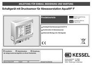
KESSEL-Pumpstation Aqualift€F/Aqualift€F Duo For all wastewaters ...
KESSEL-Pumpstation Aqualift€F/Aqualift€F Duo For all wastewaters ...
KESSEL-Pumpstation Aqualift€F/Aqualift€F Duo For all wastewaters ...
You also want an ePaper? Increase the reach of your titles
YUMPU automatically turns print PDFs into web optimized ePapers that Google loves.
9. Control unit<br />
9.1 Control unit for single pump pumpstation Aqualift F<br />
9.1.1 Description of displays and operational button on control unit<br />
LED Display<br />
Normal operation Betriebʼ light green Main power supply ok<br />
(Information “Alarm“ level yellow “Alarm“-level reached<br />
for User) “On2“ level yellow pump 2 on level reached<br />
“On1“ level yellow pump 1 on level reached<br />
“Off“ level yellow Pump off level reached<br />
Pump1 green pump outlet activated<br />
Warnings Phase / Rotation red constant - phase not active<br />
(Information for Tradesman) blinking - rotating field problem<br />
Motor protection red Motor protection switch has been activated<br />
switch<br />
Motor temperature red Light blinks – ʻTemperature Aʼ (TF)<br />
Light constant – 'Temperature Bʼ (E7)<br />
recorded<br />
Running time/level red Light constant - running time failure<br />
Light blinks - level failure recorded<br />
Buttons<br />
Hand - 0 - Auto Rotating switch Chooses mode of operation<br />
Alarm Reset button Turns off alarm from level switch<br />
Turns off level failure alarm<br />
Turns of motor temperature alarm<br />
Motor protection switch1 switch Activated when pump overloads<br />
• The control buttons can be accessed by removing the<br />
transparent cover of the Aqualift F control unit. The cover<br />
should only be removed and the control buttons accessed<br />
by a licensed professional<br />
• During the time that the transparent control unit cover is removed,<br />
the control unitʼs protection class is reduced. In the<br />
case that a humid condition or splashing water may be present<br />
- first unplug the control unit before removing the transparent<br />
cover.<br />
• The current for the motor protection switch must be set appropriately<br />
according to the requirements of the motor and<br />
must not be set or changed by the operator / owner.<br />
• Be sure that the transparent cover is properly replaced and<br />
secured so that the proper protection class is ensured.<br />
28


