KESSEL-Pumpstation Aqualift€F/Aqualift€F Duo For all wastewaters ...
KESSEL-Pumpstation Aqualift€F/Aqualift€F Duo For all wastewaters ...
KESSEL-Pumpstation Aqualift€F/Aqualift€F Duo For all wastewaters ...

You also want an ePaper? Increase the reach of your titles
YUMPU automatically turns print PDFs into web optimized ePapers that Google loves.
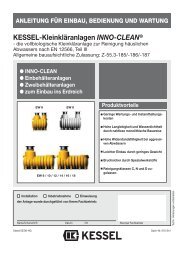
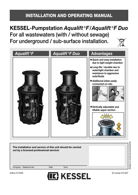
INSTALLATION AND OPERATING MANUAL<br />
<strong>KESSEL</strong>-<strong>Pumpstation</strong> Aqualift F/Aqualift F <strong>Duo</strong><br />
<strong>For</strong> <strong>all</strong> <strong>wastewaters</strong> (with / without sewage)<br />
<strong>For</strong> underground / sub-surface inst<strong>all</strong>ation.<br />
Aqualift F Aqualift F <strong>Duo</strong> Advantages<br />
Quick and easy inst<strong>all</strong>ation<br />
due to light weight chamber<br />
Long-life / durable due to<br />
watertight chamber and<br />
resistance to aggressive<br />
soils/fluids<br />
Additional inlets easily<br />
connected on-site.<br />
Vertic<strong>all</strong>y adjustable and<br />
tiltable upper section<br />
The inst<strong>all</strong>ation and service of this unit should be carried<br />
out by a licensed professional servicer<br />
Company - Telephone No. Date Town<br />
Edition 07/2009<br />
ID number 010-607<br />
(Subject to technical amendment)
This Inst<strong>all</strong>ation Manual contains safety instructions for the inst<strong>all</strong>ation, operation and maintenance of this system. Please<br />
be aware of the following symbols:<br />
Danger symbol for people / personnel according to ISO 3864-B-3-1<br />
Danger symbol for electrical current according to ISO 3864-B-3-6<br />
Safety symbol according to DIN 4844-W8 for marking instructions which need to be followed in order<br />
to maintain the explosion proof rating according to RL 94/9/EG (ATEX 100a)<br />
Caution<br />
This word denotes safety instructions which if not followed could result in damage to the<br />
system or its function<br />
This User´s Manual should always remain with the <strong>Pumpstation</strong> Aqualift F.<br />
Dear Customer,<br />
thank you for choosing a <strong>KESSEL</strong> pumping station.<br />
This entire system has passed a strict quality control inspection before leaving <strong>KESSEL</strong> headquarters. Upon delivery of<br />
the lifting station please thoroughly inspect it to make sure that it has not been damaged during shipping and that the delivery<br />
is complete.<br />
In case damage has occurred to the lifting station or the delivery was not complete, please follow the instructions listed in<br />
the ´Guarantee` section of this user´s manual.<br />
Before the <strong>KESSEL</strong> - Aqualift F <strong>Pumpstation</strong> is inst<strong>all</strong>ed and placed into operation please carefully read and follow <strong>all</strong> of<br />
the instructions contained in this Inst<strong>all</strong>ation, Maintenance and User´s Manual.<br />
<strong>KESSEL</strong> GmbH
Contents<br />
1. Safety precautions .............................................................................................page 4<br />
2. General 2.1 Application / Inst<strong>all</strong>ation.......................................................page 6<br />
2.2 Aqualift F description ...........................................................Page 6<br />
3. Technical Data 3.1 Explosion proof pumps according to ATEX..........................page 7<br />
3.2 Switching levels ...................................................................page 8<br />
3.3 Electrical control unit ...........................................................page 8<br />
4. Inst<strong>all</strong>ation 4.1 Inst<strong>all</strong>ation ...........................................................................page 10<br />
4.2 Pipe connections .................................................................page 13<br />
4.3 Inst<strong>all</strong>ation of the submersible pump(s)...............................page 14<br />
5. Electrical Connections 5.1 General instructions.............................................................page 15<br />
5.2 Mounting the control unit .....................................................page 15<br />
5.3 Information concerning explosion protection .......................page 15<br />
5.4 Inst<strong>all</strong>ation – cable connection ............................................page 15<br />
5.5 Electrical connections..........................................................page 15<br />
5.6 Motor protection switch........................................................page 19<br />
5.7 Pump configuration control..................................................page 19<br />
5.8 Completion of electrical work...............................................page 19<br />
6. Commissioning 6.1 General instructions.............................................................page 20<br />
6.2 Storage / non-operation.......................................................page 20<br />
6.3 Description of operation.......................................................page 21<br />
6.4 Operational test ...................................................................page 22<br />
7. Inspection and Maintenance 7.1 General instructions.............................................................page 22<br />
7.2 Pump ...................................................................................page 23<br />
7.3 Control unit ..........................................................................page 23<br />
7.4 Pump dissassembly.............................................................page 23<br />
8. Problems and Solutions 8.1 General problems ................................................................page 24<br />
8.2 Irregular level conditions......................................................page 25<br />
8.3 Disturbances / Internal controls ...........................................page 26<br />
8.4 Failure warnings ..................................................................page 27<br />
8.5 Alarm warnings....................................................................page 27<br />
8.6 What to do when..................................................................page 27<br />
9. Control Unit 9.1 Control unit for single pump.................................................page 28<br />
9.2 Control unit for double pump ...............................................page 31<br />
10. Replacement parts .............................................................................................page 34<br />
11. Warranty .............................................................................................page 34<br />
3
1. Safety precautions<br />
General Safety Precautions<br />
During inst<strong>all</strong>ation, operation, maintenance and repair of this system it is important to follow <strong>all</strong> appropriate<br />
DIN and VDE safety precautions as well as any application precautions in your area.<br />
Addition<strong>all</strong>y the safety precautions relating to explosion risks in wastewater pumping systems must be followed.<br />
In danger areas, such as pump stations or septic systems, it is important that systems with explosion<br />
proof ratings are inst<strong>all</strong>ed. Inst<strong>all</strong>ation and connection of these units should only be handled by licensed,<br />
professional inst<strong>all</strong>ers<br />
Qualified Personnel<br />
Personnel responsible for the operation, maintenance, inspection and repair of this system must be fully trained<br />
and licensed. It is the responsibility of the owner or operator of this system to insure that the person(s)<br />
responsible for this system are fully trained and licensed. If this is not the case the existing personnel must<br />
be immediately trained or replaced with trained and licensed personnel. It is also the responsibility of the<br />
owner or operator to make sure that the responsible personnel have read through and are completely familiar<br />
with this User´s and Maintenance Manual.<br />
Caution - The Aqualift F uses electricity to operate rotating and mechanical parts.<br />
Not following the User´s Manual can result in damage to the unit as well as injury or a possible fatal accident.<br />
Before maintaining or servicing the Aqualift F make sure to disconnect it from ALL power sources and secure<br />
that power cannot be re-connected during maintenance / servicing. During electrical inst<strong>all</strong>ation or servicing<br />
of the unit, switches VDE 0100 and <strong>all</strong> applicable safety regulations should be followed.<br />
The control units are electric<strong>all</strong>y powered systems which should not be opened or serviced except by licensed<br />
professional electricians. Licensed professional electrician is defined in VDE 0105.<br />
It is important that <strong>all</strong> electrical cables and units relating to the Aqualift F are always in good operating condition.<br />
If damage to any of the electrical cables or systems of the Aqualift F is noticed, the Aqualift F unit must<br />
be immediately disconnected and taken off line.<br />
Danger of hot surfaces<br />
During operation, the Aqualift F may become hot. Take caution before touching or coming into contact with<br />
<strong>all</strong> hot surfaces on the Aqualift F.<br />
Danger for hands and fingers<br />
The Aqualift F pump is equipped with external macerating blades. In order for the system to operate properly<br />
the blades are exposed and unprotected. Any inspection or maintenance work must take place after<br />
the Aqualift F has been fully disconnected from its power source. Also, during maintenance and inspection<br />
take caution of any sharp surfaces or edges.<br />
Slip / Crush / F<strong>all</strong> dangers<br />
Due to risks during entry into the pumping station chamber, it is important that a second party remain outside<br />
of the chamber and oversee the person entering and performing work on the pumping system.<br />
4
1. Safety precautions<br />
Heavy weight - Caution<br />
The pre-assembled base excluding pump(s) of the <strong>KESSEL</strong> Aqualift F weigh between 40 and 60 kg, an<br />
individual pump weighs approximately 39 kg. The cast iron manhole covers weigh between 38 – 58 kg<br />
based on their load class. The Aqualift F units should be handled by at least two people equipped with<br />
appropriate equipment (e.g. safety shoes, back support, winching devices).<br />
Health Safety<br />
The Aqualift F is designed to pump wastewater containing untreated raw sewage which may pose a health<br />
hazard. It is important that no direct or indirect contact between the Aqualift F and skin, eyes or mouth<br />
occurs. If contact does occur it is important to immediately wash and disinfect the contaminated area. In<br />
addition, the atmosphere inside the pumpstation chamber can also pose a health risk. Before entering<br />
the chamber be sure to properly vent the entire chamber. During access an active ventilation system<br />
must also be in place and operating. It is recommended that anyone entering the chamber is equipped<br />
with a portable multi-warning device with audible and optical alarm. This person should be harnessed<br />
to a hoisting device set up above the cover of the chamber – this hoisting device should be operated by<br />
a second individual. Please follow <strong>all</strong> local and international codes regarding this system and always follow<br />
closed access regulations.<br />
Noise<br />
During operation of the Aqualift F pumps emit noise. Based on the inst<strong>all</strong>ation of the Aqualift F this could<br />
present a nuisance. Take care in selecting the inst<strong>all</strong>ation location of the system.<br />
Pump operation<br />
Before placing the pump(s) into operation please observe the conditions on site. The use and operation<br />
of the pumps must be in accordance with explosion proof regulations.<br />
• Dry-running or semi-submersion of the pumps must not occur! The cutting blades, impeller and<br />
pump housing must always be submerged underwater<br />
• The minimal submersion level must always be maintained!<br />
• The pump(s) may not be placed into operation when people are located in the wastewater<br />
storage area of the pumping systems.<br />
• During operation, the pump(s) build up a pressure inside the storage tank<br />
Surrounding conditions / lighting<br />
Any additional equipment brought into the pumping station (such as external lighting or power tools) must<br />
be equipped with the explosion proof rating.<br />
Information concerning the Explosion Proof Rating<br />
The set up of systems in an explosion risk area must follow the 94/9/EG (ATEX 100a).<br />
The pump(s) are to be secured with an overload breaker. This can be accomplished inside the system´s<br />
control unit by doing the following:<br />
Current limitation (motor protection device according to EN 60 974-2). A shut down of the motors during<br />
operation by a 1.15 factor current within 15 minutes.<br />
Temperature control device with a bi-metal switch in stator.<br />
5
2. General<br />
2.1 Application / Inst<strong>all</strong>ation<br />
The Aqualift F <strong>Pumpstation</strong> is designed to automatic<strong>all</strong>y<br />
pump wastewater (with or without sewage collected below<br />
the outgoing sewer level) up to the sewer level so that it may<br />
flow with gravity out of the building and into a septic system<br />
/ public sewer piping. This system is only for use with wastewater<br />
draining from single and multi-family homes, commercial<br />
buildings, hotels, restaurants, hospitals, schools or<br />
similar buildings. In circumstances where the interruption of<br />
wastewater is not <strong>all</strong>owed or desired, a twin pump system<br />
(<strong>Pumpstation</strong> Aqualift F <strong>Duo</strong>) is required for inst<strong>all</strong>ation.<br />
The <strong>KESSEL</strong> <strong>Pumpstation</strong> Aqualift F is designed for outdoor<br />
underground inst<strong>all</strong>ation. Pumps are equipped with macerating<br />
blades which cut <strong>all</strong> soft objects into sm<strong>all</strong>er pumpable<br />
pieces. Due to the cutting blades, outlet pipes of DN 40<br />
or larger may be connected to the outlet of the <strong>Pumpstation</strong><br />
Aqualift F. Objects. The system is designed to handle a continuous<br />
inflow of wastewater up to 40 deg C (104 deg F).<br />
Options for the <strong>KESSEL</strong> <strong>Pumpstation</strong> Aqualift F include:<br />
• Single (1 pump) or Twin (2 pumps)<br />
• Pumps available with various power ratings<br />
• In <strong>KESSEL</strong> 800 or 1000mm diameter Inspection Chamber<br />
• Inst<strong>all</strong>ation depths from 1.5 to 5 meters.<br />
The pump support bases, closure valve, backflow prevention<br />
flap, outlet pressure pipe and float switches have already<br />
been inst<strong>all</strong>ed in the base of the chamber. The pump(s), additional<br />
chamber sections and the electrical control unit are<br />
shipped separately with the system. The pumps, depending<br />
on their size, are shipped either in the chamber upper section<br />
or on a separate p<strong>all</strong>et. The pumps are to be inst<strong>all</strong>ed<br />
only after the complete chamber has been completely assembled<br />
and inst<strong>all</strong>ed. In order to prevent the build up of dangerous<br />
gases in the chamber which can cause an explosion<br />
risk, the system must be ventilated appropriately.<br />
2.2 Aqualift F description<br />
The <strong>KESSEL</strong> <strong>Pumpstation</strong> Aqualift F in single or twin pump<br />
variations is comprised of the following systems.<br />
1. Single or double sewage pumps with cutting assembly<br />
2. <strong>KESSEL</strong> Inspection Chamber 800 or 1000<br />
(mm diameter)<br />
3. Curve pump support base<br />
4. Closure valve for each pump<br />
5. Backflow prevention flap<br />
6. Pressure pipe outlet connection PN 10 from<br />
PEHD DN 50 (Outside Diameter – 63 mm or DN 80<br />
(Outside Diameter – 90 mm)<br />
7. Connection for ventilation pipe (DN 100)<br />
8. Connection for power / control cables (DN 100)<br />
9. Connection for inlet DN 100/150<br />
10. Float switch<br />
11. Electrical control unit (See Chapter 8)<br />
8<br />
7<br />
9<br />
2<br />
4<br />
6<br />
5<br />
1<br />
3<br />
10<br />
Illustration shows <strong>KESSEL</strong> <strong>Pumpstation</strong> Aqualift F<br />
twin pumping unit<br />
6
3. Technical Data<br />
3.1 Explosion proof pumps according to ATEX<br />
Type TPF 1.3 TPF 1.9<br />
Rated input P1 1.75 kW 2.6 kW<br />
Rated output P2 1.3 kW 1.9 kW<br />
Operating voltage 400 V DS 400 V DS<br />
Frequency 50 Hz 50 Hz<br />
Current 3.56 Amps 4.5 Amps<br />
Cables 10 m Length 7 x 1,5 mm 2 10 m Length 7 x 1,5 mm 2<br />
Fuses 3 x 16 Amps 3 x 16 Amps<br />
Protection IP 68 IP 68<br />
Wastewater temp. 40 º C 40 º C<br />
Max running time at 40 deg C 640 minutes (see settings in chapter 5.7)<br />
Pump weight 39 kg 39 kg<br />
0081 II 2G EEx d IIB T4 PTB 03 ATEX 1140<br />
Classifications:<br />
• Operating modes: Pump submerged – Continuous run S1<br />
• Pumps with the TPF . . . ex identification according to Unit Group II, Unit Category 2G (Explosion endangered<br />
areas Zone 1 and 2) are designed for inst<strong>all</strong>ation in atmospheres containing dangerous gases which require the<br />
Explosion Group IIB and the Temperature Class T4. Pumps constructed according to this designation comply with<br />
the ignition protection type „pressure protection encapsuled`.<br />
Power Curve<br />
35<br />
Qmin according to DIN 1986 (vmin = 0,7m/s)<br />
for DN 50 for DN 80<br />
Height [m]<br />
30<br />
25<br />
20<br />
TPF 1,9 kW<br />
15<br />
10<br />
TPF 1,3 kW<br />
5<br />
0<br />
0 5 10 15 20<br />
0 1 2 3 4 5<br />
Flow Q<br />
[m 3 /h]<br />
[l/s]<br />
7
3. Technical data<br />
3.2 Switching levels. Separate power source with blue cables and float switches<br />
Chamber 800 Chamber 1000<br />
Vol (l) difference (approx) Height difference (cm) Vol (l) difference (approx) Height difference (cm)<br />
Single Pump Unit<br />
Off – On 150 31 230 31<br />
On – Alarm 90 20 150 20<br />
Double Pump Unit<br />
Off – On1 - - 200 31<br />
On1 – On2 - - 70 10<br />
On2 – Alarm - - 70 10<br />
The alarm levels are located approximately at the base of the inlet level.<br />
3.3 Electrical control unit with separate power source<br />
according to ATEX.<br />
3.3.1 General technical data<br />
Required Fuse –<br />
max 16 Amp / phase (provided on-site)<br />
3.3.2 Control Unit Protection<br />
IP 56 based on appropriate inst<strong>all</strong>ation and securely closed<br />
see-thru cover<br />
IP 21 – without see-thru cover and standard w<strong>all</strong> inst<strong>all</strong>ation<br />
3.3.3 Appropriate use<br />
Information concerning the appropriate use of<br />
the control unit in areas at risk of explosion.<br />
The control unit is designed to operate <strong>KESSEL</strong> single or<br />
double pump lifting stations with the use of float switches.<br />
The control is to be inst<strong>all</strong>ed outside of the area designated<br />
as at risk of explosion.<br />
Classifications<br />
II (1) G [EEx ia] IIC/IIB<br />
(Group II, Category (1)G, designated<br />
for use in gaseous atmospheres)<br />
The requirements of Norms EN 50014:1997 + A1 – A2, EN<br />
50020:2002 have been fulfilled.<br />
EG – Certification<br />
LCIE 06 ATEX 6043X<br />
Identification<br />
II (1) G [EEx ia] IIC/II B 0081 Ta = 0 ... + 50°C<br />
Inst<strong>all</strong>ation / Commissioning<br />
The lifting stations must be inst<strong>all</strong>ed, connected and commissioned<br />
only by a licensed professional. This professional must be trained<br />
and certified in areas including types of ignition, regulations and<br />
work in areas at risk of explosion. Check to make sure that the<br />
pump classification (listed above) satisfies the requirements of the<br />
inst<strong>all</strong>ation area.<br />
• Temperatures in the immediate area of the pumping station<br />
must remain between<br />
0 – 50 deg Celsius (32 – 122 deg F).<br />
Electrical data / Connections<br />
Power supply – 3 x 400 Volt (AC) / 50 Hz +- 10%<br />
Jacks – N, L1, L2, L3 PE) 230 V (AC) / 50 Hz +- 10% to<br />
supply electronics<br />
Um = 253 V<br />
Based on type – max 11 VA<br />
(Electronic with protection)<br />
up to max 16 VA (Electronic with<br />
protection)<br />
Incoming power<br />
Switch contact U=24V, I=20mA<br />
(jacks TF, TF1, TF2, E7,<br />
E8, E9, E10, based on model) PTC – switch Um = 253 V<br />
Exiting power<br />
(Jacks N, L1)<br />
(Jacks L1, L2, L3)<br />
U = 230 V +- 10%, 2A, 50 Hz<br />
(Warning, Relay) Um = 253 V<br />
U = 400 V +- 10%, less then or<br />
equal to 4KW, 50 Hz<br />
(motor protection switch).<br />
8
3. Technical data<br />
Control unit power circuit passive (Control unit and buttons)<br />
Single pump lifting station<br />
Power level circuit<br />
Jacks OFF, ON, ALARM<br />
in ignition protection characteristics<br />
EEx ia IIC / IIB<br />
Highest values: Uo = 15.8 V<br />
Io = 22 mA<br />
Po = 86 mW<br />
linear curve<br />
Maximum effective interior inductivity and capacities are minimal<br />
EEx ia IIC IIB<br />
highest certifiable 73 mH 290 mH<br />
exterior inductivity<br />
highest certifiable<br />
exterior conductivity<br />
478 nF 2,88 uF<br />
If concentrated capacities / capacities exist in the power level circuit<br />
the following highest certifiable values should be used.<br />
EEx ia IIC IIB<br />
highest certifiable 2 mH 5 mH<br />
exterior inductivity<br />
highest certifiable<br />
exterior conductivity<br />
420 nF 1,8 uF<br />
Double pump lifting station<br />
Power level circuit<br />
Jacks OFF, ON1, ON 2<br />
in ignition protection characteristics<br />
EExja IIC / II<br />
Highest values: Uo = 18,8 V<br />
Io = 29 mA<br />
Po = 115 mW<br />
linear curve<br />
• Maximum effective interior inductiveness and capacities are<br />
minimal.<br />
EEx ia IIC IIB<br />
highest certifiable 42 mH 168 mH<br />
exterior inductivity<br />
highest certifiable<br />
exterior conductivity<br />
478 nF 2,88 uF<br />
If concentrated capacities / capacities exist in the power level circuit<br />
the following highest certifiable values should be used.<br />
Inst<strong>all</strong>ation / Assembly<br />
• All appropriate local and national codes must be followed<br />
• Regulations (including safety regulations) concerning the inst<strong>all</strong>ation<br />
must be followed<br />
• Also consider the inst<strong>all</strong>ation and assembly instruction of<br />
EEx ia IIC IIB<br />
highest certifiable 2 mH 5 mH<br />
exterior inductivity<br />
highest certifiable<br />
exterior conductivity<br />
410 nF 1,8 uF<br />
non- ATEX relevant units<br />
Maintenance<br />
• Removal of the see-thru control unit cover reduces the water /<br />
moisture proof effectiveness of the control unit. In the case that<br />
the control unit is in a very moist, humid or splash endangered<br />
area, make sure to disconnect power to the control unit before<br />
handling or maintenance work is attempted. Removing the<br />
cover of the control unit should only be done by a licensed service<br />
professional.<br />
• After maintenance is completed on the control unit, it is important<br />
that the control unit cover is properly closed and secured.<br />
• No changes should be made to the control unit – such as removal<br />
of the protective see-thru cover. In the case that the control<br />
unit does not function or is damaged, please contact the<br />
manufacturer.<br />
• If required, data sheets, EG – certifications, User´s Manuals and<br />
EG conformity certifications can be requested form the manufacturer.<br />
3.3.4 Control unit outputs<br />
„Warning” relay<br />
Change over contact; opener, middle contact, closer each<br />
with max 2A<br />
„Alarm” relay<br />
Change over contact; opener, middle contact, closer each<br />
with max 2A<br />
Power<br />
2 x N max. 2A each<br />
2 x L1 max. 2A each<br />
Motor (single pump unit)<br />
Motor PE Power connections (grey double inlet jack)<br />
Motor U T1 Protection<br />
Motor V T2 Protection max. 4 kW<br />
Motor W T3 Protection<br />
Motor ½ (double pump unit)<br />
Motor ½ PE Power connection<br />
quadruple power jacks<br />
Motor ½ U T1 protection ½<br />
Motor ½ V T2 protection ½ max. 4 kW<br />
}<br />
Motor ½ W T3 protection ½<br />
}<br />
9
4. Inst<strong>all</strong>ation<br />
The delivered shipment should include the following:<br />
- <strong>KESSEL</strong> Inspection Chamber delivered in sections<br />
(for assembly on-site)<br />
- Sewage pump(s)<br />
- Electrical Control Unit<br />
highest possible groundwater level) must be covered / surrounded<br />
by concrete.<br />
Important:<br />
After receiving the Aqualift F but before inst<strong>all</strong>ation, it is<br />
important that the control unit is stored in a dry, frost free<br />
area until time of connection. The cable ends of the float<br />
switches must not come in contact with water while they<br />
are being stored.<br />
Chamber Inst<strong>all</strong>ation<br />
Paving stones<br />
Inst<strong>all</strong>ation without groundwater<br />
Granite stones<br />
Paving stones<br />
- Caution- Heavy weight<br />
- The base of the inspection chamber as well as the<br />
pumps and chamber cover each way over 30 kg! Be sure<br />
that appropriate personnel and equipment (e.g. safety<br />
shoes, back support, etc.) are used. The pumps should<br />
be placed into the chamber after the chamber is inst<strong>all</strong>ed<br />
and lowered into the chamber only with an appropriate<br />
winch / lowering assembly.<br />
- Caution - Danger of slipping<br />
- While entering or working in or around a chamber the<br />
danger of slipping is always present. Due to this it is<br />
mandatory that a second worker always remains outside<br />
of the chamber to aide / observe the other.<br />
- Caution – Danger of tipping<br />
- Before the trench / hole is backfilled with soil, the possibility<br />
that the chamber tips or f<strong>all</strong>s is always present. Due<br />
to this, entry into the chamber should only take place<br />
after the hole, in which the chamber is inst<strong>all</strong>ed, is backfilled<br />
4.1 Inst<strong>all</strong>ation<br />
The base / bottom of the hole in which the Aqualift F is to be<br />
inst<strong>all</strong>ed should be prepared with 30 cm even layer of compacted<br />
gravel. On top of this layer of gravel should be a 10<br />
cm thick evenly compacted layer of fine gravel. Now place<br />
the bottom section of the pumping chamber into the excavation<br />
making sure that inlets / outlet, ventilation and pipe cable<br />
outlets are in the correct location.<br />
The excavation is then to be backfilled in 30 cm layers with<br />
gravel (gravel to be group G1 according to ATV-A127). Each<br />
of these 30 cm layers is to be compacted with a light duty<br />
compactor. Make sure to connect any necessary inlets / outlet<br />
or other pipes before these areas are backfilled. In the<br />
case that the chamber is to be inst<strong>all</strong>ed in an area that is subject<br />
to rising groundwater, the chamber must be protected<br />
against floatation. To protect the chamber against groundwater<br />
the entire lower portion of the chamber (including the<br />
bottom of the chamber)(up to a height that is higher than the<br />
gravel<br />
30 cm gravel<br />
Earth<br />
Earth<br />
Earth<br />
gravel<br />
30 cm gravel<br />
The inst<strong>all</strong>ation of the chamber needs to take into<br />
consideration the appropriate load class. Inst<strong>all</strong>ations in<br />
standard traffic areas (Load Class B - 12.5 metric tons)<br />
require that the upper section is firmly compacted into the<br />
surrounding backfill.<br />
<strong>For</strong> inst<strong>all</strong>ation in areas with high groundwater, the chamber<br />
needs to be secured against floatation. In addition to<br />
this a re-enforced, groundwater resistant chamber base is<br />
available at additional cost.<br />
10
4. Inst<strong>all</strong>ation<br />
Inst<strong>all</strong>ing the chamber seals / gaskets<br />
Inst<strong>all</strong>ing chamber sections<br />
Each of chamber sections is connect using a gasket (the size<br />
of this gasket will vary depending on if an 800 or 1000 chamber<br />
is being inst<strong>all</strong>ed and on the specific section being inst<strong>all</strong>ed.<br />
The recessed area for the gasket (located on the top<br />
of each section as seen in the illustration) should be clean<br />
and free from <strong>all</strong> debris / sand. Firmly place the gasket into<br />
the recessed area of the chamber. After the entire gasket has<br />
been inst<strong>all</strong>ed – grease the exposed upper portion of the<br />
gasket with a standard gasket lubricant.<br />
Access step inst<strong>all</strong>ation<br />
Now place the next chamber section on top of the other making<br />
sure that the location for access steps are in line with the<br />
lower portion. The steps should be in a left / right / left / right<br />
pattern to aide in accessing the chamber after inst<strong>all</strong>ation is<br />
complete. If connected properly the 600mm open access to<br />
the chamber in the cone section should be directly above the<br />
pump(s) and the pump guide rail(s) which will provide proper<br />
access to the pumps for removal and inst<strong>all</strong>ation.<br />
The sections are secured with another with the supplied<br />
connection clips which should be inst<strong>all</strong>ed as illustrated<br />
below.<br />
Inst<strong>all</strong>ing the vertic<strong>all</strong>y adjustable upper sections<br />
• Firmly insert<br />
custom gasket<br />
into recessed<br />
area<br />
of cone section<br />
using<br />
hammer if required<br />
• Grease<br />
custom gasket,<br />
insert<br />
upper section<br />
and secure<br />
with<br />
clamping<br />
ring.<br />
Access steps (included with <strong>KESSEL</strong> 1000 chamber) (Available<br />
as accessory with <strong>KESSEL</strong> 800 chamber). Access<br />
steps may be inst<strong>all</strong>ed prior to assembling the individual<br />
chamber sections. Steps are inst<strong>all</strong>ed as shown in the diagram<br />
below.<br />
• Final elevation<br />
/ slope<br />
adjustments<br />
can be made<br />
with the 3<br />
adjustment<br />
screws.<br />
11
4. Inst<strong>all</strong>ation<br />
After the upper section has been set to its final elevation and<br />
slope, it is important to note the following:<br />
• Cobble stone inst<strong>all</strong>ation<br />
• in the case that the upper section and cover will be inst<strong>all</strong>ed<br />
in a stone / cobble stone surface, it is important that the<br />
top of the upper section is inst<strong>all</strong>ed approx 2 cm higher than<br />
that of the cobble stones. When the cobble stones are compacted<br />
the upper section (with inst<strong>all</strong>ed cover) should also<br />
be compacted (be sure to tighten cover screws before compacting)<br />
until it is level with the surrounding stones<br />
• Inst<strong>all</strong>ation in automobile traffic areas<br />
• in the case that the upper section and cover will be inst<strong>all</strong>ed<br />
in a surface which is to handle Class D (40.0 metric ton<br />
load classes), a 18cm thick, 2m x 2m B25 concrete support<br />
plate must be poured around the upper section. The concrete<br />
support plate should be steel re-enforced and comply<br />
with any local regulations. A drawing of this load support<br />
plate is available from <strong>KESSEL</strong> upon request.<br />
•„In some instances it may be required that the lower section<br />
of the upper section be sawed off in order to obtain the correct<br />
inst<strong>all</strong>ation depth. This cut should be made as evenly<br />
as possible and any remaining loose edges should be filed<br />
away. The included manhole cover removal key as well as<br />
the User´s Manual for the pumping system should be stored<br />
in a protected dry area in the near vacinity of the control<br />
unit.<br />
Inst<strong>all</strong>ation depths<br />
<strong>KESSEL</strong> – <strong>Pumpstation</strong> Aqualift F in 1000 Inspection Chamber<br />
Inst<strong>all</strong>ation depths from 1.63 to 5.13 meters<br />
<strong>KESSEL</strong> – <strong>Pumpstation</strong> Aqualift F in 800 Inspection Chamber<br />
Inst<strong>all</strong>ation depths from 1.46 to 1.96 meters<br />
12
4.2 Pipe connections<br />
All pipes are to be laid with negative slope into the <strong>Pumpstation</strong><br />
Aqualift F Chamber – meaning that fluids will flow with<br />
gravity out of the pipe and into the pumpstation. All pipe<br />
connections must be flexible connections and be inst<strong>all</strong>ed<br />
with sound dampening accessories. The DN 100/150 pipe<br />
connections for the inlets, ventilation and cable supply can<br />
be made with standard DN 100 or DN 150 KG piping.<br />
Main inlet<br />
(DN 150 connection)<br />
Control unit<br />
Pressure outlet (OD 63 or 90 mm)<br />
according to DIN 1986 should be<br />
inst<strong>all</strong>ed over the backwater level!<br />
According to DIN 1986 the inlet pipe(s) must have a minimum<br />
2 % slope into the pumpstation. Bends and fittings<br />
should be used as little as possible. The connection to the<br />
DN 150 inlet to the pumpstation can be made with a femalefemale<br />
fitting or a DN 100 inlet pipe with reduction.<br />
All electrical cable going to or from the pumpstation should<br />
be inst<strong>all</strong>ed in one DN 100 cable supply pipe. This cable supply<br />
pipe may be used for no other purpose other then running<br />
cables. Curves / Bends in the cable supply pipe should<br />
be handled with 30 or 45 degree fittings (no 67 or 90 degree<br />
bends should be used which could complicate running cables<br />
at a later date). After <strong>all</strong> electrical inst<strong>all</strong>ations have been<br />
completed it is important that the cable supply pipe is completely<br />
protected against air or waste penetration. This can<br />
be accomplished with special cable sealing inserts or with<br />
special expansion foams which will prevent odour transfer<br />
into the building as well as water / moisture entering the basement.<br />
The ventilation pipe serves to compensate negative or positive<br />
pressure build-ups which can occur inside the pumpstation<br />
as it is filled with wastewater or as wastewater is<br />
4. Inst<strong>all</strong>ation<br />
Cable supply pipe<br />
(DN 100 connection)<br />
pumped out of the system. Since these systems are norm<strong>all</strong>y<br />
inst<strong>all</strong>ed close to the building which they serve, it is recommended<br />
that the pumpstation´s ventilation pipe be run to the<br />
roof of the building – this will prevent odour nuisances in the<br />
future. If the opportunity exists, the pumpstation´s ventilation<br />
pipe can be connected to the building´s existing ventilation<br />
pipe.<br />
The pumpstation is shipped with gaskets for securing any<br />
connecting pipes such as the ventilation<br />
pipe and the cable access pipe. These<br />
gaskets should be lubricated before KG<br />
inlet and ventilation piping is attached.<br />
Ventilation pipe<br />
(DN 100 connection)<br />
The outlet pressure pipe (DN 50 /<br />
80)(connected to a private or public<br />
sewer system) should be connected to<br />
the supplied outlet using PN 10 PEHD<br />
DN 50 (OD 63mm) or DN 80 (OD 90mm)<br />
piping. In the case that the DN 80 pressure<br />
outlet is to be used, the DN 50 pressure<br />
pipe reduction should be cut off onsite.<br />
This connection can be made by<br />
butt welding the PE pressure pipes together<br />
or by using appropriate heavy<br />
duty couplings. According to DIN EN<br />
12056, it is important that this outlet pipe<br />
be plumbed over the local backwater<br />
height and then down into the private or<br />
public sewer (this outlet piping must be<br />
protected against freezing). A direct<br />
solid connection from the pressure pipe outlet to the building<br />
should not exist – this will prevent noise /vibrations being<br />
transferred to the building. After the pressure pipe outlet<br />
connections have been completed, it should be pressure tested<br />
to assure that the piping is securely fastened and is<br />
100% watertight.<br />
13
4. Inst<strong>all</strong>ation<br />
4.3 Inst<strong>all</strong>ation of the submersible sewage pump(s).<br />
Caution:<br />
Caution – the Aqualift F submersible TPF 1.3 kW and 1.9<br />
kW pumps weigh 39 kg. These pumps should only be lifted<br />
and inst<strong>all</strong>ed in the pumpstation using appropriate lifting<br />
and pulley devices. If an inst<strong>all</strong>ation or maintenance<br />
worker needs to enter the pumpstation this worker should<br />
be equipped with the appropriate safety devices and there<br />
should always be at least one observer who remains outside<br />
of the chamber<br />
Before inst<strong>all</strong>ing the submersible pumps(s) check the inside<br />
of the pumpstation to make sure it is free of any debris or<br />
waste. Once the chamber is cleaned, the pump(s) should be<br />
lowered with the aide of a mechanical lowering device (pulley)<br />
onto the steel guide rail bars and to the bottom of the<br />
chamber making sure that the pump(s) make firm contact<br />
with the base of the guides. Remove the lowering chain from<br />
the pulley and attach it to the hook located in the upper section<br />
of the chamber so the chain is accessible without entering<br />
the chamber the next time pump service work needs to<br />
be done.<br />
Important:<br />
After inst<strong>all</strong>ing the pump(s) make sure that the closure valves<br />
are in the open position (lever should be in the vertical<br />
position).<br />
4.4 Setting the float switches<br />
The float switches are set in their appropriate positions at the<br />
factory (see illustration 3.2). It is recommended that the position<br />
of these float switches is not changed as it may negatively<br />
effect the operation of the pumps.<br />
Single pump unit<br />
This pumping station is equipped with one submersible sewage<br />
pump. The system is controlled by 3 float switches. The<br />
function of these 3 float switches are Pump OFF, Pump ON<br />
and ALARM. The float switches have been inst<strong>all</strong>ed and set<br />
at the factory. The float switches have been set so that the<br />
ALARM float switch will activate when the wastewater level<br />
inside the chamber reaches the bottom of the inlet pipe level<br />
of the pumpstation<br />
If other pumping levels are desired, the float switches must<br />
be changed on-site. Important is that the ALARM float switch<br />
activation point is not set above the inlet pipe elevation and<br />
that the Pump OFF float switch is not set too low – this will<br />
prevent the pump from intaking air. Ide<strong>all</strong>y, the submersible<br />
pump should be tot<strong>all</strong>y underwater before pumping begins..<br />
Double pump unit<br />
This pumping station is equipped with two identical submersible<br />
sewage pumps. The system is controlled by 4 float switches.<br />
The function of the 4 float switches are Pump OFF,<br />
Pump 1 ON, Pump 2 ON and ALARM. The float switches<br />
have been inst<strong>all</strong>ed and set at the factory. The float switches<br />
have been set so that the ALARM float switch will activate<br />
when the wastewater level inside the chamber reaches the<br />
bottom of the inlet pipe level of the pumpstation.<br />
If other pumping levels are desired, the float switches must be<br />
changed on-site. Important is that the ALARM float switch activation<br />
point is not set above the inlet pipe elevation and that<br />
the Pump OFF float switch is not set too low – this will prevent<br />
the pump(s) from intaking air. Ide<strong>all</strong>y, the submersible pumps<br />
should be tot<strong>all</strong>y underwater before pumping begins<br />
off<br />
Level 1<br />
off<br />
Level 1<br />
Level 2<br />
1) minimum wastewater level<br />
Pump turns off at this wastewater level during automatic operation.<br />
14
5. Electrical connections<br />
NOTICE – Only certified licensed professionals should<br />
conduct the following electrical connections.<br />
5.1 General instructions<br />
The control unit for the <strong>Pumpstation</strong> Aqualift F must be<br />
connected to a separate main switch so that if required the<br />
entire system can be switched off line. This main switch<br />
should be clearly visible and located in the immediate vicinity<br />
of the control unit.<br />
All cables entering the control unit must be secured to the<br />
control unit using the supplied plastic strain relief nuts. Cable<br />
inlet openings into the control unit which are not used must<br />
be properly closed.<br />
Important:<br />
All electrical cables must be properly secured (with tiewraps<br />
for example) so that in the case that the cable<br />
releases from the control unit that the bare ends of the<br />
cables do not come in contact with any other cables (for<br />
example in the case that cable L1 comes out of the input<br />
jacks it will physic<strong>all</strong>y be impossible for this cable to<br />
contact the PELV).<br />
All local and national safety regulation should be followed. If<br />
these codes are not strictly followed, a danger to people and<br />
maintenance workers could exist. After any work on the control<br />
unit has been completed, the see-thru cover must be properly<br />
secured in order that the control unit remains splash<br />
proof.<br />
Float switch cables should be run separately from the pump<br />
power cables.<br />
5.2 Mounting of control unit<br />
The control unit for this pumping station is to be inst<strong>all</strong>ed in<br />
a frost-free, dry and well-ventilated area. The control unit<br />
may not be inst<strong>all</strong>ed in an explosion endangered area. The<br />
control unit is to be inst<strong>all</strong>ed vertic<strong>all</strong>y on a solid w<strong>all</strong> with the<br />
supplied 4 screws – a template is provided to aid in drilling<br />
holes in the w<strong>all</strong>. To access the control unit mounting screws<br />
first remove the see-thru cover. The cables for the pump(s)<br />
and the float switches should be run through an empty pipe<br />
to the control unit. To connect these cables please follow the<br />
instructions in Chapter 5.4 “Inst<strong>all</strong>ation – Cable connection”.<br />
and power and pump cables must be connected to their appropriate<br />
jacks. Improper connection of cables could damage<br />
the system as well as nullify the explosion proof rating of<br />
the system. No external power may be supplied to the float<br />
switch Off, On, On1/On2 or alarm connection jacks.<br />
5.4 Inst<strong>all</strong>ation – Cable connection<br />
The cables for the pump(s) and the float switches are 10 meters<br />
in length. The cables between pumping station and building<br />
must be run in a dedicated empty pipe (as discussed in<br />
Chapter 4.2). In the case that the 10 meter cable lengths are<br />
not sufficient, the cables may be extending following VDE<br />
codes.<br />
Important:<br />
All electrical cables must be inst<strong>all</strong>ed so that they do not<br />
come in contact with the submersible pump(s) and are<br />
clear of the access steps as well as not hindering access<br />
to the chamber. The cable lengths must also assure that<br />
the removal of one or both of the submersible pumps for<br />
inspection and / or maintenance purposes is possible.<br />
5.5 Electrical connections<br />
All electrical connections should be handled by a licensed<br />
professional only and should follow <strong>all</strong> local and international<br />
codes and regulations. The power supplied to the<br />
control unit must match that listed on the control unit.<br />
Cable description<br />
Control unit Standard Variations TF<br />
connection H07RN8-F H07RN8-F S07RC4N8-F<br />
7G 1.52 8G 1.52 8G 1.52 8G 1.52<br />
PE (Protection) green/yellow green/yellow green/yellow green/yellow<br />
U (phase) 1 1 1 black<br />
V (phase) 2 2 2 black<br />
W (phase) 3 3 3 black<br />
20 (TF) 4 4 4 black<br />
21 (TF) 5 5 5 orange<br />
22 (E) 6 6 6 blue<br />
9 -- 7 7 black<br />
5.3 Information concerning explosion protection<br />
When connected cables inside the control unit make sure<br />
that the cables are connected to their appropriate jacks.<br />
Float switch cables must be connected to float switch jacks<br />
15
5. Electrical connections<br />
5.5.1 <strong>Pumpstation</strong> Monitoring Systems<br />
Temperature monitoring<br />
Function description of the thermal monitoring<br />
for Ex protected pumps<br />
The pump temperature is monitored by twin independent<br />
thermal monitors. The first monitoring system (Bimetal temperature<br />
monitor – cables 20 and 21) will shut down the<br />
pump when a certain temperature has been reached. This<br />
monitor will also restart the pump after the pump has cooled.<br />
In the case that the first monitoring system malfunctions, a<br />
second monitoring system (Bimetal temperature alarm – cables<br />
21 and 22) will shut down the pump before it exceeds<br />
that maximum <strong>all</strong>owable explosion proof rated temperature.<br />
The pumps will not restart after they cool down if the second<br />
monitor shuts down the system. In this case the pumpstation<br />
must be inspected.<br />
The explosion proof protection for the pumpstation is only<br />
functionable when the integrated temperature monitor and<br />
temperature alarm are properly connected to the control unit<br />
– as described later in the manual.<br />
5.5.2 Securing of electrical connection cables<br />
The pump power cables must be taught and firmly connected<br />
in the chamber to prevent these cables from being<br />
sucked into the pumps<br />
5.5.5 Pump Rotation Check<br />
Never place hands or any objects near the impeller<br />
of the pump<br />
The control unit includes a pump rotation monitor. In the<br />
case that the phases are improperly connected, an alarm will<br />
sound. Properly connecting power cables as described in<br />
Section 5.5 will guarantee proper pump rotation.<br />
5.5.6 Potential equ<strong>all</strong>ing connection<br />
EN 60 204 regulations regulate potential equ<strong>all</strong>ing. Pumps<br />
with an explosion proof rating are equipped with an internal<br />
threaded M8x20 bolt.<br />
Special requirement for chemic<strong>all</strong>y corrosive fluids:<br />
If the pump unit is used in chemic<strong>all</strong>y corrosive fluids<br />
and is the subject to explosion protection requirements,<br />
the terminal provided on the outside of the<br />
pump unit must not be used.<br />
Instead, the PE conductor sh<strong>all</strong> be connected to a<br />
flange of the discharge pipe which ist not in contact with<br />
the fluid handled. Make sure that electrical contact is<br />
established between the newly created potential equalization<br />
connection and the pump.<br />
5.5.3 Overload Protection System<br />
The motor(s) are protected from overloading by a thermal delayed<br />
overload protection according to VDE 0660. This is set<br />
to the motor´s current – this is displayed on the control unit´s<br />
shield.<br />
5.5.4 Float Switches<br />
The automatic operation of the pumps is controlled by the included<br />
float switches. The lowest pump off level is set to a<br />
level above the minimal level – see section 4.4.<br />
16
5. Electrical connections<br />
On-site electrical connection work is described in the table below as well as on the control unit connection plan (see page<br />
3.1). Please take note of instructions listed in Chapter 9 – Electrical Control Unit.<br />
Connection<br />
Power connection<br />
Motor / pump cables<br />
Single Pump Systems – Follow <strong>all</strong> safety regulations!<br />
Instructions<br />
• Power cables L1, L2, L3, N and PE should be connected to their appropriate jacks (grey<br />
color jacks located on above level). Please see the coded inst<strong>all</strong>ation help located near<br />
the connection area<br />
• It is mandatory that cables N and PE are connected and connected properly.<br />
• The power supply cable to the control unit must be equipped with a main On / Off switch<br />
• Each phase of the main power cable must be equipped with a fuse with a max rating of 16 Amps<br />
• Improper electrical inst<strong>all</strong>ation / connection of the control unit and / or pumps<br />
can damage or destroy the control system<br />
• The motor / pump cables U/V/W should be connected to the ABB-Schütze B6-30-10 jacks T1<br />
/ T2 / T3 which are to the left of the motor protection switches. The direction of rotation of the<br />
motors is to be noted<br />
• The PE cable is to be connected to the lower level of grey jacks according to the coded<br />
inst<strong>all</strong>ation help located near the connection area. Sufficient slack should be left in the<br />
motor cables so that removal of the pump(s) for repair or maintenance is possible.<br />
Motor temperature sensors • Entry TF: Cable 5 from the pump should be connected on the right in entry TF. Cable 4<br />
should be connected to the left of entry TF.<br />
• Entry E7: Cable 6 from the pump should be connected on the left in entry E7.<br />
(remove the bridge if necessary).<br />
Float switch connections -<br />
“Off”, “On” and “Alarm”<br />
• The cable ends of the float switches are to be connected to their corresponding<br />
• marked jacks.<br />
• The connection jacks of the float switches should have no other cables entering them.<br />
• The connection jacks are marked with switching symbols.<br />
Warning and Alarm outputs<br />
• The ʻStörungʼ (malfunction) and ʻAlarmʼ (warning / alarm) control unit signals are controlled<br />
by a relay without a protective safety switch. Inductive loads must be extern<strong>all</strong>y<br />
eliminated. The stand by (powerless) position of the relays is printed on the board.<br />
• The relay contacts have no connection to any power supply or operating voltage of the<br />
system and are safely separated up to an operating voltage of 300 V according to Table<br />
D.10 of the EN 61010 Norm (Overload category 2 u. Contamination level 2).<br />
• The relays are designed to switch 250 V / 2 A. Appropriate external measures should be<br />
taken to limit the current to this level.<br />
• It is not <strong>all</strong>owable to switch phases with the relays. The phase may deviate from L1.<br />
OUTPUTS L1 / N<br />
• The L1 and N outputs (2 each) are designed for an external (extra) warning for the “Mal-<br />
(230V / 50 Hz) • function” and “Alarm” functions. These outputs may not be used for any other purposes.<br />
• Maximum current is 2 amps.<br />
Rechargeable battery<br />
• A NiCd-9V-Block rechargeable battery (Type IEC 6F22) may be inst<strong>all</strong>ed inside the control<br />
unit (it is not included with the control unit). The purpose of this battery is to power the<br />
alarm and notification devices on the control unit during power outages / failures. Do not<br />
use a standard battery! Only use rechargeable batteries that conform to the above specifications<br />
• Only remove or replace the rechargeable battery in the control unit when the<br />
power to the entire control unit has been turned off / disconnected. Make sure<br />
battery polarity is correct<br />
• In the case that a “dead” or power-less rechargeable battery is placed in the control unit,<br />
the unit will require approximately 36 hours to completely re-charge the battery. After 36<br />
hours the battery and the control unit will be fully operational<br />
17
5. Electrical connections<br />
Connection<br />
Power connection<br />
Motor / pump cables<br />
Twin Pump Systems – Follow <strong>all</strong> safety regulations!<br />
Instructions<br />
• Power cables L1, L2, L3, N and PE should be connected to their appropriate jacks (located<br />
on the second level from the bottom). Please see the coded inst<strong>all</strong>ation help located near<br />
the connection area<br />
• It is mandatory that cables N and PE are connected and connected properly<br />
• The power supply cable to the control unit must be equipped with a main On / Off switch<br />
• Each phase of the main power cable must be equipped with a fuse with a max rating of 25 Amps.<br />
• Improper electrical inst<strong>all</strong>ation / connection of the control unit and / or pumps can<br />
damage or destroy the control system.<br />
• The motor / pump cables 2 x U/V/W should be connected to the ABB-Schütze B6-30-10<br />
jacks T1 / T2 / T3 which are below the motor protection switches (pump 1 left / pump 2<br />
right). The direction of rotation of the motors is to be noted.<br />
• The PE cable is to be connected to the lower level of grey jacks according to the coded<br />
inst<strong>all</strong>ation help located near the connection area.<br />
• Sufficient slack should be left in the motor cables so that removal of the pump(s) for<br />
repair or maintenance is possible.<br />
Motor temperature sensors • Entry TF1: Cable 5 from the pump 1 should be connected on the right in entry TF1.<br />
Cable 4 should be connected to the left in entry TF1<br />
• Entry TF2: Cable 5 from the pump 2 should be connected on the right in entry TF2.<br />
Cable 4 should be connected to the left in entry TF2<br />
• Entry E7: Cable 6 from pump 1 should be connected on the left in entry E7. (remove<br />
the bridge if necessary).<br />
• Entry E8: Cable 6 from pump 2 should be connected on the left in entry E8. (remove<br />
the bridge if necessary).<br />
Float switch connections<br />
“Off”, “On”, “On2”<br />
and “Alarm”<br />
Warning and Alarm outputs<br />
• The cable ends of the float switches are to be connected to their corresponding<br />
• marked jacks.<br />
• The connection jacks of the float switches should have no other cables entering them<br />
• The connection jacks are marked with switching symbols<br />
• The ʻStörungʼ (malfunction) and ʻAlarmʼ (warning / alarm) control unit signals are controlled<br />
by a relay without a protective safety switch. Inductive loads must be extern<strong>all</strong>y<br />
eliminated. The stand by (powerless) position of the relays is printed on the board.<br />
• The relay contacts have no connection to any power supply or operating voltage of the<br />
system and are safely separated up to an operating voltage of 300 V according to Table<br />
D.10 of the EN 61010 Norm (Overload category 2 u. Contamination level 2).<br />
• The relays are designed to switch 250 V / 2 A. Appropriate external measures should be<br />
taken to limit the current to this level.<br />
• It is not <strong>all</strong>owable to switch phases with the relays. The phase may deviate from L1.<br />
Outputs L1 / N<br />
• The L1 and N outputs (2 each) are designed for an external (extra) warning for the “Malfunc-<br />
(230V / 50 Hz) •tion” and „Alarm” functions. These outputs may not be used for any other purposes.<br />
• Maximum current is 2 amps<br />
Rechargeable battery<br />
• A NiCd-9V-Block rechargeable battery (Type IEC 6F22) may be inst<strong>all</strong>ed inside the control<br />
unit (it is not included with the control unit). The purpose of this battery is to power the alarm<br />
and notification devices on the control unit during power outages / failures. Do not use a standard<br />
battery! Only use rechargeable batteries that conform to the above specifications.<br />
• Only remove or replace the rechargeable battery in the control unit when the power to the<br />
entire control unit has been turned off / disconnected. Make sure battery polarity is correct<br />
• In the case that a „dead„ or power-less rechargeable battery is placed in the control unit,<br />
the unit will require approximately 36 hours to completely re-charge the battery. After 36<br />
hours the battery and the control unit will be fully operational.<br />
18
5. Electrical connections<br />
5.6 Motor protection switch<br />
The motor protection switch must be set to handle the<br />
appropriate power rating listed in Chapter 3.1 of this User´s<br />
Manual.<br />
The configuration can be set by adjusting the S604 switch<br />
(4-way DIP switch each with ON/OFF setting).<br />
Different settings are not permitted.<br />
5.7 Pump configuration control<br />
The control of the pump configuration is set at the factory<br />
using switches S601 . . . S604 located between the jacks for<br />
the float switches and the motor thermal protection entry<br />
ports. The configurations should be checked to make sure<br />
they are properly set.<br />
S604 / 1<br />
S604 / 2<br />
S604 / 3<br />
S604 / 4<br />
ON<br />
Pump run time controlled<br />
(wastewater lifting station)<br />
Submerisble pump without<br />
Off float switch<br />
Pump rotation monitor<br />
On<br />
Anti blocking function<br />
On<br />
OFF<br />
Level controlled<br />
Submersible pump station<br />
Submersible pump<br />
with Off float switch<br />
Submersible pump<br />
Off<br />
Anti blocking function<br />
Off<br />
- The pump start delay time can be custom set by adjusting the S601 switch. This delay can be set between 0 and 3 seconds<br />
in 0.2 second increments. (tolerance +- 0.1 seconds)<br />
S601<br />
tV [s]<br />
0<br />
0,0<br />
1<br />
0,2<br />
2<br />
0,4<br />
3<br />
0,6<br />
4<br />
0,8<br />
5<br />
1,0<br />
6<br />
1,2<br />
7<br />
1,4<br />
8<br />
1,6<br />
9<br />
1,8<br />
A<br />
2,0<br />
B<br />
2,2<br />
C<br />
2,4<br />
D<br />
2,6<br />
E<br />
2,8<br />
F<br />
3,0<br />
- The maximum running time can be custom set by adjusting the S602 switch. This can be set between 40 and 640 minutes<br />
in 40 minute increments (tolerance +- 4 minutes)<br />
S602<br />
tGL [min]<br />
0<br />
40<br />
1<br />
80<br />
2<br />
120<br />
3<br />
160<br />
4<br />
200<br />
5<br />
240<br />
6<br />
280<br />
7<br />
320<br />
8<br />
360<br />
9<br />
400<br />
A<br />
440<br />
B<br />
480<br />
C<br />
520<br />
D<br />
560<br />
E<br />
600<br />
F<br />
640<br />
- The pump stop delay time can be custom set by adjusting the S603 switch. This can be set between 0.5 and 8 seconds in<br />
0.5 second increments (tolerance +- 0.1 seconds)<br />
S603<br />
tN [s]<br />
0<br />
0,5<br />
1<br />
1,0<br />
2<br />
1,5<br />
3<br />
2,0<br />
4<br />
2,5<br />
5<br />
3,0<br />
6<br />
3,5<br />
7<br />
4,0<br />
8<br />
4,5<br />
9<br />
5,0<br />
A<br />
5,5<br />
B<br />
6,0<br />
C<br />
6,5<br />
D<br />
7,0<br />
E<br />
7,5<br />
F<br />
8,0<br />
Before making any of the above adjustments make sure to<br />
disconnect the Aqualift F from its power source. Any setting<br />
changes should be handled by a licensed professional and<br />
should be documented in this User´s Manual.<br />
Make sure that the pump control switches (Hand – 0 –<br />
Auto) are switched to the “Auto” setting so that the pumpstation<br />
can work in automatic mode.<br />
5.8 Completion of electrical work<br />
After <strong>all</strong> electrical work has been completed on the Aqualift<br />
F or the control unit make sure to replace the cover and the<br />
transparent cover of the control unit. After <strong>all</strong> cables have<br />
been laid in the cable pipe duct, this pipe should be sealed<br />
with a cable sealing flange or with expanding insulation foam<br />
to prevent any odours or moisture from entering the building<br />
where the control unit is stored.<br />
19
6. Commissioning<br />
6.1 General instructions<br />
Please follow DIN 1986 Part 31 when commissioning pumps<br />
/ lifting stations.<br />
Caution - Before commissioning the Aqualift F make sure<br />
that <strong>all</strong> inlet pipes as well Aqualift F storage chamber and the<br />
pump is free from metal, sand or any other potenti<strong>all</strong>y damaging<br />
debris.<br />
Only place the Aqualift F into operation after it has been<br />
thoroughly checked to assure that inst<strong>all</strong>ation and pipe and<br />
electrical connection have been properly made. Make sure<br />
that <strong>all</strong> closure valves are fully open before starting<br />
Important:<br />
the commissioning of the Aqualift F must be handled by a<br />
licensed professional<br />
Make sure to follow <strong>all</strong> safety instructions in Part 1 of this<br />
User´s manual and do not place the Aqualift F in operation if<br />
the pump, control unit or cables show any signs of damage.<br />
Please make sure that the power requirements of the pumpstation<br />
match those of the power supply from the local power<br />
grid. Before placing the system in operation, re-check <strong>all</strong><br />
electrical connections. Also, make sure that <strong>all</strong> local and international<br />
regulations have been followed – especi<strong>all</strong>y those<br />
pertaining to explosion proof wastewater pumping stations.<br />
Do not use this pumping station to pump mediums for which<br />
the pumps or the pumping chamber are not intended.<br />
.<br />
Pre-check:<br />
• Operation data<br />
• Pump oil level<br />
• Impeller rotation direction<br />
• All electrical connections<br />
• Proper inst<strong>all</strong>ation of pump(s) on support feet<br />
The pump(s) must be completely filled with pumping medium<br />
(wastewater) to insure that an explosion risk atmosphere<br />
is prevented. The pump(s) can only be placed into<br />
operation when there is no chance of air entering the intake<br />
portion of the pump.<br />
Commissioning<br />
Before placing the pump(s) into operation, it must be<br />
confirmed that the wastewater level never f<strong>all</strong>s below<br />
the „Minimal Level” (see Chapter 4.4.)<br />
During continuous operation of the pumps (S1), the pumps<br />
must remain completely submerged.<br />
Operating the pumps in non submerged conditions<br />
results in an increase wear and tear on the pumps.<br />
6.1.1 Intake of floating matter<br />
Pumps with S-impellers are recommended for pumping <strong>wastewaters</strong><br />
with floating matter. In these cases, it is recommended<br />
that the pumps run in a slightly tilted position. In addition,<br />
S-impellered pumps should run for an additional 10<br />
seconds after the intake level has been reached.<br />
6.1.2 Pumping medium temperature<br />
Max pumping medium temperature of explosion rated pumps<br />
– 40 deg C.<br />
The operator of this pumpstation must insure that the<br />
operational temperature of this system (pumping medium<br />
temperature) does not exceed this level.<br />
Do not operate this system with pumping mediums<br />
above the noted maximum temperature<br />
6.1.3 Pump Starts<br />
The maximum pump starts per hour must not exceed 30.<br />
6.1.4 Operating Voltage<br />
The highest <strong>all</strong>owable departure from operating voltage is:<br />
± 10% with non explosion proof systems<br />
± 10% with explosion proof systems<br />
The maximum <strong>all</strong>owable voltage difference between the<br />
phases is 1%<br />
6.1.5 Density of Pumping Medium<br />
The max density of pumping medium is 1.1. Please contact<br />
the manufacturer for using this system with pumping<br />
mediums with a specific weight greater than 1.1.<br />
6.2 Non-operating conditions / Storage<br />
6.2.1 Storage of new pumps<br />
- Pumps should be stored in the vertical position in a dry<br />
location in their original packaging<br />
6.2.2 Requirements for longer duration storage<br />
6.2.2.1 Pump check without pump removal<br />
In order to insure proper pump operation, the pumps should<br />
be manu<strong>all</strong>y run 4 times per year for a short period of time<br />
(approx 1 minute). Pre-requisite to this check is that sufficient<br />
pumping medium is inside the pumping chamber<br />
(above Level 1 mark – see illustration on page 14)<br />
6.2.2.2 Storage of removed pumps<br />
Before storing pumps that have already been in service, <strong>all</strong><br />
check up and maintenance work should take place including<br />
lubricating the pumps as discussed in 6.2.1<br />
20
6. Commissioning<br />
6.3 Description of operation<br />
6.3.1 „Auto“ mode<br />
Single pump unit<br />
The single pump <strong>Pumpstation</strong> Aqualift F is in standard operating<br />
mode when the control unit switch is set to „Auto„ and<br />
no failures or warnings are displayed (see Chapter 9 – Control<br />
Unit). As the wastewater level inside the Aqualift F storage<br />
chamber rises the level will reach the „Pump Off„ level<br />
and then reach the „Pump On„ level. After the wastewater<br />
level has reached the „Pump On„ level and after the pump<br />
start delay time (see Chapter 5.7) has elapsed the pump will<br />
begin operation. As the wastewater level decreases the<br />
„Pump Off„ float switch level will be reached and the motor<br />
will continue pumping until the pump stop delay time (see<br />
Chapter 5.7) has elapsed. After the pump stop delay time<br />
has elapsed, the pump will turn off.<br />
In the case that the pump has not run in the last 24 hours,<br />
the pump will automatic<strong>all</strong>y turn on for a period of 5 seconds<br />
if during this time the wastewater level inside the chamber is<br />
above the “Pump Off” level – this is a result of the antiblocking<br />
function. In the case that the wastewater inside the<br />
chamber is above the “Pump Off” level during this time, then<br />
the anti-blocking function will re-activate after the next 24<br />
hours.<br />
In the case that the pump runs for longer than the set maximum<br />
pump run time, the pump will turn off and at this time<br />
the “Laufzeit” LED will turn on to let the operator know that<br />
the motor has run to its maximum run time. The warning will<br />
remain until the “Alarm Reset” button is pressed. Pressing<br />
the “Alarm Reset” button will then <strong>all</strong>ow the pump to restart.<br />
Double pump unit<br />
The double pump <strong>Pumpstation</strong> Aqualift F is in standard operating<br />
mode when both control unit pump switches are set to<br />
“Auto” and no failures or warnings are displayed.<br />
Alternating operation<br />
The pumps in the double pump <strong>Pumpstation</strong> Aqualift F are<br />
designed to operate alternatingly. As the wastewater level inside<br />
the Aqualift F storage chamber rises the level will reach<br />
the „Pump Off„ level and then reach the „Pump On„ level.<br />
After the wastewater level has reached the „Pump On„ level<br />
and after the pump start delay time (see Chapter 5.7) has<br />
elapsed the pump will begin operation. As the wastewater<br />
level decreases the „Pump Off„ float switch level will be reached<br />
and the motor will continue pumping until the pump stop<br />
delay time (see Chapter 5.7) has elapsed. After the pump<br />
stop delay time has elapsed, the pump will turn off. The next<br />
time the wastewater reaches the `Pump On` height – the<br />
other pump will turn on and pump out the entire contents of<br />
the chamber. If one of the pump malfunctions or is improperly<br />
connected the other pump will handle <strong>all</strong> pumping of the wastewater.<br />
Par<strong>all</strong>el operation<br />
As the wastewater level inside the chamber rises, the float<br />
switch levels „Pump Off„ and then „Pump 1 On„ activate.<br />
After the pump start delay has elapsed, Pump 1 will activate<br />
and begin pumping wastewater (see Chapter 5.7). In the<br />
case that one pump cannot handle the incoming amounts of<br />
wastewater and the wastewater level continues to rise, the<br />
„Pump 2 On„ float switch will activate and second pump will<br />
begin running after the pump start delay period has elapsed.<br />
Both pumps will then continue to operate simultaneously until<br />
the „Pump Off„ level has been reached.<br />
The anti-blocking function for the double pump pumpstations<br />
functions exactly as it does for the single pump pumpstations.<br />
In the case that one or both of the pumps runs for longer than<br />
the set maximum pump run time, the pump(s) will turn off and<br />
at this time the “Laufzeit” LED will turn on to let the operator<br />
know that the motor has run to its maximum run time. The<br />
warning will remain until the “Alarm Reset” button is pressed.<br />
Pressing the “Alarm Reset” button will then <strong>all</strong>ow the pump<br />
to restart.<br />
In the case that one of the two pumps no longer runs due to<br />
damage, exceeding the maximum pump run time or blockage,<br />
the remaining pump will function as a single pump unit.<br />
6.3.2 “0“ Mode<br />
When the switch for a pump is set to the „0„ setting, this pump<br />
will not operate although the warning and failure displays on<br />
the control unit will continue to function. If both switches are<br />
set to „O„ neither of the pumps will operate<br />
6.3.3 “Hand“ Mode<br />
When the control unit is set to the „Hand„ mode the pump will<br />
begin (or continue) to operate only if the wastewater level inside<br />
the chamber is above the „Pump Off„ level. During<br />
pump operation in this mode, the pump will continue to operate<br />
after the wastewater level has dropped below the „Pump<br />
Off„ level. Be sure not to leave the switch set to „Hand„ mode<br />
as this could cause continuous operation of the pump regardless<br />
of wastewater levels which could lead to over heating<br />
and potential damage to the pump(s).<br />
Attention:<br />
A pump running without water circulating through it causes<br />
increase temperatures and a drastic increase on the wear<br />
and tear of the motor. Excessive dry running of the pump(s)<br />
(above 5 minutes) can lead to irreparable damage to the<br />
pump(s). This damage is easily detectable and is not covered<br />
under the <strong>Pumpstation</strong> Aqualift F warranty.<br />
21
6. Commissioning / 7. Maintenance<br />
6.4 Operational test<br />
The functions of the Aqualift F, dependant on wastewater levels<br />
inside the unit, should be tested after inst<strong>all</strong>ation by filling<br />
up the Aqualift F chamber with water from a secondary<br />
storage tank equipped with a submersible pump. While filling<br />
the Aqualift F chamber, set the pump control to the „O„<br />
setting. After completing the operation test, be sure to set<br />
the pump controls back to the „Auto„ setting if the system<br />
should be in fully automated operational mod<br />
7. Inspection and maintenance<br />
The <strong>Pumpstation</strong> Aqualift F should be inspected monthly by<br />
the owner to make sure it is functioning properly and is water<br />
tight.<br />
Caution !!!<br />
Before conducting any maintenance on this unit make<br />
sure to disconnect the entire unit from its power source.<br />
All of the inspection and maintenance instruction listed<br />
below should be handled by an authorized service<br />
professional.<br />
Repairs should only be handled by the manufacturer<br />
Maintenance<br />
DIN 1986 - 31 should be followed when maintaining this unit.<br />
Maintenance should be handled by an authorized professional<br />
and should include the following:<br />
• Visual inspection of the pump and the pump housing /<br />
chamber<br />
• Check for obvious wear and tear and build up of deposits<br />
on the pump<br />
• Connection cables should be inspected for damage<br />
• Closure valve to be tested to assure function<br />
• Inspection chamber checked for leaks and for any build up<br />
of deposits<br />
Scheduled maintenance should be scheduled as follows:<br />
• Units in commercial applications should be maintained<br />
every 3 months.<br />
• Units in residential (multi-family) homes should be maintained<br />
every 6 months.<br />
• Units in single family homes should be maintained every<br />
year.<br />
7.1 Pump<br />
Caution !!!<br />
Take caution when removing the Aqualift F pumps.<br />
Additional help or a lifting device may be needed to<br />
safely remove the pumps from the chamber.<br />
<strong>For</strong> general maintenance it is recommended (after the power<br />
source to the pump is disconnected) that the pump is removed<br />
from the chamber, placed on a firm surface and cleaned<br />
(for example using a garden hose). Only the inspection and<br />
maintenance work described in this section should be undertaken<br />
- no other work is recommended.<br />
7.1.1 Seals (water tightness)<br />
The seals on the rotor shaft should be inspected after the first<br />
500 hours of pump use. After this initial inspection the seals<br />
should be checked every six months or after 1000 hours of<br />
operation, whichever comes first.<br />
The seal on the rotor between the motor and the pump is located<br />
between two floating ring seals which have a oil holding<br />
chamber between them. The condition of the floating<br />
seal on the bottom of the pump (the pumping medium side)<br />
can be checked by examining the oil. In order to complete<br />
this check, the two oil outlet plug screws have to be removed<br />
(see illustration). After removing the two oil outlet plug screws<br />
the oil can be poured into a clear glass container. If the<br />
oil is clean and clear then the lower floating ring seal is still<br />
in good condition. If the oil is milky and cloudy or contains<br />
dirty water, then the lower floating ring seal needs to be replaced.<br />
The replacement of this seal should only be handled<br />
by a qualified professional. While replacing the lower seal,<br />
the professional should also check the condition of the above<br />
seal. If the oil needs to be changed, replace with non-viscous<br />
paraffin oil HAFA CLAREX OM, Merck Nr. 7174 or equivalent<br />
– non toxic (type Codex). Alternatively, <strong>all</strong> motor oils with<br />
the SAE 10W to SAE 20W may also be used. Do not mix<br />
any type of oils with one another. The quantity of replacement<br />
oil needed is 0.74 liter for both the 1.3 and 1.9 kW pumps.<br />
7.1.2 Macerating blades (cutting blades)<br />
The cutting blades of the pump should be checked during the<br />
6 month inspection or if operation of the pump becomes louder.<br />
The distance between the rotating surface and the cutting<br />
blades should be 0.1 to 0.3 mm. Checking or re-setting<br />
the cutting blades should only be handled by a licensed professional.<br />
22
7. Inspection and maintenance<br />
7.1.3 Bearings<br />
The bearings are permanently lubricated and are maintenance<br />
free. However, if operation of the motor becomes louder<br />
and louder, the bearings should be inspected. Problems<br />
can be confirmed if the rotor is difficult to turn by hand or<br />
when turning the rotor / impeller by hand it is noticed that the<br />
rotation axis is not exact (rotor is not firmly in place).<br />
7.1.4 Impeller<br />
In cases where the performance of the pump decreases, the<br />
condition of the impeller should be checked for wear and<br />
tear. Before placing the Aqualift F <strong>Pumpstation</strong> in service or<br />
if the Aqualift has not been in service for an extended period<br />
of time, the impeller should be turned by hand to make sure<br />
that it rotates smoothly.<br />
162 Suction cover<br />
210 Pump shaft<br />
237 Impeller body<br />
230 Impeller<br />
321-01 Upper bearing<br />
321-02 Lower bearing<br />
355 Bearing holder<br />
410 Profile seal<br />
412-01 O-ring<br />
412-02 O-ring<br />
412-03 O-ring<br />
412-04 O-ring<br />
433-01 Rotating mechanical seal<br />
433-02 Rotating mechanical seal<br />
476 ge Ring bearing<br />
500 Ring<br />
561 Grooved dowel pin<br />
561-02 Grooved drive stud<br />
81-59 Stator<br />
818 Rotor<br />
821 Rotor package<br />
834 Cable inlet<br />
81-96 Cable connection<br />
903 Threaded pin<br />
914-01 Hexagonal threaded screw<br />
914-02 Hexagonal threaded screw<br />
914-03 Hexagonal threaded screw<br />
914-04 Hexagonal threaded screw<br />
914-06 Hexagonal threaded screw<br />
932-01 Securing ring<br />
932-03 Securing ring<br />
932-05 Securing ring<br />
970 ID Plate<br />
7.2 Control unit<br />
• In the case that rechargeable batteries have been inst<strong>all</strong>ed<br />
in the control unit, they should be inspected at least<br />
once per year and replaced if necessary. Replacement<br />
batteries should be identical to the originals. Dispose of old<br />
batteries properly<br />
• The motor protection switch is considered a wear and tear<br />
part and should be checked every year and replaced if necessary.<br />
Please replace with the identical switch (see<br />
Chapter 9) and dispose of the old switch properly<br />
• Please make sure the see-thru cover of the control unit is<br />
properly closed and tightened.<br />
• Repairs of the control unit should be undertaken by<br />
the manufacturer only.<br />
7.3 Pump Disassembly<br />
Disassembly of an Aqualift pump may be undertaken only by<br />
a qualified licensed <strong>KESSEL</strong> customer service partner.<br />
23
8. Problems and Solutions<br />
The following problems and solutions should only be checked and handled by a licensed professional .<br />
8.1 General problems<br />
Problem Reason Solution<br />
1 Pump does not start<br />
Set switch to „Auto„ setting<br />
2 Pump(s) run but cannot<br />
handle volume of incoming<br />
wastewater<br />
Control unit switch not on „Auto„<br />
mode<br />
Motor protecting switch has activated<br />
and is blocking motor<br />
Motor difficult to turn<br />
1 or 2 phases not receiving<br />
power<br />
Too much wastewater entering<br />
system.<br />
Inspect pump / impeller and remove any obstruction<br />
Customer service repair required<br />
Check fuses and cable<br />
connections<br />
Check incoming wastewater source –<br />
shut down unnecessary sources or redirect<br />
specific sources away from system<br />
3 Pump(s) run rough or loud<br />
and “Phase / Drehfeld” LED<br />
does not light<br />
3 Pump(s) run rough or loud<br />
and “Phase / Drehfeld” LED<br />
does not light<br />
4 Wastewater not being pumped<br />
out of system – backwater<br />
from connected fixtures<br />
Pump performance not satisfactory.<br />
Motor / Impellers rotating in wrong<br />
direction<br />
With double pump system – both<br />
motors /Impellers rotating in wrong<br />
direction<br />
Low pump performance due to damage<br />
Motor / Impellers rotating in wrong<br />
direction<br />
With double pump system – both<br />
motors / impellers rotating in<br />
wrong direction<br />
System not turned on<br />
Power cables to control unit not receiving<br />
power<br />
Inlet pipe(s) to Aqualift F blocked<br />
Inlet closure valves closed or not<br />
completely open<br />
• remove obstruction from impeller<br />
• remove obstruction from outlet pipe<br />
• make sure non-return flap is completely open<br />
• Pump(s), impeller(s) worn out and need replacement<br />
• Improper specification of system, pumps too<br />
weak to handle volumes – contact <strong>KESSEL</strong><br />
Check rotation, switch 2 phases (cables) of<br />
main power cable<br />
Switch two phases from the main power cable<br />
on control unit<br />
Pump(s) and motor(s) to be checked and repaired<br />
by customer service if necessary<br />
Check rotation, switch 2 phases (cables) of<br />
main motor power cable<br />
Switch two phases from the main motor cable<br />
on control unit.<br />
Place control unit switch on „Auto„ mode<br />
Check fuses. Check power supply<br />
Check and clean inlet pipes<br />
Make sure any inlet valves or locks are completely<br />
open.<br />
24
8. Problems and Solutions<br />
Problem Reason Solution<br />
5 System operation very loud Phases have been switched accident<strong>all</strong>y<br />
Check rotation and switch rotation if<br />
necessary<br />
Pump(s) damage or cutting assembly<br />
damage<br />
Check pump(s) and replace any<br />
damaged parts<br />
6 Bad odor<br />
<strong>For</strong>eign object in pump<br />
Pumping chamber has a leak and<br />
is no longer water / air tight<br />
Check pump(s) / impeller(s) and remove and<br />
obstruction<br />
Check chamber, inlet, outlet, cable pipe for<br />
leaks<br />
Sharp, biting odor<br />
Motor(s) operating too hot - overloaded<br />
Check for free rotation of motor(s) / impeller(s)<br />
Pump(s) starting and stopping to<br />
frequently<br />
Check with customer service<br />
7 Pump(s) running too often,<br />
starting for no reason<br />
8 Pump(s) run continuously<br />
8.2 Irregular level conditions<br />
Incoming volume of wastewater<br />
exceeding systems capacity<br />
Aqualift F´s backflow preventer<br />
malfunctioning – wastewater flowing<br />
back into chamber<br />
Connection between base of pump<br />
and pump support foot not tight<br />
Foam build up inside system<br />
Grease / fats coating tank and<br />
pump(s)<br />
Float switch set incorrectly or<br />
broken. Float switches jammed by<br />
obstruction or dirt / grease<br />
Reduce incoming wastewater volume<br />
Check and clean backflow preventer – replace<br />
if necessary<br />
Remove pump, check sealing gasket – properly<br />
replace pump and check for proper<br />
connection. Replace gasket if necessary<br />
Reduce use of dishwashing / washing detergents<br />
Completely clean system – check source of incoming<br />
greases / fats and reduce or remove<br />
source<br />
Check float switch connections, clean and remove<br />
and obstructions.<br />
Problems or failures with the level switches can often be detected<br />
by the control unit and be displayed while in the Auto<br />
mode. If the control unit detects an impossible level switch<br />
situation (such as the “Pump 2 On” switch activating without<br />
the “Pump 1 On” switch activating), the “Laufzeit / Niveau”<br />
LED will begin to blink. This can be confirmed and cancelled<br />
by pressing the “Alarm Reset” button if the problem has been<br />
fixed or the wastewater level has changed and this “impossible”<br />
level is no longer present. Problems with the „Alarm”<br />
closure switch and a malfunctioning of the “Pump Off” float<br />
switch cannot be detected.<br />
Irregular activating float switches norm<strong>all</strong>y mean a damaged<br />
float switch or improperly connected float switch cables<br />
in the control unit. Checking or repairing this type of<br />
problem should be handled by a licensed electrician.<br />
25
8. Problems and Solutions<br />
Single pump Aqualift F<br />
• “Pump Off“ float switch which does not activate.<br />
In the case that the”Pump Off” float switch does not shut<br />
off, the alarm warning will be activated when the wastewater<br />
level rises above the”Pump On“ level. The pump will<br />
turn off when the wastewater level f<strong>all</strong>s below the”Pump<br />
On“ level.<br />
• “Pump On” float switch which does not activate.<br />
The alarm will activate and the pump will start when the<br />
wastewater rises above the”Alarm On” level. Pump will<br />
turn off when the level f<strong>all</strong>s below the”Pump On” level.<br />
• “Pump On” float switch which is stuck in the “On” position.<br />
A warning will be displayed after the wastewater f<strong>all</strong>s<br />
below the “Pump Off” level. The pump will now turn on only<br />
when the wastewater level has risen above the “Alarm”<br />
level and will turn off after the level f<strong>all</strong>s below the “Pump<br />
Off” level. The warning can be cancelled by pressing the<br />
“Alarm Reset” button after the float switch has been repaired.<br />
.<br />
• “Alarm” float switch is stuck in the “On” position.<br />
A warning will be displayed after the wastewater level has<br />
f<strong>all</strong>en below the “Pump On” level – the warning will be a<br />
continuous (non-stop) warning. During this situation, the<br />
pump will start when the wastewater level has risen above<br />
the “Pump On” level and will stop after the level has f<strong>all</strong>en<br />
below the “Pump Off” level.<br />
Double pump Aqualift F<br />
• “Pump Off” float switch which does not activate.<br />
In the case that the “Pump Off” float switch does not shut<br />
off, the alarm warning will be activated when the wastewater<br />
level rises above the “Pump 1 On” level. Both pumps<br />
will turn on when the wastewater level rises above the<br />
“Pump 2 On” level and will turn off when the level f<strong>all</strong>s<br />
below the “Pump 1 On” level.<br />
• “Pump On” float switch which does not activate.<br />
The alarm will activate and both pumps will start when the<br />
wastewater rises above the “Alarm On” level. Both pumps<br />
will turn off when the level f<strong>all</strong>s below the “Pumps Off” level.<br />
• “Pump 2 On” float switch which does not activate.<br />
An alarm will activate after the wastewater level has risen<br />
above the “Alarm” level. At the same time the second<br />
pump will start. Both pumps will continue to run until the<br />
“Pumps off” level has been reached.<br />
• Constantly closed “Pump 1 On” level switch<br />
An alarm will activate after the wastewater level has f<strong>all</strong>en<br />
below the “Pumps Off” level. Both pumps will start again<br />
when the level reached the “Pump 2 On” level and will both<br />
turn off when the level f<strong>all</strong>s below the “Pumps Off” level<br />
• Constantly closed “Pump 2 On” level switch<br />
An alarm will activate after the wastewater level has f<strong>all</strong>en<br />
below the “Pump 1 On” level. One pump will activate after<br />
the level rises above the”Pump 1 On” level and the second<br />
pump will activate after the ”Alarm” level has been reached.<br />
Both pumps will turn off after the level f<strong>all</strong>s below the<br />
”Pump Off” level.<br />
• Constantly closed ”Alarm” level switch<br />
The ”Level” alarm will activate when the ”Alarm” level is activated<br />
AND the”Pump 2 On” level has been reached. One<br />
pump will activate when the wastewater level reaches the<br />
”Pump 1 On” level and the second pump will activate when<br />
the ”Pump 2 On” level has been reached. Both pumps will<br />
turn off after the ”Pumps Off” level has been reached.<br />
8.3 Disturbances / Internal controls<br />
The control unit continuously monitors the signals from the<br />
motor protection switches and the motor temperature sensors.<br />
In the case of a disturbance the pump will either be shut<br />
off or prevent from starting. This will result in a corresponding<br />
alarm and the lighting of an LED.<br />
8.3.1 Phase / Rotation Monitoring<br />
In the case that L2 and / or L3 fail, the ”Phase/Drehfeld” LED<br />
will continuously light and the ”Störung” relay will activate.<br />
Since the control of L1 is still active, the failure of L1 will not<br />
be displayed. In the case that L1 fails the inst<strong>all</strong>ed warning<br />
device will sound as long a battery has been inst<strong>all</strong>ed in the<br />
control unit. In the case that the rotation is incorrect, the<br />
”Phase / Drehfeld” LED will blink.<br />
In the operational mode ”Hand” it is possible to run the pump<br />
with the incorrect rotation – in <strong>all</strong> other<br />
operational modes the control unit will block the functioning<br />
of the motor in the case that the rotation is incorrect.<br />
8.3.2 Motor Protection Switch<br />
In the case that a motor protection switch is activated either<br />
manu<strong>all</strong>y, by a short circuit or by an overload, the ”Motorschutzschalter”<br />
LED will activate (“Pumpe . . . MSS/Temp”<br />
LED). With double pump systems the LED ”Pumpe . . .<br />
MSS/Temp” has priority over a motor / pump temperature<br />
warning.<br />
8.3.3 Motor temperature<br />
Each motor of the <strong>Pumpstation</strong> Aqualift F is equipped with<br />
two temperature sensors which send data to the control unit.<br />
• Temperature level A (not recorded) – The ”Motortemperatur”<br />
LED blinks (with double pump units the ”Pumpe . . .<br />
MSS/Temp” LED blinks<br />
• Temperature level B (recorded) – The ”Motortemperatur”<br />
LED turns on (continuously on)<br />
26
8. Problems and Solutions<br />
(with double pump units the ”Pumpe . . . MSS/Temp” LED<br />
blinks).<br />
In the case that temperature level A has been reached the<br />
”Motortemperatur” LED will blink (also ”Pumpe .. .<br />
MSS/Temp” LED with double pump units will blink) and the<br />
”Störung” relay will activate. Also the control unit will shut<br />
down the pumps. As soon as the pumps cool down below the<br />
specified level, the pump will return to normal operation.<br />
In the case that temperature level B has been reached the<br />
”Motortemperatur” LED will turn on and remain on (“Pumpe<br />
… MSS/Temp” LED will blink with double pump units) and the<br />
”Störung” relay will activate. Also the control unit will shut<br />
down the pumps and this failure will be recorded by the control<br />
unit and must be erased by pressing the ”Alarm Reset”<br />
button. This is only possible when the temperature sensors<br />
sense a normal operating temperature. In the case of a<br />
power outage, the ”Temperature B” information will not be recorded.<br />
In the case that the ”Temperature B” level has been<br />
reached and the wastewater level has reached the ”Alarm”<br />
level – the following can be performed:<br />
• By pressing the ”Alarm Reset” button once, the internal<br />
signal will be cancelled.<br />
• By pressing the ”Alarm Reset” button twice, the ”Temperature<br />
B” will be erased.<br />
8.4 Displayed Warnings<br />
Warnings will occur by:<br />
• the activation of the failure relay and the connected warning<br />
device.<br />
• display of the type of failure by LEDs on the control unit resulting<br />
from<br />
Single pump units<br />
-Phase / rotation problems<br />
-Motor protection switch<br />
Double pump units<br />
-Phase / rotation problems<br />
-Pump 2 MSS/Temp<br />
-Pump 1 MSS/Temp<br />
-Running times / level<br />
Conditions which can cause a warning to be displayed are<br />
individu<strong>all</strong>y listed in this manual<br />
Two situations can result in an alarm warning:<br />
1.The wastewater level inside the chamber rises above the<br />
level of the ”Alarm” float switch. The internal audible alarm<br />
can be turned off by pressing the ”Alarm” Reset button. As<br />
soon as the wastewater has f<strong>all</strong>en below the ”Alarm” float<br />
level both alarms (signal and relay) will be cancelled.<br />
2.If a loaded battery is placed in the control unit, an audible<br />
alarm will be activated in the case of a power failure. This<br />
audible alarm will continue for several hours depending on<br />
the power in the battery. This alarm can be cancelled by<br />
pressing the ”Alarm” Reset button.<br />
8.6 What to do when…<br />
• The motor protection switch is activated - Open the transparent<br />
cover of the control unit and press the black<br />
”START” button. If the motor protection switch reactivated<br />
immediately after being pressed please contact a licensed<br />
electrician.<br />
• A different warning signal activates – in the case that a warning<br />
signal can not be cleared by using the instructions in<br />
this manual, please contact a licensed electrician.<br />
• The Aqualift F no longer reacts to incoming signals (for example<br />
from the float switches) - unplug the control unit of<br />
the Aqualift F for at least 10 seconds and then plug back<br />
in. In the case that the Aqualift no longer responds to incoming<br />
signal please contact a licensed professional.<br />
8.5 ”Alarm” warnings<br />
Alarm warnings occur from:<br />
• the activation of the Alarm relay and the connected warning<br />
device<br />
• the internal signal sender<br />
27
9. Control unit<br />
9.1 Control unit for single pump pumpstation Aqualift F<br />
9.1.1 Description of displays and operational button on control unit<br />
LED Display<br />
Normal operation Betriebʼ light green Main power supply ok<br />
(Information “Alarm“ level yellow “Alarm“-level reached<br />
for User) “On2“ level yellow pump 2 on level reached<br />
“On1“ level yellow pump 1 on level reached<br />
“Off“ level yellow Pump off level reached<br />
Pump1 green pump outlet activated<br />
Warnings Phase / Rotation red constant - phase not active<br />
(Information for Tradesman) blinking - rotating field problem<br />
Motor protection red Motor protection switch has been activated<br />
switch<br />
Motor temperature red Light blinks – ʻTemperature Aʼ (TF)<br />
Light constant – 'Temperature Bʼ (E7)<br />
recorded<br />
Running time/level red Light constant - running time failure<br />
Light blinks - level failure recorded<br />
Buttons<br />
Hand - 0 - Auto Rotating switch Chooses mode of operation<br />
Alarm Reset button Turns off alarm from level switch<br />
Turns off level failure alarm<br />
Turns of motor temperature alarm<br />
Motor protection switch1 switch Activated when pump overloads<br />
• The control buttons can be accessed by removing the<br />
transparent cover of the Aqualift F control unit. The cover<br />
should only be removed and the control buttons accessed<br />
by a licensed professional<br />
• During the time that the transparent control unit cover is removed,<br />
the control unitʼs protection class is reduced. In the<br />
case that a humid condition or splashing water may be present<br />
- first unplug the control unit before removing the transparent<br />
cover.<br />
• The current for the motor protection switch must be set appropriately<br />
according to the requirements of the motor and<br />
must not be set or changed by the operator / owner.<br />
• Be sure that the transparent cover is properly replaced and<br />
secured so that the proper protection class is ensured.<br />
28
9. Control unit<br />
9.1.2 Interior of control unit for single pump pumpstation Aqualift F (schematic / not dimensioned)<br />
Unplug control unit before changing batteries<br />
Motor protection<br />
switch<br />
Alarm on / off<br />
Float switch cable<br />
Thermal<br />
protection<br />
Output Max Problem Alarm Alarm<br />
On-site fuse Max 16 Amp<br />
1. Holes in interior of control unit for w<strong>all</strong> mounting with screws<br />
2. Jacks for power connection<br />
3. Location for battery (available as accessory)<br />
4.1 Jacks for motor (pump)<br />
4.2 Jacks for temperature control cables for motor (pump)<br />
5. Jacks for float switches<br />
6. Jacks for warning and alarm connections<br />
29
9. Control unit<br />
9.1.3 Single unit<br />
601 = Pump start delay time<br />
602 = Max running time<br />
603 = Pump stop delay time<br />
Power Connection 400V DS 50 Hz<br />
Safety / Fuse-see<br />
Caution!<br />
Connection only to be made by a<br />
licensed professional electrician<br />
Follow VDE and EVU protection guidelines<br />
Control units should not be inst<strong>all</strong>ed in rooms /<br />
areas which present an explosion risks<br />
Before starting, set overload switch<br />
to Inenn setting<br />
Check rotation of pumps<br />
each<br />
ON OFF<br />
ON OFF<br />
Float switches<br />
Power jacks<br />
Protection<br />
Motor protection switch<br />
Power supply<br />
Warning notice<br />
potential free contact<br />
Warning notice<br />
potential free contact<br />
ON OFF<br />
Edition 05/99 / Du / EINZ-F<br />
30
9. Control unit<br />
9.2 Control unit for double pump pumpstation Aqualift F<br />
9.2.1 Description of displays and control unit switches<br />
LED Display<br />
Normal operation „Betrieb’ light green power supply functioning<br />
Information for User „Alarm' level yellow „Alarm” level reached<br />
„On 2' level yellow pump 2 on level reached<br />
„On 1' level yellow pump 1 on level reached<br />
„Off' level yellow pump off level reached<br />
Pump1 green pump outlet 1 activated<br />
Pump2 green pump outlet 2 activated<br />
Warnings Phase / Rotation red constant - phase not active<br />
blinking - rotating field problem<br />
Pump 2 MSS/Temp red constant - Pump 2 motor<br />
protection switch activated<br />
blinking – Pump 2 overheated „Temperature A/B”<br />
Pump 1 MSS/Temp red constant - Pump 1 motor<br />
protection switch activated<br />
blinking – Pump 1 overheated „Temperature A/B”<br />
Pump 1<br />
Running time/level red constant - running time failure<br />
blinking - level failure (recorded)<br />
Buttons<br />
Hand - 0 - Auto (Pump 1) Rotating switch Chooses Pump 1 operating type<br />
Hand - 0 - Auto (Pump 2) Rotating switch Chooses Pump 2 operating type<br />
Alarm reset button Turns off alarm from level switch<br />
Turns off level failure alarm<br />
Turns of motor temperature alarm<br />
Motor protection switch 1 switch Activated when pump overloads<br />
Motor protection switch 2 switch Activated when pump overloads<br />
• The control buttons can be accessed by removing the<br />
transparent cover of the Aqualift F control unit. The cover<br />
should only be removed and the control buttons accessed<br />
by a licensed professional.<br />
• During the time that the transparent control unit cover is removed,<br />
the control units protection class is reduced. In the<br />
case that a humid condition or splashing water may be present<br />
- first unplug the control unit before removing the transparent<br />
cover.<br />
• The current for the motor protection switch must be set appropriately<br />
according to the requirements of the motor and<br />
must not be set or changed by the operator / owner.<br />
Be sure that the transparent cover is properly replaced and<br />
secured so that the proper protection class is ensured.<br />
31
9. Control unit<br />
9.2.2 Inside control unit<br />
Motor protection switch<br />
Motor protection switch<br />
4.1 4.1<br />
Alarm On2 On1 Off<br />
Float switch inputs<br />
Thermal<br />
switch Outlet max Warning Alarm<br />
On-site fuse Max 25 Amp<br />
1. Jacks for power connection<br />
2. Location for battery (available as accessory)<br />
3. 1Jacks for motor (pump)<br />
4. 2 Jacks for temperature control cables for motor (pump)<br />
5. Jacks for float switches<br />
6. Jacks for warning and alarm connections<br />
32
9. Control unit<br />
9.2.3 Double unit<br />
Power Connection<br />
400V DS 50 Hz<br />
Safety / Fuse-see<br />
Caution!<br />
Connection only to be<br />
made by a licensed professional<br />
electrician;<br />
Follow VDE and EVU protection<br />
guidelines; Control<br />
units should not be inst<strong>all</strong>ed<br />
in rooms / areas with explosion<br />
risks; before starting<br />
set overload switch to Inenn<br />
setting; check rotation of<br />
pumps<br />
Power supply<br />
Warning notice<br />
potential free contact<br />
Warning notice<br />
potential free contact<br />
Accumulator according to<br />
IEC 6F22<br />
601 = Pump start delay time<br />
602 = Max running time<br />
603 = Pump stop delay time<br />
Battery housing<br />
Alarm On2 On 1 Off<br />
each<br />
Alarm Pre-Alarm ON OFF<br />
Pump 1 Pump 2<br />
Float switches<br />
Edition 05/99 / Du / DUO-F<br />
33
10. Replacement Parts<br />
10 Replacement Parts<br />
<strong>For</strong> Explosion proof rated systems, only origin<strong>all</strong>y marked<br />
replacement parts from the manufacturer may be used.<br />
When ordering replacement parts please always use data listed<br />
on the ID code plate on the control unit.<br />
Example – Pump Type TPF 1.3 kW<br />
10.1 Replacement part Group<br />
Part<br />
Number<br />
Sewage pump Type TPF 1.3 328-093<br />
(with flange – no mount) Type TPF 1.9 328-094<br />
Mount (inclusive screws) 328-025<br />
Control unit Single pump 1.3 kW 185-178<br />
Single pump 1.9 kW 185-186<br />
Twin pumps 1.3 kW 185-187<br />
Twin pumps 1.9 kW 185-188<br />
Motor protection switch TPF 1.3 (3.6 Amps) 185-269<br />
Motor protection switch TPF 1.9 (4.5 Amps) 185-270<br />
Protector 185-271<br />
Rechargeable battery (accessory) 20230<br />
Cutting assembly 328-090<br />
Flange for pump (with screws) 328-025<br />
Flap housing complete 240-052<br />
Closure valve housing complete 240-041<br />
Flap 240-042<br />
Outlet connection flange 003-151<br />
Metal bands for connection flange 003-145<br />
Steal chain 185-182<br />
Hook for chain 185-143<br />
34
11. Guarantee<br />
1. In the case that a <strong>KESSEL</strong> product is defective, KES-<br />
SEL has the option of repairing or replacing the product.<br />
If the product remains defective after the second<br />
attempt to repair or replace the product or it is economic<strong>all</strong>y<br />
unfeasible to repair or replace the product, the<br />
customer has the right to cancel the order / contract or<br />
reduce payment accordingly. <strong>KESSEL</strong> must be notified<br />
immediately in writing of defects in a product. In the<br />
case that the defect is not visible or difficult to detect,<br />
<strong>KESSEL</strong> must be notified immediately in writing of the<br />
defect as soon as it is discovered. If the product is repaired<br />
or replaced, the newly repaired or replaced product<br />
sh<strong>all</strong> receive a new warranty identical to that which<br />
the original (defective) product was granted. The term<br />
defective product refers only to the product or part needing<br />
repair or replacement and not necessarily to the<br />
entire product or unit. <strong>KESSEL</strong> products are warrantied<br />
for a period of 24 months. This warranty period begins<br />
on the day the product is shipped from <strong>KESSEL</strong> to its<br />
customer. The warranty only applies to newly manufactured<br />
products. Additional information can be found<br />
in section 377 and 378 of the HGB.<br />
2. Wear and tear on a product will not be considered a defect.<br />
Problems with products resulting from improper inst<strong>all</strong>ation,<br />
handling or maintenance will also not be considered<br />
a defect.<br />
July 1, 2006<br />
35
Declaration of EC-Conformity<br />
according to machine guide line 89/392/EWG of 14.06.1989 and modification guidelines 91/368/EWG of<br />
20.06.1991, 93/44/EWG of 19.07.1993 and 93/68/EWG of 22.07.1993, low-voltage guideline 73/23/EWG and<br />
guideline regarding electromagnetic compatibility 93/97/EWG of 29.10.1993<br />
The producer<br />
<strong>KESSEL</strong> GmbH, D-85101 Lenting<br />
confirms that the product<br />
<strong>KESSEL</strong> Aqualift ® F pumping station<br />
for underground / sub-surface inst<strong>all</strong>ation<br />
was developed and produced<br />
in accordance with the following norms:<br />
EN 12050-1<br />
EN 292<br />
EN 55082-2<br />
EN 55011<br />
EN 55014<br />
EN 60335<br />
Lenting, 01.01.1999<br />
B. Kessel A. Kessel<br />
36
37<br />
Notice
Notice<br />
38
Important contacts / Info<br />
Separator Type:<br />
__________________________________________________________<br />
Day / Hour<br />
__________________________________________________________<br />
Project description /Building services supervisor __________________________________________________________<br />
Address<br />
Telephone / Fax<br />
__________________________________________________________<br />
__________________________________________________________<br />
Builder<br />
Address<br />
Telephone / Fax<br />
__________________________________________________________<br />
__________________________________________________________<br />
__________________________________________________________<br />
Planner<br />
Address<br />
Telephone / Fax<br />
__________________________________________________________<br />
__________________________________________________________<br />
__________________________________________________________<br />
Contracted plumbing company<br />
Address<br />
Telephone / Fax<br />
__________________________________________________________<br />
__________________________________________________________<br />
__________________________________________________________<br />
<strong>KESSEL</strong>-Commissions no.:<br />
System operator /owner<br />
Address<br />
Telephone / Fax<br />
__________________________________________________________<br />
__________________________________________________________<br />
__________________________________________________________<br />
User<br />
Address<br />
Telephone / Fax<br />
__________________________________________________________<br />
__________________________________________________________<br />
__________________________________________________________<br />
Person of delivery<br />
__________________________________________________________<br />
Other remarks<br />
__________________________________________________________<br />
The system operator, and those responsible, were present during the commissioning of this system.<br />
____________________________ ____________________________ ____________________________<br />
Place and date Signature owner Signature user<br />
<br />
39
Everything for drainage<br />
Backwater valves and cleanouts<br />
Polymer and Ecocast drains<br />
Volatile liquid traps<br />
Lifting stations, pumps, warning<br />
and control units<br />
Rainwater management systems<br />
Grease separators<br />
Oil/fuel and coalescence<br />
separators<br />
Inspection chambers<br />
Custom projects for<br />
industrial applications