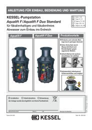
KESSEL-Pumpstation Aqualift€F/Aqualift€F Duo For all wastewaters ...
KESSEL-Pumpstation Aqualift€F/Aqualift€F Duo For all wastewaters ...
KESSEL-Pumpstation Aqualift€F/Aqualift€F Duo For all wastewaters ...

Create successful ePaper yourself
Turn your PDF publications into a flip-book with our unique Google optimized e-Paper software.
3. Technical data<br />
3.2 Switching levels. Separate power source with blue cables and float switches<br />
Chamber 800 Chamber 1000<br />
Vol (l) difference (approx) Height difference (cm) Vol (l) difference (approx) Height difference (cm)<br />
Single Pump Unit<br />
Off – On 150 31 230 31<br />
On – Alarm 90 20 150 20<br />
Double Pump Unit<br />
Off – On1 - - 200 31<br />
On1 – On2 - - 70 10<br />
On2 – Alarm - - 70 10<br />
The alarm levels are located approximately at the base of the inlet level.<br />
3.3 Electrical control unit with separate power source<br />
according to ATEX.<br />
3.3.1 General technical data<br />
Required Fuse –<br />
max 16 Amp / phase (provided on-site)<br />
3.3.2 Control Unit Protection<br />
IP 56 based on appropriate inst<strong>all</strong>ation and securely closed<br />
see-thru cover<br />
IP 21 – without see-thru cover and standard w<strong>all</strong> inst<strong>all</strong>ation<br />
3.3.3 Appropriate use<br />
Information concerning the appropriate use of<br />
the control unit in areas at risk of explosion.<br />
The control unit is designed to operate <strong>KESSEL</strong> single or<br />
double pump lifting stations with the use of float switches.<br />
The control is to be inst<strong>all</strong>ed outside of the area designated<br />
as at risk of explosion.<br />
Classifications<br />
II (1) G [EEx ia] IIC/IIB<br />
(Group II, Category (1)G, designated<br />
for use in gaseous atmospheres)<br />
The requirements of Norms EN 50014:1997 + A1 – A2, EN<br />
50020:2002 have been fulfilled.<br />
EG – Certification<br />
LCIE 06 ATEX 6043X<br />
Identification<br />
II (1) G [EEx ia] IIC/II B 0081 Ta = 0 ... + 50°C<br />
Inst<strong>all</strong>ation / Commissioning<br />
The lifting stations must be inst<strong>all</strong>ed, connected and commissioned<br />
only by a licensed professional. This professional must be trained<br />
and certified in areas including types of ignition, regulations and<br />
work in areas at risk of explosion. Check to make sure that the<br />
pump classification (listed above) satisfies the requirements of the<br />
inst<strong>all</strong>ation area.<br />
• Temperatures in the immediate area of the pumping station<br />
must remain between<br />
0 – 50 deg Celsius (32 – 122 deg F).<br />
Electrical data / Connections<br />
Power supply – 3 x 400 Volt (AC) / 50 Hz +- 10%<br />
Jacks – N, L1, L2, L3 PE) 230 V (AC) / 50 Hz +- 10% to<br />
supply electronics<br />
Um = 253 V<br />
Based on type – max 11 VA<br />
(Electronic with protection)<br />
up to max 16 VA (Electronic with<br />
protection)<br />
Incoming power<br />
Switch contact U=24V, I=20mA<br />
(jacks TF, TF1, TF2, E7,<br />
E8, E9, E10, based on model) PTC – switch Um = 253 V<br />
Exiting power<br />
(Jacks N, L1)<br />
(Jacks L1, L2, L3)<br />
U = 230 V +- 10%, 2A, 50 Hz<br />
(Warning, Relay) Um = 253 V<br />
U = 400 V +- 10%, less then or<br />
equal to 4KW, 50 Hz<br />
(motor protection switch).<br />
8