Compression Springs As Specified In EN - KISSsoft AG
Compression Springs As Specified In EN - KISSsoft AG
Compression Springs As Specified In EN - KISSsoft AG

You also want an ePaper? Increase the reach of your titles
YUMPU automatically turns print PDFs into web optimized ePapers that Google loves.
<strong>KISSsoft</strong> <strong>AG</strong> - +41 55 254 20 50<br />
Uetzikon 4 - +41 55 254 20 51<br />
8634 Hombrechtikon - info@<strong>KISSsoft</strong>. <strong>AG</strong><br />
Switzerland - www. <strong>KISSsoft</strong>. <strong>AG</strong><br />
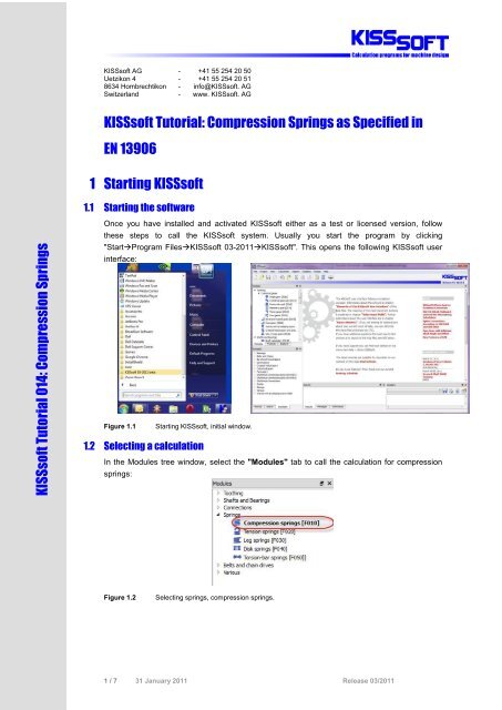
<strong>KISSsoft</strong> Tutorial: <strong>Compression</strong> <strong>Springs</strong> as <strong>Specified</strong> in<br />
<strong>EN</strong> 13906<br />
1 Starting <strong>KISSsoft</strong><br />
1.1 Starting the software<br />
<strong>KISSsoft</strong> Tutorial 014: <strong>Compression</strong> <strong>Springs</strong><br />
Once you have installed and activated <strong>KISSsoft</strong> either as a test or licensed version, follow<br />
these steps to call the <strong>KISSsoft</strong> system. Usually you start the program by clicking<br />
"StartProgram Files<strong>KISSsoft</strong> 03-2011<strong>KISSsoft</strong>". This opens the following <strong>KISSsoft</strong> user<br />
interface:<br />
Figure 1.1 Starting <strong>KISSsoft</strong>, initial window.<br />
1.2 Selecting a calculation<br />
<strong>In</strong> the Modules tree window, select the "Modules" tab to call the calculation for compression<br />
springs:<br />
Figure 1.2<br />
Selecting springs, compression springs.<br />
1 / 7 31 January 2011 Release 03/2011
2 Analyzing <strong>Compression</strong> <strong>Springs</strong><br />
2.1 Task<br />
To analyze a cold formed compression spring 4 x 40 x 235 made of spring steel. Search for this<br />
data:<br />
Spring rate R<br />
Shear stress ô k2 at F 2 =300N<br />
Spring travel s h<br />
This tutorial then describes how you input the following data:<br />
Wire diameter d 4.0 mm<br />
Coil diameter D 40.0 mm<br />
Effective coils n 12.5 mm<br />
Spring length L 0<br />
235.0 mm<br />
Material<br />
Wire C (DIN 17223-1), untreated<br />
Ends of spring<br />
Even<br />
Tolerances DIN 2095 quality standard 1<br />
Table 2.1<br />
Geometry.<br />
Spring force F 1<br />
150 N<br />
Spring force F 2<br />
300 N<br />
Operating temperature 20.0 °C<br />
Stress<br />
dynamic<br />
Support<br />
fixed/ fixed<br />
Table 2.2<br />
Operating data.<br />
2.2 <strong>In</strong>putting operating data<br />
<strong>As</strong> shown below, you can input operating data directly in the input window. Here you can input<br />
either the forces or the ways.<br />
Figure 2.1<br />
<strong>In</strong>put window, "Operating data" group.<br />
The types of support are displayed in a help graphic that you open by clicking next to the<br />
Support field. The support coefficient v is used for calculating the buckling spring travel sk. If<br />
the required level of buckling safety is not achieved, the spring must be led, otherwise it will<br />
buckle.<br />
If the spring must be led, the <strong>KISSsoft</strong> system issues a warning message when you perform<br />
the calculation to inform you of this fact.<br />
2 / 7 31 January 2011 Release 03/2011
Figure 2.2<br />
Warning shown if the spring will buckle and must be led.<br />
Figure 2.3<br />
Types of support with the corresponding support coefficients.<br />
2.3 <strong>In</strong>putting the geometry and selecting materials<br />
The <strong>KISSsoft</strong> database includes a wide range of different compression springs, all of which<br />
correspond to the specifications in DIN 2098, supplementary sheet 1. You can select the spring<br />
you require directly from this list. This example uses a spring selected from this list.<br />
However, if the spring you require is not present, simply select "Own <strong>In</strong>put" and input your<br />
own parameters for a spring. You will find more detailed information about this below.<br />
To find a suitable spring, first click "Update". The system now calculates and displays values<br />
that match your input, such as spring travel, spring forces. This helps you make the best<br />
possible choice.<br />
Click the right-hand mouse button in the spring selection list to determine which values are to<br />
be displayed.<br />
Figure 2.4<br />
<strong>In</strong>put window, "Geometry" group - spring selection.<br />
You can then either select or input the shape of the spring ends, the manufacturing method and<br />
the tolerances in the area below the table.<br />
3 / 7 31 January 2011 Release 03/2011
Figure 2.5<br />
Clicking the right-hand mouse button to select the values to be displayed.<br />
You can select the material either from a drop-down list or input your own values. If you set the<br />
flag in the "shot peened" checkbox, the calculation will take into account the fact that the<br />
spring has been shot peened.<br />
Figure 2.6<br />
Selecting the material.<br />
2.4 Calculation<br />
After you have input all the necessary data, either click<br />
calculate and then display the values.<br />
in the tool bar or press "F5" to<br />
Figure 2.7<br />
Calculating the compression spring.<br />
The results show, among other things, the relevant spring rate. These values are displayed in<br />
the lower right-hand part of the graphic. The system provides a graphic for the force travel<br />
diagram and, for dynamic loads, a Goodman diagram (if a suitable diagram is not present, one<br />
will be approximated). To increase the scale of the graphic, click the enlarge button (right-hand<br />
marking).<br />
Figure 2.8 Force-path diagram. Figure 2.9 Goodman diagram.<br />
4 / 7 31 January 2011 Release 03/2011
To get an overview of all the values, create a report by either clicking<br />
"F6".<br />
or pressing<br />
5 / 7 31 January 2011 Release 03/2011
<strong>Compression</strong> springs [F010]<br />
Calculation method: <strong>EN</strong> 13906-1 (2002)<br />
INPUTS:<br />
Spring geometry<br />
Wire diameter (mm) [d] 4.000<br />
Tolerance analog to DIN 2076 C (mm) [Tol_d] 0.025<br />
Coil diameter (mm) [D] 40.000<br />
<strong>In</strong>ner diameter (mm) [Di] 36.000<br />
External diameter (mm) [De] 44.000<br />
Length of relaxes spring (mm) [L0] 235.000<br />
Effective coils [n] 12.500<br />
Stiff coils [nu] 2.000<br />
Total number of coils [nt] 14.500<br />
Spring ends<br />
surface flattened<br />
Bearings coefficient 0.500<br />
Material<br />
Material wire C (DIN 17223-1)<br />
cold shaped<br />
not shot peened<br />
Shearing modulus at 20°C (N/mm²) [G20] 81500.000<br />
Tensile strength (N/mm²) [Rm] 1726.000<br />
Shearing Modulus depending on temperature (1/°C) [alphaE] -0.00028<br />
Load<br />
Lower spring force (N) [F1] 150.000<br />
Higher spring force (N) [F2] 300.000<br />
Operating temperature (°C) [TB] 20.000<br />
dynamic loading<br />
RESULTS:<br />
Spring rate (N/mm) [R] 3.260<br />
Maximal usable length (mm) [Ln] 77.113<br />
Maximum spring travel (mm) [sn] 157.887<br />
Sum of minimal distance [Sa] 18.750<br />
Shear stress at Fn (N/mm²) [taun] 819.192<br />
Force for maximal spring-travel (N) [Fn] 514.713<br />
Theoretical force at length of block (N) [Fcth] 575.838<br />
Block length (mm) [Lc] 58.363 (- 0.362)<br />
Shear stress at block length (N/mm²) [tauc] 916.475<br />
Permissible shear stress at block length (N/mm²) [tauc_zul] 967.000<br />
Stress coefficient [kappa] 1.135<br />
Travel tension [taukh] 270.994<br />
Permissible travel tension (N/mm²) [taukh_zul] 321.103<br />
The spring is safe for buckling in the used range<br />
Spring travel for buckling (mm) [sk] 101.548<br />
Spring force for buckling (N) [Fk] 331.047<br />
Shear modulus at service temperature (°C) [G] 81500.000<br />
Diameter increase (mm) [DeltaD] 0.698<br />
Eigen frequency (Hz) [fe] 72.548<br />
Mass (g) [mass] 181.184<br />
Load 1<br />
Spring force (N) [F1] 150.000<br />
Spring travel (mm) [s1] 46.012<br />
Spring length (mm) [L1] 188.988<br />
Shear stress (N/mm²) [tau1] 238.732<br />
Adjusted shear stress (N/mm²) [tau1k] 270.994<br />
Load 2<br />
Spring force (N) [F2] 300.000<br />
6 / 7 31 January 2011 Release 03/2011
Spring travel (mm) [s2] 92.025<br />
Spring length (mm) [L2] 142.975<br />
Shear stress (N/mm²) [tau2] 477.465<br />
Adjusted shear stress (N/mm²) [tau2k] 541.987<br />
Relaxation (F2,48h) (%) [Rx] 1.132<br />
Spring force after 48h (N) [F2Rx] 296.605<br />
Utilization of shear stress (static) 0.494<br />
Utilization of shear stress (dynamic) 0.844<br />
Tolerances<br />
according to DIN <strong>EN</strong> 15800 quality standard<br />
1<br />
Permissible deviation from<br />
Coil diameter (mm) [AD] 0.300<br />
Lower spring force (N) [AF1] 11.300<br />
Higher spring force (N) [AF2] 12.800<br />
Spring length (mm) [AL0] 3.050<br />
Perpendicular line (mm) [e1] 7.050<br />
Parallel line (mm) [e2] 0.660<br />
2.5 <strong>In</strong>putting your own spring data<br />
If you want to analyze a special spring, or a spring that is not already present, click "Own<br />
<strong>In</strong>put" and input your own values. Here, you can also use the spring rate (R=ÄF/Äs) to size the<br />
wire diameter and the effective coils.<br />
Figure 2.10<br />
<strong>In</strong>putting spring geometry.<br />
Figure 2.11<br />
Sizing the wire diameter.<br />
7 / 7 31 January 2011 Release 03/2011