KISSsoft Tutorial: Cylindrical Gear Pair 1 Problem K ISSsoft Tutorial ...
KISSsoft Tutorial: Cylindrical Gear Pair 1 Problem K ISSsoft Tutorial ...
KISSsoft Tutorial: Cylindrical Gear Pair 1 Problem K ISSsoft Tutorial ...

Create successful ePaper yourself
Turn your PDF publications into a flip-book with our unique Google optimized e-Paper software.
<strong>K<strong>ISSsoft</strong></strong> <strong>Tutorial</strong>: <strong>Cylindrical</strong> <strong>Gear</strong> <strong>Pair</strong><br />
__________________________________________________________________________________________<br />
Für Release 03/2008<br />
Letzte Änderung 14.06.2008 00:06:00<br />
__________________________________________________________________________________________<br />
<strong>K<strong>ISSsoft</strong></strong> <strong>Tutorial</strong> 008: <strong>Cylindrical</strong> <strong>Gear</strong> <strong>Pair</strong><br />
1 <strong>Problem</strong><br />
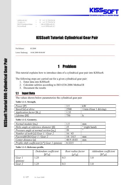
This tutorial explains how to introduce data of a cylindrical gear pair into <strong>K<strong>ISSsoft</strong></strong>.<br />
The following steps are carried out for a given cylindrical gear pair:<br />
1. Enter data into <strong>K<strong>ISSsoft</strong></strong><br />
2. Calculate safeties according to ISO 6336:2006 Method B<br />
3. Document the results<br />
1.1 Input Data<br />
The values shown below parameterize the cylindrical gear pair<br />
Table 1.1-1. Strength.<br />
Power [P] 3.5 kW<br />
Speed [n] at drive 2500 1/min (<strong>Gear</strong> 1 driving)<br />
Application factor [K A ] 1.35<br />
Lifetime [H] 750 h<br />
Table 1.1-2. Geometry.<br />
Normal module [m n ] 1.5 mm<br />
Helix angle at reference diameter [â] 25 ° (right hand)<br />
Pressure angle at normal section [ n ] 20 °<br />
Number of teeth [z] <strong>Gear</strong> 1 / <strong>Gear</strong> 2 16 / 43<br />
Facewidth [b] <strong>Gear</strong> 1 / <strong>Gear</strong> 2 14 / 14.5 mm<br />
Center distance [a] 48.9 ±0.03 mm<br />
Profile shift coefficient [x*] <strong>Gear</strong> 1 (pinion) 0.3215<br />
Table 1.1-3. Reference profile.<br />
Dedendum coefficient<br />
[h* fP ]<br />
Root radius factor<br />
[* fP ]<br />
Addendum coefficient<br />
[h* aP ]<br />
<strong>Gear</strong> 1 1.25 0.3 1.0<br />
(pinion)<br />
<strong>Gear</strong> 2 1.25 0.3 1.0<br />
1 / 17 14. Juni 2008
Table 1.1-4. Material and Lubrication.<br />
Material Data on hardness Flim Hlim Lub.<br />
<strong>Gear</strong> 1 15 CrNi 6 case-hardened HRC 60 430 N/mm 2 1500 N/mm 2 Grease,<br />
<strong>Gear</strong> 2 15 CrNi 6 case-hardened HRC 60 430 N/mm 2 1500 N/mm 2 GB00,<br />
(pinion)<br />
Microlube<br />
80 °C<br />
Table 1.1-5. Tolerances.<br />
No. of teeth spanned<br />
[k]<br />
Max. base tangent length<br />
[W k,max ]<br />
Min. base tangent length<br />
[W k,min ]<br />
<strong>Gear</strong> 1 (pinion) 3 11.782 mm 11.758 mm<br />
<strong>Gear</strong> 2 6 25.214 mm 25.183 mm<br />
Table 1.1-6. Specifications.<br />
Quality [Q] 8 / 8 (DIN 3961)<br />
Lead correction<br />
End relief<br />
Position of contact pattern not verified or inappropriate<br />
Type of pinion shaft<br />
Fig. 1.1-1. Load case of pinion shaft (see ISO 6336:2006, Fig. 13a)<br />
l = 53 mm; s = 5.9 mm; d sh = 14 mm<br />
no support effect<br />
2.1 Starting the Program<br />
2 Solution<br />
Upon installation and activation of the license <strong>K<strong>ISSsoft</strong></strong> is started via Start>Programs><strong>K<strong>ISSsoft</strong></strong><br />
03-2008/<strong>K<strong>ISSsoft</strong></strong>. The main window opens (see Fig. 2.1-1).<br />
2 / 17
2.2 Starting the Calculation Module<br />
Fig. 2.1-1. <strong>K<strong>ISSsoft</strong></strong> main window.<br />
Start the <strong>Cylindrical</strong> <strong>Gear</strong> pair calculation module by double-clicking the appropriate entry within<br />
the Modules window in the upper left corner of the main window.<br />
Fig. 2.2-1. Select <strong>Cylindrical</strong> <strong>Gear</strong> pair calculation module from Modules window.<br />
The Basic data input window opens (see Fig. 2.2-2).<br />
3 / 17
Fig. 2.2-2. Basic data input window of <strong>Cylindrical</strong> <strong>Gear</strong> pair calculation module.<br />
The following sections deal with parameterizing the gear pair.<br />
2.3 Geometry of the <strong>Gear</strong> <strong>Pair</strong><br />
The data given in Table 1.1-2 along with the value for Quality in Table 1.1-6 is entered into<br />
group Geometry of tab Basic data. Since the profile shift coefficient of gear 2 is computed from<br />
center distance and profile shift coefficient of gear 1 it cannot be entered into the input field.<br />
Clicking the button right next to the Profile shift coefficient input field opens the Sizing of<br />
profile shift coefficient window which enables you to have the profile shift coefficients<br />
calculated according to a given criterion, e.g. optimum specific sliding.<br />
According to Table 1.1-6 the Quality value refers to DIN 3961. By default, if the calculation<br />
method is set to ISO the Quality value refers to ISO, too. Likewise, if the calculation method is<br />
set to DIN the Quality value refers to DIN. The problem that we face here is that a strength<br />
calculation method according to ISO has to be combined with a quality value according to DIN.<br />
We can bypass the standard mapping by clicking the menu Calculation>Settings in the menu bar.<br />
The Module specific settings window opens (see Fig. 2.3-1). Choose the option DIN3961-3963<br />
4 / 17
from the drop-down list Input of quality according to and have <strong>K<strong>ISSsoft</strong></strong> map the Quality value<br />
according to DIN while the strength calculation is carried out according to ISO.<br />
Fig. 2.3-1. Quality mapping in Module specific settings window.<br />
Note that some of the input fields come with the convert button ( ). Clicking this button opens<br />
a dialog window which enables you to calculate the respective value based on one or more other<br />
values. Take the input field Normal module, for example. If the only thing you know is the value<br />
for the Transverse diametral pitch you may click the button. The Convert normal module<br />
window opens and offers you a list of alternative values to choose from. Select the desired value<br />
by placing a checkmark in the checkbox adjacent to the input field and enter your digits. Click<br />
the Calculate button to convert the given value into normal module and confirm with Accept<br />
afterwards. The result is taken over into the Normale module input field.<br />
Fig. 2.3-2. Convert normal module window.<br />
There are some input fields that expect values which refer to angles, e.g. Pressure angle at<br />
normal section. Right-clicking these input fields opens a dialog which allows the definition of<br />
degree-minutes and degree-seconds instead of decimals (see Fig. 2.3-3).<br />
5 / 17
Fig. 2.3-3. Dialog window for definition of angle decimals.<br />
2.4 Definition of Power Data and Calculation Method<br />
In the Basic data input window you can find the group Strength. Therein, define required<br />
Lifetime (H = 750h), Application factor (K A = 1.35) and kinematics : torque is defined via Power<br />
(P = 3.5kW) and Speed (n = 2500 1/min). If, for any reason, torque was known instead of power<br />
the radio button next to the input field Power must be activated. An active radio button marks<br />
the respective value to be evaluated from the two others. Tell <strong>K<strong>ISSsoft</strong></strong> which gear you are<br />
refering the power data to by choosing the appropriate index from the drop-down list Reference<br />
gear. Here it is <strong>Gear</strong> 1 (pinion).<br />
The problem description requires the calculation carried out according to ISO. Therefore choose<br />
ISO 6336 :2006 Method B from the drop-down list Calculation method.<br />
Fig. 2.4-1. Group Strength in tab Basic data.<br />
If you know the value for the Face load factor K Hß 1 you may enter it directly in the respective<br />
input field. Before doing so you have to activate it by placing a checkmark into the checkbox<br />
right next to the input field. Generally, however, the face load factor is not known and must be<br />
evaluated from other parameters: open the Define face load factor window by clicking the<br />
button right next to the input field Face load factor and parameterize the dialog window as<br />
follows :<br />
1. The drop-down list Lead correction has to be set to End relief according to Table 1.1-6.<br />
2. Choose the option ISO6336 picture 13a from the drop-down list Type of pinion shaft.<br />
3. Enter the values Bearing span (l = 53mm), Span 2 (s = 5.9mm) and Outside diameter (d sh<br />
= 14mm) in group Pinion shaft according to Table 1.1-6.<br />
4. Since the pinion has no support effect and position of contact pattern is not verified or<br />
inappropriate the respective drop-down lists have to be chosen accordingly.<br />
The readily parameterized dialog window is shown in Fig. 2.4-2.<br />
1 The face load factor K Hâ is a measure for non-linearity of load distribution along the face width.<br />
2 Activate this input field by first placing a checkmark into the checkbox next to it.<br />
6 / 17
Fig. 2.4-2. Definition of face load factor.<br />
Hint:<br />
According to ISO 6336:2006 there are five different contact patterns to be distinguished.<br />
Clicking the<br />
button displays them in the Information window.<br />
Fig. 2.4-3. Information window on contact patterns.<br />
2.5 Material and Lubrication<br />
From the drop-down lists <strong>Gear</strong> 1 and <strong>Gear</strong> 2 in group Material and lubrication in tab Basic data<br />
choose the same material 15 CrNi 6. Lubricant is required to be Grease: Microlube GB 00.<br />
Choose it from the Lubrication drop-down lists. The button next to the right-hand dropdown<br />
list enables you to define the lubricant temperature which equals the operating temperature<br />
of the gear. Lubricant temperature has a major effect on effective viscosity where in case of<br />
grease and oil lubrication the ambient temperature is of no interest. Note that in case of plastic<br />
gears the choice of lubricant temperature has an effect on the strength of the material.<br />
7 / 17
Fig. 2.5-1. Definition of material, lubrication and lubricant temperature.<br />
2.6 Reference Profile<br />
Reference profile data as seen in Table 1.1-3 can be entered into the Reference profile input<br />
window. Choose it from the tabs at top of the input window.<br />
Fig. 2.6-1. Reference profile tab at top of the input window.<br />
8 / 17
2.7 Tolerances<br />
Fig. 2.6-2. Input window Reference profile.<br />
Tooth thickness deviations are defined in the tab Tolerances (Fig. 2.7-1). It is activated in the<br />
same manner as the tab Reference profile described in the previous section.<br />
9 / 17
Fig. 2.7-1. Input window Tolerances.<br />
In the majority of cases only the effective base tangent length deviations and number of teeth<br />
spanned are given. That is why <strong>K<strong>ISSsoft</strong></strong> offers the conversion tool Convert tooth thickness<br />
deviations for <strong>Gear</strong> 1 (2). Activate it by clicking the button on the right-hand side of the<br />
input field Tooth thickness deviation (upper/lower) as shown in Fig. 2.7-2. Enter number of teeth<br />
spanned and upper and lower limits of base tangent length. Click Calculate and then Accept to<br />
take over the results for the tooth thickness tolerances.<br />
Fig. 2.7-2. Conversion tool Convert tooth thickness deviations for <strong>Gear</strong> 1(2).<br />
10 / 17
The tab Tolerances is also used for defining deviations of center distance in group Center<br />
distance. You may either choose deviations by category via the dropdownlist Center distance<br />
tolerance or define your own limits. Choose Own Input from the drop-down list therefore.<br />
Remarks:<br />
1. Set deviations after definition of the profile shift coefficients for both gears. Otherwise<br />
sizing has to be redone.<br />
2. Change the number of spanned teeth by placing a checkmark into the checkbox next to<br />
the input field No of spanned teeth in group Settings and entering the new value.<br />
2.8 Calculation<br />
Click in the tool bar or press F5 to carry out the strength calculation. For the given scenario<br />
an Information window opens with following message:<br />
If necessary, test if this is actually the case. The final results for strength calculation are given in<br />
Fig. 2.8-1.<br />
Fig. 2.8-1. Final results.<br />
2.9 Report<br />
Clicking the<br />
button or pressing F6 creates a report of the calculation:<br />
<strong>K<strong>ISSsoft</strong></strong> - Release 03-2008<br />
<strong>K<strong>ISSsoft</strong></strong> Evaluationsversion<br />
File<br />
Name : <strong>Tutorial</strong>-008_ISO<br />
Changed by : mh on: 14.06.2008 at: 00:03:26<br />
Important hint: At least one warning has occurred during the calculation:<br />
1-> Indication:<br />
With the setting 'Position of the contact pattern: unfavorable'<br />
unrealistic high face load coefficient KHb is given for gears with flank line corrections.<br />
CALCULATION OF A HELICAL GEAR PAIR<br />
11 / 17
Drawing or article number:<br />
<strong>Gear</strong> 1: 0.000.0<br />
<strong>Gear</strong> 2: 0.000.0<br />
Calculation-method ISO 6336:2006 Method B<br />
------- GEAR 1 -------- GEAR 2 --<br />
Nominal power (kW) [P] 3.500<br />
Speed (1/min) [n] 2500.0 930.2<br />
Torque (Nm) [T] 13.4 35.9<br />
Application factor [KA] 1.35<br />
Service life in hours [H] 750.00<br />
<strong>Gear</strong> driving (+) / driven (-) + -<br />
1. TOOTH GEOMETRY AND MATERIAL<br />
(Geometry calculation according ISO 21771)<br />
------- GEAR 1 -------- GEAR 2 --<br />
Centre distance (mm) [a] 48.900<br />
Centre distance tolerances<br />
ISO 286 Measure js9<br />
Normal module (mm) [mn] 1.5000<br />
Pressure angle at normal section (°) [alfn] 20.0000<br />
Helix angle at Pitch diameter (°) [beta] 25.0000<br />
Number of teeth [z] 16 43<br />
Facewidth (mm) [b] 14.00 14.50<br />
Helix right left<br />
Accuracy grade [Q-ISO1328] 8 8<br />
Inner diameter of ring (mm) [dRing] 0.00 0.00<br />
Internal diameter gearbody (mm) [di] 0.00 0.00<br />
Material<br />
<strong>Gear</strong> 1:<br />
<strong>Gear</strong> 2:<br />
15 CrNi 6, Case-carburized steel, case-hardened<br />
ISO 6336-5 Figure 9/10 (MQ), core strength >=25HRC Jominy J=12mm=25HRC Jominy J=12mm=0.85)<br />
Fatigue str. tooth root tension (N/mm²) [sigFlim] 430.00 430.00<br />
Fatigue str. Hertzian stress (N/mm²) [sigHlim] 1500.00 1500.00<br />
Tensile strength (N/mm²) [Rm] 1000.00 1000.00<br />
Yield point (N/mm²) [Rp] 685.00 685.00<br />
Youngs modulus (N/mm²) [E] 206000 206000<br />
Poisson's ratio [ny] 0.300 0.300<br />
Average roughness, Ra, tooth flank (µm) [RAH] 0.60 0.60<br />
Mean roughness height, Rz, flank (µm) [RZH] 4.80 4.80<br />
Mean roughness height, Rz, root (µm) [RZF] 20.00 20.00<br />
Tool or reference profile of gear 1 :<br />
Reference Profile<br />
1.25 / 0.30 / 1.0 ISO 53.2 Profil B<br />
Addendum factor [haP*] 1.000<br />
Dedendum coefficient [hfP*] 1.250<br />
Tip radius factor [rhoaP*] 0.000<br />
Root radius factor [rhofP*] 0.300<br />
Addendum form factor [hFaP*] 0.000<br />
Protuberance height factor [hprP*] 0.000<br />
Protuberance angle [alfprP] 0.000<br />
Ramp angle [alfKP] 0.000<br />
not topping<br />
Tool or reference profile of gear 2 :<br />
Reference Profile<br />
1.25 / 0.30 / 1.0 ISO 53.2 Profil B<br />
Addendum factor [haP*] 1.000<br />
Dedendum coefficient [hfP*] 1.250<br />
Tip radius factor [rhoaP*] 0.000<br />
Root radius factor [rhofP*] 0.300<br />
Addendum form factor [hFaP*] 0.000<br />
Protuberance height factor [hprP*] 0.000<br />
Protuberance angle [alfprP] 0.000<br />
Ramp angle [alfKP] 0.000<br />
not topping<br />
Sum of reference profile gears:<br />
Dedendum reference profile (module) [hfP*] 1.250 1.250<br />
Tooth root radius Refer. profile (module)<br />
12 / 17
[rofP*] 0.300 0.300<br />
Addendum Reference profile (module) [haP*] 1.000 1.000<br />
Protuberance height (module) [hk*] 0.000 0.000<br />
Protuberance angle (°) [alfPro] 0.000 0.000<br />
Buckling root flank height (module) [hko*] 0.000 0.000<br />
Buckling root flank angle (°) [alfnk] 0.000 0.000<br />
Type of profile modification:<br />
No<br />
Tip relief (µm) [Ca] 2.00 2.00<br />
Type of lubrication<br />
Grease lubrication<br />
Grease Grease: Microlube GB 0<br />
Lubricant base<br />
Mineral-oil base<br />
Kinem. viscosity base oil at 40 °C (mm²/s) [nu40] 400.00<br />
Kinem. viscosity base oil at 100 °C (mm²/s) [nu100] 25.00<br />
FZG-Test A/8.3/90 step [FZGtestA] 12<br />
Specific density at 15 °C (kg/dm³) [roOil] 0.900<br />
Grease temperature (°C) [TS] 80.000<br />
ambient temperature (°C) [TU] 20.000<br />
------- GEAR 1 -------- GEAR 2 --<br />
Overall transmission ratio [itot] -2.688<br />
<strong>Gear</strong> ratio [u] 2.688<br />
Transverse module (mm) [mt] 1.655<br />
Pressure angle at Pitch circle (°) [alft] 21.880<br />
Working transverse pressure angle (°) [alfwt] 22.100<br />
[alfwt.e/i] 22.189 / 22.010<br />
Working pressure angle at normal section (°) [alfwn] 20.199<br />
Helix angle at operating pitch diameter (°)<br />
[betaw] 25.034<br />
Base helix angle (°) [betab] 23.399<br />
Reference centre distance (mm) [ad] 48.824<br />
Sum of the Addendum modification [Summexi] 0.0506<br />
Profile shift coefficient [x] 0.3215 -0.2709<br />
Tooth thickness (Arc) (module) [sn*] 1.8048 1.3736<br />
Modification of tip diam. (mm) [k*mn] 0.000 0.000<br />
Reference diameter (mm) [d] 26.481 71.168<br />
Base diameter (mm) [dB] 24.573 66.041<br />
Tip diameter (mm) [da] 30.446 73.355<br />
(mm) [da.e/i] 30.446 / 30.436 73.355 / 73.345<br />
Tip diameter tolerance (mm) [Ada.e/i] 0.000 / -0.010 0.000 / -0.010<br />
Tip chamfer/ tip rounding (mm) [Fased] 0.000 0.000<br />
Tip form circle (mm) [dFa] 30.446 73.355<br />
(mm) [dFa.e/i] 30.446 / 30.436 73.355 / 73.345<br />
Operating pitch diameter (mm) [dw] 26.522 71.278<br />
(mm) [dw.e/i] 26.539 / 26.505 71.323 / 71.233<br />
Root diameter (mm) [df] 23.696 66.605<br />
Generating Profile shift coefficient [xE.e/i] 0.2601 / 0.2367 -0.3275 / -0.3577<br />
Manufactured root diameter with xE (mm) [df.e/i] 23.511 / 23.441 66.436 / 66.345<br />
Theoretical tip clearence (mm) [c] 0.375 0.375<br />
Effective tip clearence (mm) [c.e/i] 0.541 / 0.428 0.538 / 0.436<br />
Active root diameter (mm) [dNf] 25.050 68.670<br />
(mm) [dNf.e/i] 25.087 / 25.019 68.720 / 68.625<br />
Root form circle (mm) [dFf] 24.894 67.921<br />
(mm) [dFf.e/i] 24.820 / 24.794 67.816 / 67.761<br />
Reserve (dNf-dFf)/2 (mm) [rNf-rFf.e/i] 0.147 / 0.099 0.480 / 0.405<br />
Addendum (mm) [ha] 1.982 1.094<br />
(mm) [ha.e/i] 1.982 / 1.977 1.094 / 1.089<br />
Dedendum (mm) [hf] 1.393 2.281<br />
(mm) [hf.e/i] 1.485 / 1.520 2.366 / 2.411<br />
Roll angle at dFa (°) [xsi_dFa.e/i] 41.909 / 41.870 27.702 / 27.682<br />
Roll angle to dNf (°) [xsi_dNf.e/i] 11.778 / 10.956 16.485 / 16.184<br />
Roll angle to dNa (°) [xsi_dNa.e/i] 41.909 / 41.870 27.702 / 27.682<br />
Roll angle to dNf (°) [xsi_dNf.e/i] 11.778 / 10.956 16.485 / 16.184<br />
Roll angle at dFf (°) [xsi_dFf.e/i] 8.135 / 7.696 13.371 / 13.160<br />
Tooth depth (mm) [H] 3.375 3.375<br />
Virtual gear no. of teeth [zn] 20.960 56.329<br />
Normal Tooth thickness at Tip cyl. (mm) [san] 0.874 1.225<br />
(mm) [san.e/i] 0.806 / 0.771 1.166 / 1.127<br />
Normal Tooth space as Tip cylinder (mm) [efn] 0.000 1.352<br />
(mm) [efn.e/i] 0.000 / 0.000 1.388 / 1.409<br />
Max. sliding speed at tip (m/s) [vga] 1.436 0.919<br />
Specific sliding at the tip [zetaa] 0.610 0.591<br />
Specific sliding at the root [zetaf] -1.443 -1.567<br />
Sliding factor on tip [Kga] 0.414 0.265<br />
Sliding factor on root [Kgf] -0.265 -0.414<br />
Pitch (mm) [pt] 5.200<br />
Base pitch (mm) [pbt] 4.825<br />
13 / 17
Transverse pitch on contact-path (mm) [pet] 4.825<br />
Lead height (mm) [pz] 178.408 479.470<br />
Axial pitch (mm) [px] 11.150<br />
Length of path of contact (mm) [ga, e/i] 6.555 ( 6.638 / 6.453)<br />
Length T1-A, T2-A (mm) [T1A, T2A] 2.432( 2.349/ 2.526) 15.965(15.965/15.954)<br />
Length T1-B (mm) [T1B, T2B] 4.162( 4.162/ 4.154) 14.235(14.152/14.326)<br />
Length T1-C (mm) [T1C, T2C] 4.989( 4.967/ 5.011) 13.408(13.348/13.468)<br />
Length T1-D (mm) [T1D, T2D] 7.257( 7.174/ 7.351) 11.140(11.140/11.129)<br />
Length T1-E (mm) [T1E, T2E] 8.987( 8.987/ 8.979) 9.410( 9.327/ 9.501)<br />
Length T1-T2 (mm) [T1T2] 18.397 (18.314 / 18.479)<br />
Diameter of single contact point B (mm)<br />
[d-B] 25.945(25.945/25.940) 71.916(71.851/71.988)<br />
Diameter of single contact point D (mm)<br />
[d-D] 28.540(28.456/28.635) 69.698(69.698/69.691)<br />
Addendum contact ratio [eps] 0.829( 0.833/ 0.822) 0.530( 0.542/ 0.515)<br />
Minimal length of contact line (mm) [Lmin] 19.611<br />
Transverse contact ratio [eps_a] 1.359<br />
Transverse contact ratio, effective [eps_a.e/m/i] 1.376 / 1.357 / 1.337<br />
Overlap ratio [eps_b] 1.256<br />
Total contact ratio [eps_g] 2.614<br />
Total contact ratio, effective [eps_g.e/m/i] 2.631 / 2.612 / 2.593<br />
2. FACTORS OF GENERAL INFLUENCE<br />
------- GEAR 1 -------- GEAR 2 --<br />
Nominal circum. force at pitch circle (N)<br />
[Ft] 1009.7<br />
Axial force (N) [Fa] 470.8<br />
Radial force (N) [Fr] 405.5<br />
Normal force (N) [Fnorm] 1185.6<br />
Tangent.load at p.c.d.per mm (N/mm) (N/mm)<br />
[w] 72.12<br />
Only for information: Forces at the pitch-circle :<br />
Nominal circumferential force (N) [Ftw] 1008.1<br />
Axial force (N) [Faw] 470.8<br />
Radial force (N) [Frw] 409.4<br />
Circumferential speed pitch d.. (m/sec) [v] 3.47<br />
Running in value y.a (µm) [ya] 1.1<br />
Correction coefficient [CM] 0.800<br />
<strong>Gear</strong> body coefficient [CR] 1.000<br />
Reference profile coefficient [CBS] 1.000<br />
Material coefficient [E/Est] 1.000<br />
Singular tooth stiffness (N/mm/µm) [c'] 12.468<br />
Meshing spring stiffness (N/mm/µm) [cgalf] 15.821<br />
Meshing spring stiffness (N/mm/µm) [cgbet] 13.448<br />
Reduced mass (kg/mm) [mRed] 0.002<br />
Resonance speed (min-1) [nE1] 48931<br />
Nominal speed (-) [N] 0.051<br />
Subcritical range<br />
Bearing distance l of pinion shaft (mm) [l] 53.000<br />
Distance s of pinion shaft (mm) [s] 5.900<br />
Outside diameter of the pinion shaft (mm)<br />
[dsh] 14.000<br />
load according ISO 6336/1 Diagram 16 [-] 0<br />
0:a), 1:b), 2:c), 3:d), 4:e)<br />
Coefficient K' following ISO 6336/1 Diagram 13<br />
[K'] 0.80<br />
Without support effect<br />
Tooth trace deviation (active) (µm) [Fby] 15.11<br />
from deformation of shaft (µm) [fsh*B1] 2.56<br />
Tooth trace: End relief<br />
Position of Contact pattern: Without verification or unfavourable<br />
from production tolerances (µm) [fma*B2] 14.36<br />
Tooth trace deviation, theoretical (µm) [Fbx] 17.77<br />
Running in value y.b (µm) [yb] 2.67<br />
Dynamic coefficient [KV] 1.051<br />
Face coefficient - flank [KHb] 1.992<br />
- Tooth root [KFb] 1.692<br />
- Scuffing [KBb] 1.992<br />
Transverse coefficient - flank [KHa] 1.347<br />
- Tooth root [KFa] 1.347<br />
- Scuffing [KBa] 1.347<br />
Helix angle coefficient scuffing [Kbg] 1.242<br />
14 / 17
No of load changes (in mio.) [NL] 112.500 41.860<br />
3. TOOTH ROOT STRENGTH<br />
------- GEAR 1 -------- GEAR 2 --<br />
Calculation of Tooth form coefficients according method: B<br />
(Calculate tooth shape coefficient YF with manufactured addendum mod. xE.e)<br />
Tooth form factor [YF] 1.37 1.67<br />
Stress correction factor [YS] 2.15 1.84<br />
working angle (°) [alfen] 21.64 18.97<br />
Bending lever arm (mm) [hF] 1.52 1.84<br />
Tooth thickness at root (mm) [sFn] 3.14 3.15<br />
Tooth root radius (mm) [roF] 0.65 0.82<br />
(hF* = 1.012/1.225 sFn* = 2.093/2.102 roF* = 0.431/0.545 dsFn = 24.00/67.03 alfsFn =<br />
30.00/30.00)<br />
Contact ratio factor [Yeps] 1.000<br />
Helix angle factor [Ybet] 0.792<br />
Deep tooth factor [YDT] 1.000<br />
<strong>Gear</strong> rim factor [YB] 1.000 1.000<br />
Effective facewidth (mm) [beff] 14.00 14.50<br />
Nominal shear stress at tooth root (N/mm²)<br />
[sigF0] 112.30 113.33<br />
Tooth root stress (N/mm²) [sigF] 363.13 366.46<br />
Permissible bending stress at root of Test-gear<br />
support factor [YdrelT] 0.999 0.994<br />
Surface-factor [YRrelT] 0.957 0.957<br />
Size coefficient (Tooth root) [YX] 1.000 1.000<br />
Limited-life factor [YNT] 0.930 0.949<br />
Alternating bending coefficient [Kwb] 1.000 1.000<br />
Stress correction factor [Yst] 2.00<br />
Limit strength tooth root (N/mm²) [sigFG] 764.63 776.06<br />
Permissible tooth root stress (N/mm²)<br />
[sigFP=sigFG/SFmin] 588.17 596.97<br />
Required safety [SFmin] 1.30 1.30<br />
Safety for Tooth root stress [SF=sigFG/sigF] 2.11 2.12<br />
Transmittable power (kW) [kWRating] 5.67 5.70<br />
4. SAFETY AGAINST PITTING (TOOTH FLANK)<br />
------- GEAR 1 -------- GEAR 2 --<br />
Zone factor [ZH] 2.291<br />
Elasticity coefficient (N^.5/mm) [ZE] 189.812<br />
Contact ratio factor [Zeps] 0.858<br />
Helix angle factor [Zbet] 0.952<br />
Effective facewidth (mm) [beff] 14.00<br />
Nominal flank pressure (N/mm²) [sigH0] 686.65<br />
Surface pressure at Operating pitch diameter (N/mm²)<br />
[sigHw] 1339.84<br />
Single tooth contact factor [ZBD] 1.00 1.00<br />
Surface pressure on flank (N/mm²) [sigH] 1339.84 1339.84<br />
Lubrication factor [ZL] 1.063 1.061<br />
Speed factor [ZV] 0.974 0.975<br />
Roughness factor [ZR] 0.937 0.939<br />
Material mating factor [ZW] 1.000 1.000<br />
Limited-life factor [ZNT] 0.975 1.014<br />
Small amount of pitting permissible (0=no, 1=yes) 0 0<br />
Size coefficient (flank) [ZX] 1.000 1.000<br />
Limit strength pitting (N/mm²) [sigHG] 1420.17 1476.89<br />
Permissible surface pressure (N/mm²) [sigHP=sigHG/SHmin] 1494.92 1554.63<br />
Safety for surface pressure at pitch diameter<br />
[SHw] 1.06 1.10<br />
Required safety [SHmin] 0.95 0.95<br />
Transmittable power (kW) [kWRating] 4.36 4.71<br />
Safety for stress at single tooth contact<br />
[SHBD=sigHG/sigH] 1.06 1.10<br />
(Safety regarding nominal torque) [(SHBD)^2] 1.12 1.22)<br />
5. STRENGTH AGAINST SCUFFING<br />
Calculation method according DIN3990<br />
The calculation of load capacity for scuffing does not cover grease.<br />
The FZG-Test stage [FZGtestA] is only estimated for grease.<br />
The calculation can only serve as a rough guide.!<br />
15 / 17
Lubrication coefficient (Scoring) [XS] 1.200<br />
Relative structure coefficient (Scoring) [XWrelT] 1.000<br />
Therm. contact factor (N/mm/s^.5/K) [BM] 13.795 13.795<br />
Effective facewidth (mm) [beff] 14.000<br />
Applicable circumferential force/tooth width<br />
[wbt] 341.080<br />
Angle factor [Xalfbet] 0.990<br />
(eps1: 0.829, eps2: 0.530)<br />
Flashtemperature-criteria (DIN3990)<br />
Tooth mass temperature (°C) [theM-B] 122.47<br />
theM-B = theoil + XS*0.47*theflamax [theflamax] 75.31<br />
Scuffing temperature (°C) [theS] 401.51<br />
Coordinate gamma (point of highest temp.) [Gamma] 0.455<br />
Highest contact temp. (°C) [theB] 197.78<br />
Flash factor [XM] 50.002<br />
Geometry-factor [XB] 0.215<br />
Distribution factor [XGam] 1.000<br />
Coefficient of friction [mymy] 0.127<br />
Required safety [SBmin] 2.000<br />
Safety coefficient for scuffing (flash-temp)<br />
[SB] 2.729<br />
Integraltemperature-criteria (DIN3990)<br />
Tooth mass temperature (°C) [theM-C] 103.56<br />
theM-C = theoil + XS*0.70*theflaint [theflaint] 28.05<br />
Integral scuffing temperature (°C) [theSint] 401.51<br />
Flash factor [XM] 50.002<br />
Contact ratio factor [Xeps] 0.282<br />
Mean coefficient of friction [mym] 0.099<br />
Geometry-factor [XBE] 0.364<br />
Meshing factor [XQ] 1.000<br />
Tip relief-factor [XCa] 1.000<br />
Integral-tooth flank temperature (°C) [theint] 145.64<br />
Required safety [SSmin] 1.800<br />
Safety coefficient for scuffing (intg.-temp.)<br />
[SSint] 2.757<br />
Safety referring to transfered torque [SSL] 4.898<br />
6. TOOTH THICKNESS DIMENSIONS<br />
------- GEAR 1 -------- GEAR 2 --<br />
Tooth thickness tolerance Own Input Own Input<br />
Tooth thickness allowance (normal section) (mm)<br />
[As.e/i] -0.067 / -0.093 -0.062 / -0.095<br />
No of teeth over which to measure [k] 3.000 6.000<br />
Base tangent length ('span') (no backlash) (mm)<br />
[Wk] 11.845 25.272<br />
Actual base tangent length ('span') (mm) [Wk.e/i] 11.782 / 11.758 25.214 / 25.183<br />
Diameter of contact point (mm) [dMWk.m] 26.843 69.973<br />
Theor. ball/roller diameter (mm) [DM] 2.789 2.496<br />
Actual ball/roller diameter (mm) [DMeff] 3.000 2.500<br />
Theor. dim. centre to ball (mm) [MrK] 16.053 36.846<br />
Actual dimension centre to ball (mm) [MrK.e/i] 15.989 / 15.964 36.760 / 36.714<br />
Diameter of contact point (mm) [dMMr.m] 27.596 70.166<br />
Theor. dimension over two balls (mm) [MdK] 32.107 73.644<br />
Actual dimension over balls (mm) [MdK.e/i] 31.978 / 31.929 73.473 / 73.381<br />
Actual dimension over rolls (mm) [MdR.e/i] 31.978 / 31.929 73.520 / 73.428<br />
Actual dimensions over 3 rolls (mm) [Md3R.e/i] 0.000 / 0.000 73.520 / 73.428<br />
Chordal tooth thickness (no backlash) (mm)<br />
['sn] 2.704 2.060<br />
Actual chordal tooth thickness (mm) ['sn.e/i] 2.637 / 2.611 1.998 / 1.965<br />
Chordal height from da.m (mm) [ha] 2.037 1.103<br />
Tooth thickness (Arc) (mm) [sn] 2.707 2.060<br />
(mm) [sn.e/i] 2.640 / 2.615 1.999 / 1.966<br />
Axial Distance Without Backlash (mm) [aControl.e/i] 48.725 / 48.646<br />
Backlash free centre-distance, Tolerances (mm)<br />
[jta] -0.175 / -0.254<br />
Centre distance deviation (mm) [Aa.e/i] 0.031 / -0.031<br />
Circumferential backlash from Aa (mm) [jt_Aa.e/i] 0.025 / -0.025<br />
Radial clearance (mm) [jr] 0.285 / 0.144<br />
Circumferential backlash (mm) [jt] 0.232 / 0.117<br />
Normal backlash (mm) [jn] 0.198 / 0.100<br />
7. TOLERANCES<br />
16 / 17
------- GEAR 1 -------- GEAR 2 --<br />
According ISO 1328:<br />
Accuracy grade [Q-ISO1328] 8 8<br />
Single pitch deviation (µm) [fpt] 14.00 15.00<br />
Single pitch deviation (µm) [fpb] 13.00 14.00<br />
Cumulative circular pitch error over z/8 pitches (µm)<br />
[Fpz/8] 19.00 24.00<br />
Profile deviation (µm) [ffa] 11.00 13.00<br />
Profile angular deviation (µm) [fHa] 9.50 11.00<br />
Profile total deviation (µm) [Fa] 15.00 17.00<br />
Helix form deviation (µm) [ffb] 14.00 15.00<br />
Helix slope deviation (µm) [fHb] 14.00 15.00<br />
Tooth helix deviation (µm) [Fb] 20.00 21.00<br />
Total cumulative pitch deviation (µm) [Fp] 41.00 52.00<br />
Runout tolerance (µm) [Fr] 32.00 42.00<br />
Total radial composite tolerance (µm) [Fi"] 45.00 55.00<br />
Tooth-to-tooth radial composite tolerance (µm)<br />
[fi"] 13.00 13.00<br />
Total tangential composite deviation (µm)<br />
[Fi'] 61.00 74.00<br />
Tooth-to-tooth tangential composite deviation (µm)<br />
[fi'] 21.00 22.00<br />
Tolerance for alignment of axes (recommendation acc. ISO/TR 10064, Quality<br />
8)<br />
Maximum value for deviation error of axis (µm)<br />
[fSigbet] 39.62<br />
Maximum value for inclination error of axes (µm)<br />
[fSigdel] 79.25<br />
8. ADDITIONAL DATA<br />
Maximal possible centre distance (eps_a=1.0)<br />
[aMAX] 49.577<br />
Torsional Stiffness (MNm/rad) [cr] 0.0 0.2<br />
Medium coef. of friction (acc. Niemann) [mum] 0.100<br />
Wear sliding coef. by Niemann [zetw] 0.819<br />
Power loss from gear load (kW) [PVZ] 0.062<br />
(Meshing efficiency (%) [etaz] 98.219)<br />
Weight (g) [Mass] 79.80 479.82<br />
Inertia (System referenced to wheel 1):<br />
calculation without consideration of the exact tooth shape<br />
single gears ((da+df)/2...di) (kgm²) [TraeghMom] 5.684e-006 0.0002656<br />
System ((da+df)/2...di) (kgm²) [TraeghMom] 4.246e-005<br />
Indications for the manufacturing by wire cutting:<br />
Deviation from theoretical tooth trace (µm) [WireErr] 400.3 149.6<br />
Admissible deviation (µm) [Fb/2] 10.0 10.5<br />
9. MANUFACTURING<br />
Calculation of <strong>Gear</strong> 1<br />
<strong>Gear</strong> 1 (Step 1): Automatically (Tool: Hobbing/Milling cutter)<br />
haP*= 1.071, hfP*= 1.250, rofP*= 0.300<br />
Calculation of <strong>Gear</strong> 2<br />
<strong>Gear</strong> 2 (Step 1): Automatically (Tool: Hobbing/Milling cutter)<br />
haP*= 1.070, hfP*= 1.250, rofP*= 0.300<br />
REMARKS:<br />
- Specifications with [.e/i] imply: Maximum [e] and Minimul value [i] with<br />
consideration of all tolerances<br />
Specifications with [.m] imply: Mean value within tolerance<br />
- For the backlash tolerance, the center distance tolerances and the tooth thickness deviation<br />
are taken into account.<br />
The maximum and the minimum backlash respective to the max. and min. tolerances are indicated.<br />
The calculation is done for the pitch diameter..<br />
- Details of calculation method:<br />
cg according to method B<br />
KV according to method B<br />
KHb, KFb according methode C<br />
fma following equation (64), Fbx following (52/53/57)<br />
KHa, KFa according to method B<br />
End report lines: 481<br />
17 / 17