Rating of a helical gear pair - KISSsoft AG
Rating of a helical gear pair - KISSsoft AG
Rating of a helical gear pair - KISSsoft AG

You also want an ePaper? Increase the reach of your titles
YUMPU automatically turns print PDFs into web optimized ePapers that Google loves.
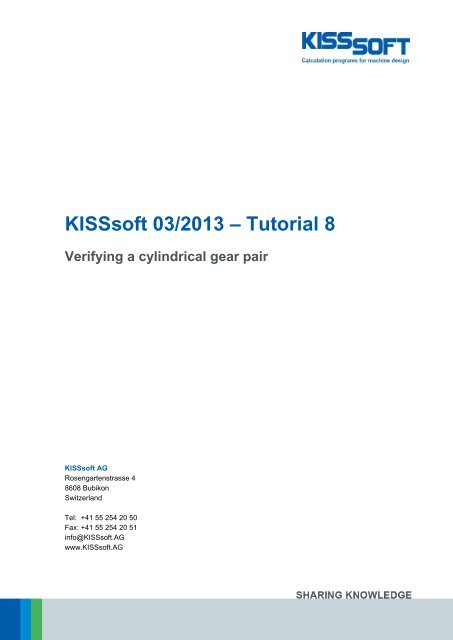
KISSs<strong>of</strong>t 03/2013 – Tutorial 8<br />
Verifying a cylindrical <strong>gear</strong> <strong>pair</strong><br />
KISSs<strong>of</strong>t <strong>AG</strong><br />
Rosengartenstrasse 4<br />
8608 Bubikon<br />
Switzerland<br />
Tel: +41 55 254 20 50<br />
Fax: +41 55 254 20 51<br />
info@KISSs<strong>of</strong>t.<strong>AG</strong><br />
www.KISSs<strong>of</strong>t.<strong>AG</strong>
Contents<br />
1 Task ......................................................................................................................................................... 3<br />
1.1 Input data ........................................................................................................................................ 3<br />
1.1.1 Power data ................................................................................................................................. 3<br />
1.1.2 Geometry .................................................................................................................................... 3<br />
1.1.3 Reference pr<strong>of</strong>ile ........................................................................................................................ 3<br />
1.1.4 Additional data ............................................................................................................................ 3<br />
2 Solution .................................................................................................................................................... 5<br />
2.1 Starting the s<strong>of</strong>tware ....................................................................................................................... 5<br />
2.2 Selecting a calculation .................................................................................................................... 5<br />
2.3 Gear Pair Geometry ....................................................................................................................... 6<br />
2.4 Defining the power data and calculation method ............................................................................ 7<br />
2.5 Material and lubrication .................................................................................................................. 9<br />
2.6 Reference pr<strong>of</strong>ile ............................................................................................................................ 9<br />
2.7 Tolerances .................................................................................................................................... 10<br />
2.8 Lubrication .................................................................................................................................... 11<br />
2.9 Calculate ....................................................................................................................................... 11<br />
2.10 Report ........................................................................................................................................... 13<br />
04.03.2013 2 / 21
1 Task<br />
This tutorial explains how to input data you already know for cylindrical <strong>gear</strong> <strong>pair</strong>s in the KISSs<strong>of</strong>t system.<br />
You must therefore perform the following steps for an existing cylindrical <strong>gear</strong> <strong>pair</strong>:<br />
Input the necessary data in KISSs<strong>of</strong>t<br />
Analyze it according to ISO 6336<br />
Document the results<br />
1.1 Input data<br />
The method you use to input the following data is described at the end <strong>of</strong> section 0 in this tutorial:<br />
1.1.1 Power data<br />
Power [P] 3.5 kW<br />
Speed [n] at drive 2500 1/min (Gear1 driving)<br />
Application factor [K A] 1.35<br />
Service life [H] 750 h<br />
1.1.2 Geometry<br />
Normal module [m n] 1.5 mm<br />
Helix angle at reference circle [ß] 25 °<br />
Pressure angle at normal section [ n] 20 °<br />
Number <strong>of</strong> teeth [z] Gear1/Gear2 16 / 43<br />
Face width [b] Gear1/Gear2 14 / 14.5 mm<br />
Center distance [a] 48.9 ±0.03 mm<br />
Pr<strong>of</strong>ile shift coefficient [x] Gear 1 (pinion) 0.3215<br />
1.1.3 Reference pr<strong>of</strong>ile<br />
Dedendum coefficient [h* FP] Root radius coefficient [* fP] Addendum coefficient [h* aP]<br />
Gear 1 (pinion) 1.25 0.3 1.0<br />
Gear 2 1.25 0.3 1.0<br />
1.1.4 Additional data<br />
Material:<br />
Material Hardness data Flim Hlim<br />
Gear 1 (pinion) 15 CrNi 6 case-hardened HRC 60 430 N/mm 2 1500 N/mm 2<br />
Gear 2 15 CrNi 6 case-hardened HRC 60 430 N/mm 2 1500 N/mm 2<br />
Lubrication:<br />
Grease lubrication Microlube GB 00 80 °C<br />
04.03.2013 3 / 21
Base tangent length allowances:<br />
No. <strong>of</strong> teeth spanned [k] Max. base tangent length<br />
[Wkmax]<br />
Gear 1 (pinion) 3 11.782 mm 11.758 mm<br />
Gear 2 6 25.214 mm 25.183 mm<br />
Min. base tangent length [Wkmin]<br />
Quality [Q] (DIN 6336) 8 / 8<br />
Tooth trace modification<br />
End relief<br />
Contact pattern<br />
not verified or inappropriate<br />
Type <strong>of</strong> pinion shaft<br />
Load case for the pinion shaft<br />
ISO 6336 Figure 13a;l = 53 mm; s = 5.9 mm; dsh = 14 mm<br />
04.03.2013 4 / 21
2 Solution<br />
2.1 Starting the s<strong>of</strong>tware<br />
You can call KISSs<strong>of</strong>t as soon as the s<strong>of</strong>tware has been installed and activated. Usually you start the<br />
program by clicking "StartProgram FilesKISSs<strong>of</strong>t 03-2013KISSs<strong>of</strong>t". This opens the following<br />
KISSs<strong>of</strong>t user interface:<br />
Figure 1.<br />
Starting KISSs<strong>of</strong>t, initial window<br />
2.2 Selecting a calculation<br />
In the Modules tree window, select the "Modules" tab to call the calculation for cylindrical <strong>gear</strong> <strong>pair</strong>s:<br />
Figure 2.<br />
Calling the cylindrical <strong>gear</strong> calculation<br />
04.03.2013 5 / 21
The KISSs<strong>of</strong>t input window then opens:<br />
Figure 3.<br />
KISSs<strong>of</strong>t Cylindrical <strong>gear</strong> calculation input window<br />
The following sections describe how to input parameters for the <strong>gear</strong> <strong>pair</strong>.<br />
2.3 Gear Pair Geometry<br />
Input the normal module (1.5 mm), pressure angle (20°), helix angle (25°), center distance (48.9 mm),<br />
number <strong>of</strong> teeth (16/43), tooth widths (14/14.5 mm), pr<strong>of</strong>ile shift coefficient (0.3215/...) and the quality (8/8)<br />
in the input window in the "Basic data" tab; "Geometry" group. You cannot input a value for the pr<strong>of</strong>ile shift<br />
<strong>of</strong> <strong>gear</strong> 2 directly because this value is calculated from the center distance and pr<strong>of</strong>ile shift <strong>of</strong> the first <strong>gear</strong>.<br />
However, you can click the Sizing button to size the value to match your requirements. You can set the<br />
quality to suit you, no matter which calculation method is in use.<br />
04.03.2013 6 / 21
Figure 4.<br />
Module-specific settings. Quality does not depend on calculation method.<br />
Figure 5.<br />
Input window – "Basic data" tab, "Geometry" group<br />
Click the Convert button to the right <strong>of</strong> the input fields to enter additional data for each field, or to input<br />
other data for these particular values. If you need to input an angle, right-click in the input field to open<br />
another window in which you can enter the angle, minutes and seconds:<br />
Figure 6.<br />
Additional entries, normal module, angle<br />
2.4 Defining the power data and calculation method<br />
Now, go to the input window in the "<strong>Rating</strong>" tab, group "Strength" and input the kinematics, the required<br />
service life (750 h) and the application factor (1.35). In this example, the torque is defined by inputting the<br />
power (3.5 kW) and speed (2500 1/min). However, in a different example, if you want to input the torque<br />
and calculate the power, simply set the "Selection" button to the right <strong>of</strong> the input field from torque to<br />
power. Under Details you can now input even more parameters about strength.<br />
It is also important that you set the reference <strong>gear</strong> correctly (first <strong>gear</strong> - <strong>gear</strong> 1) for the load.<br />
Input the calculation method in the drop-down list you see on the top left. In this case, you must also switch<br />
to ISO 6336 Method B.<br />
04.03.2013 7 / 21
Figure 7.<br />
Input window – "<strong>Rating</strong>" tab, group: Strength<br />
In the input window in the "Factors" tab, group “Face load factor/contact analysis”, you can input face load<br />
factor K Hß either directly (by using the drop down list “Own Input”) or define it by clicking the Plus button<br />
next to the input field.<br />
You must also select the Position <strong>of</strong> contact pattern, which is not verified, from the appropriate drop-down<br />
list.<br />
Figure 8.<br />
Define the face load factor<br />
To calculate the load coefficients, you must enter:<br />
The tooth trace modification (in this case Figure 8).<br />
Possible shaft configurations. To do this, click the Info button to the right <strong>of</strong> the "Type <strong>of</strong> pinion shaft"<br />
field in the "Info window". See the selection on the right-hand side <strong>of</strong> the next figure. This example<br />
corresponds to Figure A in Figure 9. You can then input the distances l and s as soon as the flag is set in<br />
the checkbox to the right <strong>of</strong> the corresponding input fields.<br />
Figure 9.<br />
Define face load factor<br />
Note:<br />
You need the shaft configuration to calculate face load factor K Hß . ISO 6336 (or DIN 3990) provides 5<br />
different configurations from which you can select the one you require. These examples are listed A to E in<br />
the figure at the top, on the right.<br />
04.03.2013 8 / 21
Face load factor K Hß shows the non-linear distribution <strong>of</strong> the load across the face width. You can request<br />
special instructions from KISSs<strong>of</strong>t <strong>AG</strong> about this: see document: "kisss<strong>of</strong>t-anl-072-E-Contact-Analysis-<br />
Cylindrical-Gears.pdf".<br />
2.5 Material and lubrication<br />
In the "Basic data" tab, "Material and lubrication" group input window you select the <strong>gear</strong> materials from a<br />
drop-down list. 15 Cr Ni 6, case-carburized steel is used in this example.<br />
You can also select the lubrication as well as the lubrication type.<br />
Input window – "Basic data" tab, "Material and Lubrication" group<br />
Click the Plus button<br />
on the far bottom right to define the lubricant temperature.<br />
2.6 Reference pr<strong>of</strong>ile<br />
In the "Reference pr<strong>of</strong>ile" tab you can now input further data, such as the reference pr<strong>of</strong>ile, the dedendum<br />
coefficient, the root radius factor and the addendum coefficient for Gear 1 and Gear 2.<br />
Figure 10.<br />
Input window – "Reference pr<strong>of</strong>ile" tab<br />
04.03.2013 9 / 21
2.7 Tolerances<br />
You define the tooth thickness deviation in the "Tolerances" tab. In a verification example, it is <strong>of</strong>ten the<br />
case that only the effective tolerances <strong>of</strong> base tangent length and the number <strong>of</strong> teeth spanned are<br />
specified. If you input these values, the KISSs<strong>of</strong>t system will then calculate the correct tooth thickness<br />
tolerances for the tooth form.<br />
In this case, you can also input the center distance tolerances either by selecting them from the drop-down<br />
list or by inputting your own values as shown in the example.<br />
Figure 11.<br />
Input window – "Tolerances" tab<br />
To input the base tangent lengths, click the "Tolerances" tab, "Deviation" group, and then click the Convert<br />
button<br />
next to the tooth thickness deviation input window (middle markings).<br />
Figure 12.<br />
Calculating the base tangent lengths<br />
You can now input the number <strong>of</strong> teeth spanned and the base tangent length (min/max). Then click<br />
Calculate. Then click "Accept" to transfer the values to the main screen.<br />
Attention: You cannot input a deviation until pr<strong>of</strong>ile shifts have been specified for both <strong>gear</strong>s. Otherwise you<br />
will receive incorrect values and you must repeat the sizing process.<br />
Note: You can change the number <strong>of</strong> teeth spanned between steps 2 and 3. To do this, set the flag in the<br />
checkbox next to the "Number <strong>of</strong> teeth spanned" field in the input window in the "Settings" group in the<br />
"Tolerances" tab and then change the Number <strong>of</strong> teeth spanned either in the "Settings" group or in the<br />
calculation screen.<br />
04.03.2013 10 / 21
Figure 13.<br />
Input window "Tolerances" tab, "Settings" group<br />
2.8 Lubrication<br />
The input window in the "Material and lubrication" group in the "Basic data" tab is only designed to hold the<br />
input value for lubricant temperature for the various types <strong>of</strong> lubricant that can be used. You can select<br />
other lubrication types and grease types in the appropriate drop-down list when you input the temperature<br />
as a numerical value.<br />
The "Lubricant temperature" input field for oil or grease lubrication defines the basic temperature <strong>of</strong> the<br />
<strong>gear</strong> body. For this reason, the "Lubricant temperature" is also important for calculating the effective<br />
lubricant viscosity. The "Ambient temperature" does not affect the calculation (see also 2.5 Material and<br />
lubrication).<br />
The "Ambient temperature" field only defines the base temperature during a dry run. In this case, the<br />
temperature <strong>of</strong> the <strong>gear</strong> body does influence the calculation.<br />
Exceptions:<br />
Worm <strong>gear</strong>s: the "Ambient temperature" is an input value used to calculate the temperature<br />
safety coefficient.<br />
Plastic <strong>gear</strong>s: as the strength values <strong>of</strong> plastic <strong>gear</strong>s depend greatly on the temperature <strong>of</strong> the <strong>gear</strong><br />
body you must input the corresponding temperatures here.<br />
Figure 14.<br />
Inputting the temperature for a dry run<br />
Figure 15.<br />
Inputting the temperature for grease lubrication<br />
2.9 Calculate<br />
Click in the tool bar or press "F5" to calculate the strength results. As the pro<strong>of</strong> <strong>of</strong> the contact pattern<br />
is missing, this message appears to tell you the K Hß value is too high.<br />
04.03.2013 11 / 21
Figure 16.<br />
Information window after "Calculation"<br />
This means that the calculation for the value K Hß was performed with an unrealistic contact pattern. When<br />
you test the contact pattern in the workshop, you can see whether this assumption was conservative or<br />
realistic.<br />
If you have worked through this tutorial correctly, the highlighted strength values should match Figure 18:<br />
Figure 17.<br />
End result <strong>of</strong> tutorial<br />
04.03.2013 12 / 21
2.10 Report<br />
KISSs<strong>of</strong>t Release 03/2013<br />
KISSs<strong>of</strong>t-Entwicklungs-Version KISSs<strong>of</strong>t <strong>AG</strong> CH-8608 BUBIKON<br />
File<br />
Name : Tutorial-008_ISO<br />
Description: KISSs<strong>of</strong>t example<br />
Changed by: ho am: 04.03.2013 um: 08:42:42<br />
Important hint: At least one warning has occurred during the calculation:<br />
1-> Indication:<br />
With the setting 'Position <strong>of</strong> the contact pattern: unfavorable'<br />
unrealistic high face load coefficient KHb is given for <strong>gear</strong>s with tooth trace modifications.<br />
CALCULATION OF A HELICAL GEAR PAIR<br />
Drawing or article number:<br />
Gear 1: 0.000.0<br />
Gear 2: 0.000.0<br />
Calculation method<br />
ISO 6336:2006 Method B<br />
------- GEAR 1 -------- GEAR 2 --<br />
Power (kW) [P] 3.500<br />
Speed (1/min) [n] 2500.0 930.2<br />
Torque (Nm) [T] 13.4 35.9<br />
Application factor [KA] 1.35<br />
Required service life [H] 750.00<br />
Gear driving (+) / driven (-) + -<br />
1. TOOTH GEOMETRY AND MATERIAL<br />
(geometry calculation according to<br />
DIN 3960:1987)<br />
------- GEAR 1 -------- GEAR 2 --<br />
Center distance (mm) [a] 48.900<br />
Centre distance allowances (mm) [Aa.e/i] 0.030 / -0.030<br />
Normal module (mm) [mn] 1.5000<br />
Pressure angle at normal section (°) [alfn] 20.0000<br />
Helix angle at reference circle (°) [beta] 25.0000<br />
Number <strong>of</strong> teeth [z] 16 43<br />
Facewidth (mm) [b] 14.00 14.50<br />
Hand <strong>of</strong> <strong>gear</strong> right left<br />
Accuracy grade [Q-ISO 1328:1995] 8 8<br />
Inner diameter (mm) [di] 0.00 0.00<br />
Inner diameter <strong>of</strong> <strong>gear</strong> rim (mm) [dbi] 0.00 0.00<br />
Material<br />
Gear 1:<br />
Gear 2:<br />
15 CrNi 6, Case-carburized steel, case-hardened<br />
ISO 6336-5 Figure 9/10 (MQ), core strength >=25HRC Jominy J=12mm=25HRC Jominy J=12mm
------- GEAR 1 -------- GEAR 2 --<br />
Surface hardness HRC 60 HRC 60<br />
Material quality according to ISO 6336:2006 Normal (Life factors ZNT and YNT >=0.85)<br />
Fatigue strength. tooth root stress (N/mm²) [sigFlim] 430.00 430.00<br />
Fatigue strength for Hertzian pressure (N/mm²) [sigHlim] 1500.00 1500.00<br />
Tensile strength (N/mm²) [Rm] 1000.00 1000.00<br />
Yield point (N/mm²) [Rp] 685.00 685.00<br />
Young's modulus (N/mm²) [E] 206000 206000<br />
Poisson's ratio [ny] 0.300 0.300<br />
Mean roughness, Ra, tooth flank (µm) [RAH] 0.60 0.60<br />
Mean roughness height, Rz, flank (µm) [RZH] 4.80 4.80<br />
Mean roughness height, Rz, root (µm) [RZF] 20.00 20.00<br />
Tool or reference pr<strong>of</strong>ile <strong>of</strong> <strong>gear</strong> 1 :<br />
Reference pr<strong>of</strong>ile 1.25 / 0.30 / 1.0 ISO 53.2:1997 Pr<strong>of</strong>il B<br />
Dedendum coefficient [hfP*] 1.250<br />
Root radius factor [rh<strong>of</strong>P*] 0.300<br />
Addendum coefficient [haP*] 1.000<br />
Tip radius factor [rhoaP*] 0.000<br />
Tip form height coefficient [hFaP*] 0.000<br />
Protuberance height factor [hprP*] 0.000<br />
Protuberance angle [alfprP] 0.000<br />
Ramp angle [alfKP] 0.000<br />
not topping<br />
Tool or reference pr<strong>of</strong>ile <strong>of</strong> <strong>gear</strong> 2 :<br />
Reference pr<strong>of</strong>ile 1.25 / 0.30 / 1.0 ISO 53.2:1997 Pr<strong>of</strong>il B<br />
Dedendum coefficient [hfP*] 1.250<br />
Root radius factor [rh<strong>of</strong>P*] 0.300<br />
Addendum coefficient [haP*] 1.000<br />
Tip radius factor [rhoaP*] 0.000<br />
Tip form height coefficient [hFaP*] 0.000<br />
Protuberance height factor [hprP*] 0.000<br />
Protuberance angle [alfprP] 0.000<br />
Ramp angle [alfKP] 0.000<br />
not topping<br />
Summary <strong>of</strong> reference pr<strong>of</strong>ile <strong>gear</strong>s:<br />
Dedendum reference pr<strong>of</strong>ile (in module) [hfP*] 1.250 1.250<br />
Root radius reference pr<strong>of</strong>ile (in module) [r<strong>of</strong>P*] 0.300 0.300<br />
Addendum reference pr<strong>of</strong>ile (in module) [haP*] 1.000 1.000<br />
Protuberance height coefficient (in module) [hprP*] 0.000 0.000<br />
Protuberance angle (°) [alfprP] 0.000 0.000<br />
Tip form height coefficient (in module) [hFaP*] 0.000 0.000<br />
Ramp angle (°) [alfKP] 0.000 0.000<br />
Type <strong>of</strong> pr<strong>of</strong>ile modification:<br />
none (only running-in)<br />
Tip relief (µm) [Ca] 2.0 2.0<br />
Lubrication type<br />
Grease lubrication<br />
Type <strong>of</strong> grease Grease: Microlube GB 00<br />
Lubricant base<br />
Mineral-oil base<br />
Kinem. viscosity base oil at 40 °C (mm²/s) [nu40] 700.00<br />
Kinem. viscosity base oil at 100 °C (mm²/s) [nu100] 35.00<br />
FZG-Test A/8.3/90 step [FZGtestA] 12<br />
Specific density at 15 °C (kg/dm³) [roOil] 0.900<br />
04.03.2013 14 / 21
Grease temperature (°C) [TS] 80.000<br />
------- GEAR 1 -------- GEAR 2 --<br />
Overall transmission ratio [itot] -2.688<br />
Gear ratio [u] 2.688<br />
Transverse module (mm) [mt] 1.655<br />
Pressure angle at pitch circle (°) [alft] 21.880<br />
Working transverse pressure angle (°) [alfwt] 22.100<br />
[alfwt.e/i] 22.186 / 22.013<br />
Working pressure angle at normal section (°) [alfwn] 20.199<br />
Helix angle at operating pitch circle (°) [betaw] 25.034<br />
Base helix angle (°) [betab] 23.399<br />
Reference centre distance (mm) [ad] 48.824<br />
Sum <strong>of</strong> pr<strong>of</strong>ile shift coefficients [Summexi] 0.0506<br />
Pr<strong>of</strong>ile shift coefficient [x] 0.3215 -0.2709<br />
Tooth thickness (Arc) (module) (module) [sn*] 1.8048 1.3736<br />
Tip alteration (mm) [k*mn] 0.000 0.000<br />
Reference diameter (mm) [d] 26.481 71.168<br />
Base diameter (mm) [db] 24.573 66.041<br />
Tip diameter (mm) [da] 30.446 73.355<br />
(mm) [da.e/i] 30.446 / 30.436 73.355 / 73.345<br />
Tip diameter allowances (mm) [Ada.e/i] 0.000 / -0.010 0.000 / -0.010<br />
Tip form diameter (mm) [dFa] 30.446 73.355<br />
(mm) [dFa.e/i] 30.446 / 30.436 73.355 / 73.345<br />
Active tip diameter (mm) [dNa.e/i] 30.446 / 30.436 73.355 / 73.345<br />
Operating pitch diameter (mm) [dw] 26.522 71.278<br />
(mm) [dw.e/i] 26.538 / 26.506 71.322 / 71.234<br />
Root diameter (mm) [df] 23.696 66.605<br />
Generating Pr<strong>of</strong>ile shift coefficient [xE.e/i] 0.2601/ 0.2367 -0.3275/ -0.3577<br />
Manufactured root diameter with xE (mm) [df.e/i] 23.511 / 23.441 66.436 / 66.345<br />
Theoretical tip clearance (mm) [c] 0.375 0.375<br />
Effective tip clearance (mm) [c.e/i] 0.540 / 0.429 0.537 / 0.437<br />
Active root diameter (mm) [dNf] 25.050 68.670<br />
(mm) [dNf.e/i] 25.086 / 25.020 68.719 / 68.627<br />
Root form diameter (mm) [dFf] 24.894 67.921<br />
(mm) [dFf.e/i] 24.820 / 24.794 67.816 / 67.761<br />
Reserve (dNf-dFf)/2 (mm) [cF.e/i] 0.146 / 0.100 0.479 / 0.405<br />
Addendum (mm) [ha=mn*(haP*+x)] 1.982 1.094<br />
(mm) [ha.e/i] 1.982 / 1.977 1.094 / 1.089<br />
Dedendum (mm) [hf=mn*(hfP*-x)] 1.393 2.281<br />
(mm) [hf.e/i] 1.485 / 1.520 2.366 / 2.411<br />
Roll angle at dFa (°) [xsi_dFa.e/i] 41.909 / 41.870 27.702 / 27.682<br />
Roll angle to dNa (°) [xsi_dNa.e/i] 41.909 / 41.870 27.702 / 27.682<br />
Roll angle to dNf (°) [xsi_dNf.e/i] 11.766 / 10.969 16.480 / 16.189<br />
Roll angle at dFf (°) [xsi_dFf.e/i] 8.135 / 7.696 13.371 / 13.160<br />
Tooth height (mm) [H] 3.375 3.375<br />
Virtual <strong>gear</strong> no. <strong>of</strong> teeth [zn] 20.960 56.329<br />
Normal tooth thickness at tip cyl. (mm) [san] 0.874 1.225<br />
(mm) [san.e/i] 0.806 / 0.771 1.166 / 1.127<br />
Normal spacewidth at root cylinder (mm) [efn] 0.000 1.352<br />
(mm) [efn.e/i] 0.000 / 0.000 1.388 / 1.409<br />
Max. sliding velocity at tip (m/s) [vga] 1.436 0.919<br />
Specific sliding at the tip [zetaa] 0.610 0.591<br />
Specific sliding at the root [zetaf] -1.443 -1.567<br />
Sliding factor on tip [Kga] 0.414 0.265<br />
Sliding factor on root [Kgf] -0.265 -0.414<br />
Pitch on reference circle (mm) [pt] 5.200<br />
04.03.2013 15 / 21
Base pitch (mm) [pbt] 4.825<br />
Transverse pitch on contact-path (mm) [pet] 4.825<br />
Lead height (mm) [pz] 178.408 479.470<br />
Axial pitch (mm) [px] 11.150<br />
Length <strong>of</strong> path <strong>of</strong> contact (mm) [ga, e/i] 6.555 ( 6.635 / 6.456)<br />
Length T1-A, T2-A (mm) [T1A, T2A] 2.432( 2.352/ 2.523) 15.965( 15.965/ 15.954)<br />
Length T1-B (mm) [T1B, T2B] 4.162( 4.162/ 4.154) 14.235( 14.155/ 14.323)<br />
Length T1-C (mm) [T1C, T2C] 4.989( 4.967/ 5.011) 13.408( 13.350/ 13.466)<br />
Length T1-D (mm) [T1D, T2D] 7.257( 7.177/ 7.348) 11.140( 11.140/ 11.129)<br />
Length T1-E (mm) [T1E, T2E] 8.987( 8.987/ 8.979) 9.410( 9.330/ 9.498)<br />
Length T1-T2 (mm) [T1T2] 18.397 ( 18.317 / 18.477)<br />
Diameter <strong>of</strong> single contact point B (mm) [d-B] 25.945( 25.945/ 25.940) 71.916( 71.853/ 71.986)<br />
Diameter <strong>of</strong> single contact point D (mm) [d-D] 28.540( 28.459/ 28.633) 69.698( 69.698/ 69.691)<br />
Addendum contact ratio [eps] 0.829( 0.833/ 0.822) 0.530( 0.542/ 0.516)<br />
Minimal length <strong>of</strong> contact line (mm) [Lmin] 19.611<br />
Transverse contact ratio [eps_a] 1.359<br />
Transverse contact ratio with allowances [eps_a.e/m/i] 1.375 / 1.357 / 1.338<br />
Overlap ratio [eps_b] 1.256<br />
Total contact ratio [eps_g] 2.614<br />
Total contact ratio with allowances [eps_g.e/m/i] 2.631 / 2.612 / 2.594<br />
2. FACTORS OF GENERAL INFLUENCE<br />
------- GEAR 1 -------- GEAR 2 --<br />
Nominal circum. force at pitch circle (N) [Ft] 1009.7<br />
Axial force (N) [Fa] 470.8<br />
Radial force (N) [Fr] 405.5<br />
Normal force (N) [Fnorm] 1185.6<br />
Tangent.load at p.c.d.per mm (N/mm) (N/mm) [w] 72.12<br />
Only as information: Forces at operating pitch circle:<br />
Nominal circumferential force (N) [Ftw] 1008.1<br />
Axial force (N) [Faw] 470.8<br />
Radial force (N) [Frw] 409.4<br />
Circumferential speed pitch d.. (m/sec) [v] 3.47<br />
Running-in value (µm) [yp] 1.0<br />
Running-in value (µm) [yf] 1.0<br />
Correction coefficient [CM] 0.800<br />
Gear body coefficient [CR] 1.000<br />
Reference pr<strong>of</strong>ile coefficient [CBS] 0.975<br />
Material coefficient [E/Est] 1.000<br />
Singular tooth stiffness (N/mm/µm) [c'] 12.156<br />
Meshing stiffness (N/mm/µm) [cgalf] 15.426<br />
Meshing stiffness (N/mm/µm) [cgbet] 13.112<br />
Reduced mass (kg/mm) [mRed] 0.00235<br />
Resonance speed (min-1) [nE1] 48315<br />
Nominal speed (-) [N] 0.052<br />
Subcritical range<br />
Running-in value (µm) [ya] 1.0<br />
Bearing distance l <strong>of</strong> pinion shaft (mm) [l] 53.000<br />
Distance s <strong>of</strong> pinion shaft (mm) [s] 5.900<br />
Outside diameter <strong>of</strong> pinion shaft (mm) [dsh] 14.000<br />
Load according to Figure 16, ISO 6336-1:2006 [-] 0<br />
0:a), 1:b), 2:c), 3:d), 4:e)<br />
Coefficient K' according to Figure 13,<br />
ISO 6336-1:2006 [K'] 0.80<br />
04.03.2013 16 / 21
Without support effect<br />
Tooth trace deviation (active) (µm) [Fby] 15.10<br />
from deformation <strong>of</strong> shaft (µm) [fsh*B1] 2.56<br />
Tooth trace: with end relief<br />
Position <strong>of</strong> Contact pattern: not verified or inappropriate<br />
from production tolerances (µm) [fma*B2] 14.36<br />
Tooth trace deviation, theoretical (µm) [Fbx] 17.77<br />
Running-in value (µm) [yb] 2.67<br />
Dynamic factor [KV] 1.050<br />
Face load factor - flank [KHb] 1.968<br />
- Tooth root [KFb] 1.676<br />
- Scuffing [KBb] 1.968<br />
Transverse load factor - flank [KHa] 1.338<br />
- Tooth root [KFa] 1.338<br />
- Scuffing [KBa] 1.338<br />
Helical load factor scuffing [Kbg] 1.242<br />
Number <strong>of</strong> load cycles (in mio.) [NL] 112.500 41.860<br />
IF (@UNKNOWN DATADICT)<br />
IF (@UNKNOWN DATADICT)<br />
3. TOOTH ROOT STRENGTH<br />
Calculation <strong>of</strong> Tooth form coefficients according method: B<br />
Tooth form factors calculated with manufacturing pr<strong>of</strong>ile shift xE.e<br />
------- GEAR 1 -------- GEAR 2 --<br />
Tooth form factor [YF] 1.37 1.67<br />
Stress correction factor [YS] 2.15 1.84<br />
Working angle (°) [alfFen] 21.64 18.97<br />
Bending lever arm (mm) [hF] 1.52 1.84<br />
Tooth thickness at root (mm) [sFn] 3.14 3.15<br />
Tooth root radius (mm) [roF] 0.65 0.82<br />
(hF* = 1.012/ 1.225 sFn* = 2.093/ 2.102 roF* = 0.431/ 0.545 dsFn = 24.00/ 67.03 alfsFn = 30.00/ 30.00)<br />
Contact ratio factor [Yeps] 1.000<br />
Helical load factor [Ybet] 0.792<br />
Deep tooth factor [YDT] 1.000<br />
Gear rim factor [YB] 1.000 1.000<br />
Effective facewidth (mm) [beff] 14.00 14.50<br />
Nominal stress at tooth root (N/mm²) [sigF0] 112.30 113.33<br />
Tooth root stress (N/mm²) [sigF] 357.19 360.47<br />
Permissible bending stress at root <strong>of</strong> Test-<strong>gear</strong><br />
Support factor [YdrelT] 0.999 0.994<br />
Surface factor [YRrelT] 0.957 0.957<br />
Size coefficient (Tooth root) [YX] 1.000 1.000<br />
Finite life factor [YNT] 0.930 0.949<br />
[YdrelT*YRrelT*YX*YNT] 0.889 0.902<br />
Alternating bending coefficient [YM] 1.000 1.000<br />
Stress correction factor [Yst] 2.00<br />
Yst*sigFlim (N/mm²) [sigFE] 860.00 860.00<br />
Limit strength tooth root [sigFG] 764.63 776.06<br />
Permissible tooth root stress (N/mm²) [sigFP=sigFG/SFmin] 588.17 596.97<br />
04.03.2013 17 / 21
Required safety [SFmin] 1.30 1.30<br />
Safety for Tooth root stress [SF=sigFG/sigF] 2.14 2.15<br />
Transmittable power (kW) [kW<strong>Rating</strong>] 5.76 5.80<br />
4. SAFETY <strong>AG</strong>AINST PITTING (TOOTH FLANK)<br />
------- GEAR 1 -------- GEAR 2 --<br />
Zone factor [ZH] 2.291<br />
Elasticity coefficient (N^.5/mm) [ZE] 189.812<br />
Contact ratio factor [Zeps] 0.858<br />
Helix angle factor [Zbet] 1.050<br />
Effective facewidth (mm) [beff] 14.00<br />
Nominal flank pressure (N/mm²) [sigH0] 757.63<br />
Surface pressure at operating pitch circle (N/mm²)<br />
[sigHw] 1464.09<br />
Single tooth contact factor [ZB,ZD] 1.00 1.00<br />
Flank pressure (N/mm²) [sigH] 1464.09 1464.09<br />
Lubrication coefficient at NL [ZL] 1.096 1.093<br />
Speed coefficient at NL [ZV] 0.974 0.975<br />
Roughness coefficient at NL [ZR] 0.937 0.939<br />
Material <strong>pair</strong>ing coefficient at NL [ZW] 1.000 1.000<br />
Finite life factor [ZNT] 0.975 1.014<br />
[ZL*ZV*ZR*ZNT] 0.976 1.014<br />
Small amount <strong>of</strong> pitting permissible (0=no, 1=yes) 0 0<br />
Size coefficient (flank) [ZX] 1.000 1.000<br />
Limit strength pitting (N/mm²) [sigHG] 1464.48 1521.64<br />
Permissible surface pressure (N/mm²) [sigHP=sigHG/SHmin] 1541.56 1601.73<br />
Safety for surface pressure at operating pitch circle<br />
[SHw] 1.00 1.04<br />
Required safety [SHmin] 0.95 0.95<br />
Transmittable power (kW) [kW<strong>Rating</strong>] 3.88 4.19<br />
Safety for stress at single tooth contact [SHBD=sigHG/sigH] 1.00 1.04<br />
(Safety regarding nominal torque) [(SHBD)^2] 1.00 1.08<br />
4b. MICROPITTING ACCORDING TO ISO TR 15144-1:2010<br />
Calculation did not run. (Lubricant: Load stage micropitting test is unknown.)<br />
5. STRENGTH <strong>AG</strong>AINST SCUFFING<br />
Calculation method according to<br />
ISO TR 13989:2000<br />
The calculation <strong>of</strong> load capacity for scuffing does not cover grease.<br />
The FZG-Test stage<br />
estimated for grease.<br />
The calculation can only serve as a rough guide.!<br />
[FZGtestA] is only<br />
Lubrication coefficient (for lubrication type) [XS] 1.200<br />
Multiple meshing factor [Xmp] 1.000<br />
Relative structure coefficient (Scuffing) [XWrelT] 1.000<br />
04.03.2013 18 / 21
Thermal contact factor (N/mm/s^.5/K) [BM] 13.780 13.780<br />
Relevant tip relief (µm) [Ca] 2.00 2.00<br />
Optimal tip relief (µm) [Ceff] 6.31<br />
Effective facewidth (mm) [beff] 14.000<br />
Applicable circumferential force/facewidth (N/mm)<br />
[wBt] 269.330<br />
(Kbg = 1.242, wBt*Kbg = 334.533)<br />
Pressure angle factor (eps1:<br />
0.829, eps2: 0.530) [Xalfbet] 0.990<br />
Flash temperature-criteria<br />
Lubricant factor [XL] 0.812<br />
Tooth mass temperature (°C) [theMi] 93.82<br />
theM = theoil + XS*0.47*Xmp*theflm [theflm] 24.50<br />
Scuffing temperature (°C) [theS] 343.17<br />
Coordinate gamma (point <strong>of</strong> highest temp.) [Gamma] 0.788<br />
[Gamma.A]=-0.513 [Gamma.E]= 0.801<br />
Highest contact temp. (°C) [theB] 154.03<br />
Flash factor (°K*N^-.75*s^.5*m^-.5*mm) [XM] 50.058<br />
Approach factor [XJ] 1.000<br />
Load sharing factor [XGam] 0.920<br />
Dynamic viscosity (mPa*s) [etaM] 64.01 ( 80.0 °C)<br />
Coefficient <strong>of</strong> friction [mym] 0.074<br />
Required safety [SBmin] 2.000<br />
Safety factor for scuffing (flash-temp) [SB] 3.555<br />
Integral temperature-criteria<br />
Lubricant factor [XL] 1.000<br />
Tooth mass temperature (°C) [theM-C] 98.75<br />
theM-C = theoil + XS*0.70*theflaint [theflaint] 22.32<br />
Integral scuffing temperature (°C) [theSint] 357.16<br />
Flash factor (°K*N^-.75*s^.5*m^-.5*mm) [XM] 50.058<br />
Running-in factor (well run in) [XE] 1.000<br />
Contact ratio factor [Xeps] 0.282<br />
Dynamic viscosity (mPa*s) [etaOil] 64.01 ( 80.0 °C)<br />
Averaged coefficient <strong>of</strong> friction [mym] 0.101<br />
Geometry factor [XBE] 0.364<br />
Meshing factor [XQ] 1.000<br />
Tip relief factor [XCa] 1.261<br />
Integral tooth flank temperature (°C) [theint] 132.24<br />
Required safety [SSmin] 1.800<br />
Safety factor for scuffing (intg.-temp.) [SSint] 2.701<br />
Safety referring to transferred torque [SSL] 5.306<br />
6. MEASUREMENTS FOR TOOTH THICKNESS<br />
------- GEAR 1 -------- GEAR 2 --<br />
Tooth thickness deviation Own Input Own Input<br />
Tooth thickness allowance (normal section) (mm) [As.e/i] -0.067 / -0.093 -0.062 / -0.095<br />
Number <strong>of</strong> teeth spanned [k] 3.000 6.000<br />
Base tangent length (no backlash) (mm) [Wk] 11.845 25.272<br />
Actual base tangent length ('span') (mm) [Wk.e/i] 11.782 / 11.758 25.214 / 25.183<br />
Diameter <strong>of</strong> contact point (mm) [dMWk.m] 26.843 69.973<br />
Theoretical diameter <strong>of</strong> ball/pin (mm) [DM] 2.789 2.496<br />
Eff. Diameter <strong>of</strong> ball/pin (mm) [DMeff] 3.000 2.500<br />
04.03.2013 19 / 21
Theor. dim. centre to ball (mm) [MrK] 16.053 36.846<br />
Actual dimension centre to ball (mm) [MrK.e/i] 15.989 / 15.964 36.760 / 36.714<br />
Diameter <strong>of</strong> contact point (mm) [dMMr.m] 27.596 70.166<br />
Diametral measurement over two balls without clearance (mm)<br />
[MdK] 32.107 73.644<br />
Actual dimension over balls (mm) [MdK.e/i] 31.978 / 31.929 73.473 / 73.381<br />
Diametral measurement over rolls without clearance (mm)<br />
[MdR] 32.107 73.691<br />
Actual dimension over rolls (mm) [MdR.e/i] 31.978 / 31.929 73.520 / 73.428<br />
Dimensions over 3 rolls without clearance (mm) [Md3R] 0.000 73.691<br />
Actual dimensions over 3 rolls (mm) [Md3R.e/i] 0.000 / 0.000 73.520 / 73.428<br />
Chordal tooth thickness (no backlash) (mm) ['sn] 2.704 2.060<br />
Actual chordal tooth thickness (mm) ['sn.e/i] 2.637 / 2.611 1.998 / 1.965<br />
Reference chordal height from da.m (mm) [ha] 2.037 1.103<br />
Tooth thickness (Arc) (mm) [sn] 2.707 2.060<br />
(mm) [sn.e/i] 2.640 / 2.615 1.999 / 1.966<br />
Backlash free center distance (mm) [aControl.e/i] 48.723 / 48.641<br />
Backlash free center distance, allowances (mm) [jta] -0.177 / -0.259<br />
dNf.i with aControl (mm) [dNf0.i] 24.816 68.300<br />
Reserve (dNf0.i-dFf.e)/2 (mm) [cF0.i] -0.002 0.242<br />
Centre distance allowances (mm) [Aa.e/i] 0.030 / -0.030<br />
Circumferential backlash from Aa (mm) [jt_Aa.e/i] 0.024 / -0.024<br />
Radial clearance (mm) [jr] 0.289 / 0.147<br />
Circumferential backlash (transverse section) (mm)<br />
[jt] 0.231 / 0.118<br />
Torsional angle for fixed <strong>gear</strong> 1 (°) 0.3725 / 0.1899<br />
Normal backlash (mm) [jn] 0.197 / 0.100<br />
7. GEAR ACCURACY<br />
------- GEAR 1 -------- GEAR 2 --<br />
According to ISO 1328:1995:<br />
Accuracy grade [Q-ISO1328] 8 8<br />
Single pitch deviation (µm) [fpt] 14.00 15.00<br />
Base circle pitch deviation (µm) [fpb] 13.00 13.90<br />
Cumulative circular pitch deviation over k/8 pitches (µm)<br />
[Fpk/8] 19.00 24.00<br />
Pr<strong>of</strong>ile form deviation (µm) [ffa] 11.00 13.00<br />
Pr<strong>of</strong>ile slope deviation (µm) [fHa] 9.50 11.00<br />
Total pr<strong>of</strong>ile deviation (µm) [Fa] 15.00 17.00<br />
Helix form deviation (µm) [ffb] 14.00 15.00<br />
Helix slope deviation (µm) [fHb] 14.00 15.00<br />
Total helix deviation (µm) [Fb] 20.00 21.00<br />
Total cumulative pitch deviation (µm) [Fp] 41.00 52.00<br />
Concentricity deviation (µm) [Fr] 32.00 42.00<br />
Total radial composite deviation (µm) [Fi"] 45.00 55.00<br />
Radial tooth-to-tooth composite deviation (µm) [fi"] 13.00 13.00<br />
Total tangential composite deviation (µm) [Fi'] 61.00 74.00<br />
Tangential tooth-to-tooth composite deviation (µm)<br />
[fi'] 21.00 22.00<br />
Axis alignment tolerances (recommendation acc. ISO TR 10064:1992, Quality 8)<br />
Maximum value for deviation error <strong>of</strong> axis (µm) [fSigbet] 39.75 (Fb= 21.00)<br />
Maximum value for inclination error <strong>of</strong> axes (µm) [fSigdel] 79.50<br />
04.03.2013 20 / 21
8. ADDITIONAL DATA<br />
Maximal possible centre distance (eps_a=1.0) [aMAX] 49.577<br />
Torsional stiffness (MNm/rad) [cr] 0.0 0.2<br />
Mean coeff. <strong>of</strong> friction (acc. Niemann) [mum] 0.098<br />
Wear sliding coef. by Niemann [zetw] 0.819<br />
Power loss from <strong>gear</strong> load (kW) [PVZ] 0.061<br />
(Meshing efficiency (%) [etaz] 98.254)<br />
Weight - calculated with da (g) [Mass] 79.80 479.82<br />
Total weight (g) [Mass] 559.63<br />
Moment <strong>of</strong> inertia (System referenced to wheel 1):<br />
Calculation taking into account the exact tooth-shape<br />
single <strong>gear</strong>s (da...di) (kg*m²) [TraeghMom] 5.984e-006 0.000269<br />
System (da...df) (kg*m²) [TraeghMomDaDf] 9.971e-006<br />
System (da...di) (kg*m²) [TraeghMom] 4.322e-005<br />
Indications for the manufacturing by wire cutting:<br />
Deviation from theoretical tooth trace (µm) [WireErr] 400.3 149.6<br />
Permissible deviation (µm) [Fb/2] 10.0 10.5<br />
9. DETERMINATION OF TOOTHFORM<br />
Data for the tooth form calculation :<br />
Calculation <strong>of</strong> Gear 1<br />
Tooth form, Gear 1, Step 1: automatic (final treatment)<br />
haP*= 1.071, hfP*= 1.250, r<strong>of</strong>P*= 0.300<br />
Calculation <strong>of</strong> Gear 2<br />
Tooth form, Gear 2, Step 1: automatic (final treatment)<br />
haP*= 1.070, hfP*= 1.250, r<strong>of</strong>P*= 0.300<br />
REMARKS:<br />
- Specifications with [.e/i] imply: Maximum [e] and Minimal value [i] with<br />
consideration <strong>of</strong> all tolerances<br />
Specifications with<br />
[.m] imply: Mean value within tolerance<br />
- For the backlash tolerance, the center distance tolerances and the tooth thickness<br />
deviation are taken into account. Shown is the maximal and the minimal backlash corresponding<br />
the largest resp. the smallest allowances<br />
The calculation is done for the Operating pitch circle..<br />
- Calculation <strong>of</strong> Zbet according Corrigendum 1 ISO 6336-2:2008 with Zbet = 1/(COS(beta)^0.5)<br />
- Details <strong>of</strong> calculation method:<br />
cg according to method B<br />
KV according to method B<br />
KHb, KFb according method C<br />
fma following equation (64), fsh following (57/58), Fbx following (52/53/57)<br />
KHa, KFa according to method B<br />
End <strong>of</strong> Report lines: 502<br />
04.03.2013 21 / 21