Shanks Owners manual (10 Build) 30, 30H, 35, 35H, 40 ... - EP Barrus
Shanks Owners manual (10 Build) 30, 30H, 35, 35H, 40 ... - EP Barrus
Shanks Owners manual (10 Build) 30, 30H, 35, 35H, 40 ... - EP Barrus

You also want an ePaper? Increase the reach of your titles
YUMPU automatically turns print PDFs into web optimized ePapers that Google loves.
SHANKS CANAL BOAT ENGINE MANUAL<br />
For The Following Engine Models:<br />
SHANKS <strong>10</strong> <strong>30</strong><br />
SHANKS <strong>10</strong> <strong>30</strong>H<br />
SHANKS <strong>10</strong> <strong>35</strong><br />
SHANKS <strong>10</strong> <strong>35</strong>H<br />
SHANKS <strong>10</strong> <strong>40</strong><br />
SHANKS <strong>10</strong> 45<br />
Model<br />
Iss<br />
Serial No<br />
072000<br />
Enter your engine identification details in the spaces provided above.<br />
RDG6039484 <strong>Shanks</strong> <strong>10</strong> <strong>Owners</strong> Manual Issue 1
Index<br />
SECTION 1 - Safety Precautions ....................................................................................... 6<br />
1. General............................................................................................................................................. 6<br />
2. Lifting................................................................................................................................................ 6<br />
3. Rotating Shafts and Belts................................................................................................................. 6<br />
4. Exhaust System ............................................................................................................................... 6<br />
5. Launching and Lifting Boats............................................................................................................. 6<br />
6. Batteries ........................................................................................................................................... 7<br />
SECTION 2 - Engine Identification..................................................................................... 8<br />
SECTION 3 - Installation..................................................................................................... 9<br />
1. Ventilation......................................................................................................................................... 9<br />
2. Engine Beds ..................................................................................................................................... 9<br />
3. Cooling System ................................................................................................................................ 9<br />
4. Skin Tanks........................................................................................................................................ 9<br />
5. Pressurised Water Header Tank.................................................................................................... <strong>10</strong><br />
6. Shaft Connection and Propeller Selection ..................................................................................... <strong>10</strong><br />
7. Engine Anti-Vibration Mounts......................................................................................................... <strong>10</strong><br />
8. Engine Mount Installation............................................................................................................... 11<br />
9. Engine Alignment ........................................................................................................................... 13<br />
<strong>10</strong>. Electrics.......................................................................................................................................... 13<br />
11. Engine Oil....................................................................................................................................... 14<br />
12. Fuel................................................................................................................................................. 14<br />
13. Coolant ........................................................................................................................................... 15<br />
14. Calorifier ......................................................................................................................................... 17<br />
15. Control Cables................................................................................................................................ 17<br />
16. Domestic Battery Bank................................................................................................................... 17<br />
17. Control Panel.................................................................................................................................. 17<br />
SECTION 4 - Operation..................................................................................................... 18<br />
1. Starting the Engine for the First Time ............................................................................................ 18<br />
2. Starting Procedure ......................................................................................................................... 18<br />
3. Stopping Procedure........................................................................................................................ 19<br />
4. Full Load Running .......................................................................................................................... 19<br />
5. Refuelling ....................................................................................................................................... 19<br />
6. Diesel Fuel Additive........................................................................................................................ 19<br />
7. Twin Thermostats........................................................................................................................... 20<br />
8. Exhaust Back Pressure.................................................................................................................. 20<br />
SECTION 5 - Service Procedure ...................................................................................... 22<br />
1. Engine Oil and Filter Change ......................................................................................................... 22<br />
2. Air Filter Check & Change.............................................................................................................. 22<br />
3. Gearbox Oil Change....................................................................................................................... 23<br />
4. Primary Fuel Filter Water Drain...................................................................................................... 25<br />
RDG6039484 <strong>Shanks</strong><strong>10</strong> <strong>Owners</strong> Manual Issue 1 Page 2 of 51
5. Primary Fuel Filter Change ............................................................................................................ 25<br />
6. Secondary Fuel Filter Change ....................................................................................................... 26<br />
7. Bleeding the Fuel System. ............................................................................................................. 26<br />
8. Cooling System .............................................................................................................................. 27<br />
9. Belt Adjustment .............................................................................................................................. 28<br />
<strong>10</strong>. Belt Maintenance............................................................................................................................ 28<br />
11. Belt Replacement ........................................................................................................................... 28<br />
12. Standard Panel Maintenance......................................................................................................... 29<br />
13. Deluxe Panel Maintenance (if fitted) .............................................................................................. 29<br />
14. Checking Injection Pump Oil .......................................................................................................... <strong>30</strong><br />
15. Gearbox Hydraulic Oil Filter (<strong>Shanks</strong> <strong>30</strong>H, <strong>35</strong>H, <strong>40</strong> and 45) ......................................................... 31<br />
16. Valve Clearance Adjustment.......................................................................................................... 32<br />
17. Oil Recovery Filter.......................................................................................................................... 34<br />
SECTION 6 - Service Schedule ........................................................................................ <strong>35</strong><br />
Specifications and Capacities .................................................................................................................. <strong>35</strong><br />
Service Intervals....................................................................................................................................... 36<br />
SECTION 7 - <strong>Shanks</strong> Engine Specification..................................................................... 37<br />
Cylinder Head Tightening Pattern ............................................................................................................ 38<br />
SECTION 8 - Wiring Diagrams ......................................................................................... 39<br />
Harness Wiring Diagram .......................................................................................................................... 39<br />
Panel Wiring Diagram .............................................................................................................................. 41<br />
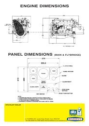
SECTION 9 - General Arrangements ............................................................................... 43<br />
<strong>Shanks</strong><strong>10</strong> <strong>30</strong>............................................................................................................................................. 43<br />
<strong>Shanks</strong><strong>10</strong> <strong>30</strong>H.......................................................................................................................................... 44<br />
<strong>Shanks</strong><strong>10</strong> <strong>35</strong>............................................................................................................................................. 45<br />
<strong>Shanks</strong><strong>10</strong> <strong>35</strong>H.......................................................................................................................................... 46<br />
<strong>Shanks</strong><strong>10</strong> <strong>40</strong>............................................................................................................................................. 47<br />
<strong>Shanks</strong><strong>10</strong> 45............................................................................................................................................. 48<br />
SECTION <strong>10</strong> - Dealer List ................................................................................................. 50<br />
SECTION 11 - <strong>Shanks</strong> Service Parts ............................................................................... 51<br />
RDG6039484 <strong>Shanks</strong><strong>10</strong> <strong>Owners</strong> Manual Issue 1 Page 3 of 51
Declaration of Conformity for Recreational Craft Propulsion Engine<br />
with the requirements of Directive 94/25/EC as amended by<br />
2003/44/EC.<br />
Name of Engine Manufacturer: E.P.<strong>Barrus</strong> Ltd<br />
Address: E.P.<strong>Barrus</strong> Ltd, Launton Road, Bicester, Oxon, OX26 4UR, England<br />
Name of Authorised Representative: E.P.<strong>Barrus</strong> Ltd<br />
Address: E.P.<strong>Barrus</strong> Ltd, Launton Road, Bicester, Oxon, OX26 4UR, England<br />
Engine type approved according to: Stage II of Directive 97/68/EC, 88/77/EC<br />
Description of Engine(s) and Essential Requirements<br />
Engine Type: Inboard Engine Fuel Type: Diesel Combustion Cycle: 4 Stroke<br />
Identification of Engine(s) covered by this Declaration of Conformity<br />
Engine Model Engine Type Engine Family code Type Approval Certificate Number<br />
<strong>Shanks</strong> <strong>10</strong> <strong>30</strong>H LL380 – <strong>35</strong>B 380 e11*97/68ka*2004/26*0557*00<br />
<strong>Shanks</strong> 05 <strong>35</strong> LL480QEB 480 e11*97/68ka*2004/26*0557*00<br />
<strong>Shanks</strong> 05 <strong>35</strong>H LL480QE1 480 e11*97/68ka*2004/26*0557*00<br />
<strong>Shanks</strong> 05 <strong>40</strong> LL480QE 480 e11*97/68ka*2004/26*0557*00<br />
<strong>Shanks</strong> 05 45 LL480QE 480 e11*97/68ka*2004/26*0557*00<br />
Essential Requirements<br />
Annex 1.B- Exhaust Emissions<br />
Standards<br />
Other normative<br />
document/method.<br />
Technical<br />
file<br />
B.1 Engine Identification <br />
B.2 Exhaust emission<br />
requirements<br />
Specify in more detail<br />
*= Mandatory standard.<br />
* * EN ISO 8178- 1:1996<br />
B.3 Durability <br />
B.4 <strong>Owners</strong> Manual <br />
Annex 1. C- Noise Emissions<br />
See Declaration of Conformity of the craft in which the engine(s) has(have)<br />
been installed<br />
This declaration of conformity is issued under the sole responsibility of the manufacturer. I declare on behalf of<br />
the engine manufacturer that the engine(s) [is (are) in conformity with the type(s) for which above mentioned<br />
EC type-examination or type approval certificate(s) has (have) been issued and] will meet the exhaust emission<br />
requirements of Directive 94/25/EC as amended by Directive 2003/44/EC when installed in a recreational craft,<br />
in accordance with the engine manufacturer’s supplied instructions and that this (these) engine(s) must not be<br />
put into service until the recreational craft which it is (they are) to be installed has been declared in conformity<br />
with the relevant provisions of the above mentioned Directives.<br />
General Manager, Marine Division<br />
Signed: Bicester, UK<br />
Tim Hart<br />
RDG6039484 <strong>Shanks</strong><strong>10</strong> <strong>Owners</strong> Manual Issue 1 Page 4 of 51
PLEASE NOTE:<br />
This <strong>manual</strong> has been compiled to help you to operate your engine and its associated parts<br />
with safety and pleasure. Please read it carefully and familiarise yourself with the engine<br />
and its parts before operation.<br />
To ensure that you have been registered for the engine warranty, please ask your Boat-<br />
<strong>Build</strong>er or Engine supplier to provide your portion of the registration document.<br />
The warranty period on all parts and labour is 12 months in a commercial application and 24<br />
months for a leisure application.<br />
Engine electrical systems fitted with alternator boost charge systems or any other electrical<br />
management systems other than those approved by <strong>Barrus</strong> are not covered by warranty.<br />
Engine alternator, starter motor and electrical components are only covered by 12months<br />
warranty.<br />
It is your responsibility to fill in the delivery report enclosed with this document to qualify for<br />
the full engine warranty. E.P.<strong>Barrus</strong> reserve the right to reject warranty claims if this is not<br />
completed. Failure to use recognised dealers or marine engineers, approved <strong>Shanks</strong> parts<br />
or to maintain the recommended service schedule will invalidate your warranty.<br />
E.P.<strong>Barrus</strong> reserves the right to change the specification of its products and <strong>manual</strong>s without<br />
prior notice.<br />
Depending upon the equipment specification of the engine and accessories fitted, there may<br />
be discrepancies with the information presented in this handbook. No claims may be<br />
pursued in this respect.<br />
WARNING:<br />
THIS MANUAL FORMS AN INTEGRAL PART OF THE ENGINE IT ACCOMPANIES, IF A<br />
TRANSFER OF TITLE OCCURS, IT MUST ALWAYS BE HANDED OVER TO THE NEW<br />
OWNER.<br />
RDG6039484 <strong>Shanks</strong><strong>10</strong> <strong>Owners</strong> Manual Issue 1 Page 5 of 51
SECTION 1 - Safety Precautions<br />
1. General<br />
It is the responsibility of the installer/operator to ensure that the finished installation<br />
complies with the relevant health & safety requirements and the recreational craft<br />
directive before commissioning.<br />
Ensure that the engine battery isolator switch is in the off position and the key removed<br />
from the control panel before carrying out any maintenance or repairs.<br />
2. Lifting<br />
The lifting points supplied with the engine are for lifting the engine/gearbox only. A<br />
suitable spreader bar must be employed to prevent over-stressing either bracket during<br />
any lift.<br />
3. Rotating Shafts and Belts<br />
The engine and its accessories are not to be put into operation until they are integrated<br />
into the boat as a whole. No person should be in the engine compartment whilst the<br />
engine is running.<br />
4. Exhaust System<br />
Exhaust gases may have temperatures as high as 600 o C and contain elements which<br />
are harmful if ingested.<br />
It is therefore essential that exhaust systems are gas tight and lagged to prevent<br />
accidental burning.<br />
5. Launching and Lifting Boats<br />
Care must be taken when launching or craning new boats into or out of the waterway, so<br />
that water does not enter the engine via the exhaust system or air vents. It is<br />
recommended that these are blocked temporarily whilst undertaking this procedure.<br />
RDG6039484 <strong>Shanks</strong><strong>10</strong> <strong>Owners</strong> Manual Issue 1 Page 6 of 51
6. Batteries<br />
WARNING:<br />
EXPLOSIVE GASES / SULPHURIC ACID<br />
• Batteries can produce explosive gas; keep sparks and flames away from the battery.<br />
NO SMOKING<br />
• Batteries contain sulphuric acid; if splashed on skin or eyes, flush well with water and<br />
seek medical advice.<br />
• Keep the battery tops and battery compartment ventilated at all times.<br />
• If disconnecting the battery; remove the earth lead FIRST; and re-connect it last.<br />
• If charging the battery; ensure that the charger is switched off before connecting and<br />
disconnecting<br />
• Do not tip the battery on its side.<br />
• Please see label on battery or manufacturers instructions for specific information.<br />
RDG6039484 <strong>Shanks</strong><strong>10</strong> <strong>Owners</strong> Manual Issue 1 Page 7 of 51
SECTION 2 - Engine Identification<br />
Please quote the engine identification number during any enquiry or when ordering spare<br />
parts. Use the space below to record these details<br />
This can be found engraved into the brass plate on top of the engine rocker cover and<br />
stamped to the crankcase next to the starter motor.<br />
An example of the engine identification plate is shown below:<br />
<strong>Build</strong> No<br />
BS Issue No<br />
Model<br />
<strong>10</strong> <strong>35</strong>E<br />
Iss<br />
01<br />
Serial No<br />
072000<br />
Model No<br />
Figure 1: <strong>Shanks</strong> Identification Plate<br />
3.5kW travel power<br />
only (opt)<br />
Note: There are a number of optional extra’s that may be fitted to an engine for a particular<br />
customer that are not listed here.<br />
A list of common item service part numbers can be found in <strong>Shanks</strong> service parts in Section<br />
5.<br />
RDG6039484 <strong>Shanks</strong><strong>10</strong> <strong>Owners</strong> Manual Issue 1 Page 8 of 51
SECTION 3 - Installation<br />
1. Ventilation<br />
• All internal combustion engines radiate heat and require cool, clean air to aid<br />
complete combustion.<br />
• Please ensure that adequate engine room ventilation is provided, by fitting at least<br />
two vents of an aperture of not less than <strong>10</strong>,000 mm 2 each, (16 in 2 ).<br />
An allowance must be made for any grills or louvres or bends placed in the airflows<br />
and generally an increase of 25% in area is sufficient to overcome any restriction<br />
problems.<br />
2. Engine Beds<br />
• These should be a minimum of <strong>10</strong>mm thick, extended rearward and be welded to the<br />
hull and forward to the bulkhead. Webs or gussets must be welded in place midway to<br />
prevent flexing.<br />
3. Cooling System<br />
• Ensure pipe work to and from the skin tanks is of sufficient bore. A minimum of<br />
32mm (1 1 / 4 ") is recommended. Ensure tight bends and elbows are avoided or kept to<br />
a minimum.<br />
4. Skin Tanks<br />
• The ideal skin tank internal thickness is between 50 and 75mm, the table below will<br />
indicate a suitable tank size. However, volume will not compensate for lack of surface<br />
area. It should be recognised that fitting a large calorifier will increase the theoretical<br />
cooling capacity only until it is up to temperature. It is unlikely that a boat on the<br />
inland waterways will operate at full power for long periods of time. The engine<br />
cooling water outlets are on the left hand (port) side of the engine.<br />
RDG6039484 <strong>Shanks</strong><strong>10</strong> <strong>Owners</strong> Manual Issue 1 Page 9 of 51
Air Bleed Points<br />
Coolant from<br />
Engine<br />
Height<br />
Coolant to<br />
Engine<br />
Length<br />
Figure 2: Skin Tank Layout<br />
Recommended Skin Tank Size<br />
Engine HP KW Skin tank Surface<br />
area m 2<br />
Suggested<br />
Height mm<br />
Suggested Length<br />
mm<br />
<strong>30</strong> <strong>30</strong> 22 0.9 721 1248<br />
<strong>35</strong> <strong>35</strong> 26 1.0 721 1442<br />
<strong>40</strong> <strong>40</strong> <strong>30</strong> 1.125 750 1500<br />
45 43 32 1.125 750 1500<br />
5. Pressurised Water Header Tank<br />
• The pressurised header tank should be mounted higher than the level of the engine<br />
and no more than 1 metre from the engine, to prevent cooling system air locks.<br />
6. Shaft Connection and Propeller Selection<br />
• Some type of flexible coupling must be used to connect the gearbox output flange to<br />
the propeller shaft flange.<br />
• Please note, under performing engines will not be covered under warranty if the<br />
cause of the poor performance is found to be the use of an inappropriate propeller.<br />
7. Engine Anti-Vibration Mounts<br />
• Ensure that the engine feet do not end up at the top of the thread on the engine<br />
mounts, this puts undue pressure on them and can result in excessive engine<br />
movement and premature mount failure. If this is a problem put steel packing plates<br />
under the mounts. Packing plates 25mm thick are available: order RDG3906 Engine<br />
mount spacer. Alternatively they can be manufactured locally.<br />
• For <strong>Shanks</strong> <strong>30</strong> models, the smaller mounting feet are to be fitted to the front of the<br />
RDG6039484 <strong>Shanks</strong><strong>10</strong> <strong>Owners</strong> Manual Issue 1 Page <strong>10</strong> of 51
engine, along with the <strong>10</strong>mm packing plate supplied. The larger pair of mounts must<br />
be fitted to the rear.<br />
• Ensure that the engine has been installed for at least 24 hours before shaft alignment<br />
is checked, to allow the mounts time to settle under the engine weight.<br />
• Ensure that the anti-vibration mount centre screw is sufficiently raised so as not to<br />
touch the engine bed. If this occurs, excessive engine vibration will be experienced<br />
through the hull.<br />
• For best results, fit the front anti-vibration mounts into the front holes in the engine<br />
rails. If engine room space is a problem the mounts can be fitted slightly further back<br />
in the alterative holes, and the front of the rail cut off – leaving 50mm of material to<br />
retain strength (measuring from the centre of the mount hole to the front end of the<br />
rail).<br />
8. Engine Mount Installation<br />
Figure 3: Correct Anti-Vibration Mount Installation<br />
• Care should taken to install mounts parallel to the engine rails with the washer and<br />
locknut firmly tightened on the cover of the mount. The maximum distance from the<br />
top of the locknut to the base of the adjusting nut must not exceed 5mm; any greater<br />
adjustment should be made using shims.<br />
RDG6039484 <strong>Shanks</strong><strong>10</strong> <strong>Owners</strong> Manual Issue 1 Page 11 of 51
Figure 4: Schematic of Anti-Vibration Mount Set-up<br />
RDG6039484 <strong>Shanks</strong><strong>10</strong> <strong>Owners</strong> Manual Issue 1 Page 12 of 51
9. Engine Alignment<br />
• The gearbox output shaft flange and propeller shaft input flange must be almost<br />
perfectly aligned. A maximum of ± 0.05mm (0.002") misalignment in any plane is<br />
acceptable. Ensure alignment is rechecked after the first 4 hours of running, after the<br />
first month, and thereafter annually.<br />
• If the engine is out of alignment it will result in excessive vibration and possible<br />
damage to the stern tube and propeller shaft.<br />
• Boats that are fitted with fully flexible drive couplings should still have the engine and<br />
shaft alignment as close as possible. A dummy shaft may be required for this<br />
purpose. (Note: some types of flexible shaft couplings require the input and output to<br />
be misaligned, check with the coupling manufacturer’s installation instructions).<br />
• Optimum engine performance occurs with an engine inclination angle of 8° or less<br />
(this is the angle between the crankshaft centreline and the waterline), however a<br />
maximum of 12° can be acceptable.<br />
<strong>10</strong>. Electrics<br />
WARNING:<br />
DO NOT RUN THE ENGINE WITHOUT THE BLUE LINK WIRE IN PLACE IF THE<br />
DOMESTIC BATTERIES ARE NOT CONNECTED OR ALTERNATOR DAMAGE WILL<br />
OCCUR.<br />
• Do not attach any part, hose or cable to the engine wiring harness. There is a<br />
warning label attached to the harness to remind you of this.<br />
• Connect the wiring extension harness multi plug to the panel plug, and the other end<br />
to the engine. Connect the single wire that is adjacent to the 11 pin plug.<br />
• Connect the start battery positive cable to the engine starter motor solenoid terminal.<br />
• The starter motor battery cable must have a cross sectional area of at least 50mm 2 .<br />
• For twin alternator engines, connect the domestic battery positive cable to the 1<strong>10</strong>A<br />
alternator B+ terminal (see wiring diagram). This ensures that the <strong>40</strong>A alternator<br />
charges the start battery and the 1<strong>10</strong>A (or 160A) alternator charges the domestic<br />
battery, removing the requirement for a split charging system or relay.<br />
• The blue link wire between the 1<strong>10</strong>A Alternator B+ terminal or 160A “pos out” terminal<br />
and the starter motor solenoid (as labelled) must be removed when the domestic<br />
battery positive lead is connected to the terminal post.<br />
RDG6039484 <strong>Shanks</strong><strong>10</strong> <strong>Owners</strong> Manual Issue 1 Page 13 of 51
• A cable will need to be manufactured locally and fitted between the lower 1<strong>10</strong>A or<br />
160A alternator B+/ “pos out” terminal and domestic battery positive terminal. Cable<br />
should have a minimum cross sectional area of <strong>35</strong>mm 2 (175 A).<br />
• Both negative battery terminals can be connected to a common terminal point.<br />
Positive electrical terminal post<br />
Figure 5: Positive Electrical Terminal Post<br />
11. Engine Oil<br />
• All <strong>Shanks</strong> engines are supplied fully run in.<br />
• Check oil levels in engine and gearbox before starting.<br />
12. Fuel<br />
• Ensure the main fuel tank is clear of dirt & water.<br />
• A separate water trap installed between the fuel tank and engine is strongly advised.<br />
• Connect fuel feed and return hoses from engine to main supply and return lines to<br />
main fuel tank, ensuring they are connected the correct way around. The hose to the<br />
fuel lift pump is the inlet.<br />
• The engine hoses are supplied with 5 / 16 " (8mm) OD metal hose tails, and should be<br />
securely fitted to the main supply and return pipes with compression fittings.<br />
• The engine hoses should have sufficient slack to absorb engine movement without<br />
placing strain on the hoses, and be securely clipped to prevent accidental damage<br />
and chafing.<br />
• Initially fill the fuel system by unscrewing the lift pump plunger rod on the injection<br />
RDG6039484 <strong>Shanks</strong><strong>10</strong> <strong>Owners</strong> Manual Issue 1 Page 14 of 51
pump lift pump (see Figure 11 page 31). Loosen the bleed screw on the top of the<br />
primary fuel filter/water trap, pump the lift pump and close when fuel begins to flow<br />
clearly (no bubbles). It is rarely necessary to bleed the injection pump or injectors<br />
upon installation as the engine will already have fuel in it from the engine run in and<br />
test procedure.<br />
13. Coolant<br />
• Prepare coolant mix of 60% clean tap water and <strong>40</strong>% antifreeze.<br />
• Open the calorifier taps (if fitted) to fill the calorifier system and displace air.<br />
• To fill the cooling system for the first time, fill the skin tank via the inlet hose<br />
connection or filler plug if fitted.<br />
• Then fill the engine via the header tank, ensure that the filler hose tap is open. Start<br />
and run the engine for several minutes to dispel any remaining air bubbles, close tap<br />
only when all the air is dispelled. This tap is normally closed at other times.<br />
• N.B. After running the engine for the first time, monitor the water level frequently as<br />
trapped air bubbles may be expelled. Top up the system as necessary.<br />
SHANKS <strong>30</strong> and <strong>30</strong>H<br />
To header tank<br />
Calorifier outlet<br />
Calorifier inlet<br />
Figure 6: Header Tank Connections <strong>Shanks</strong> <strong>30</strong> and <strong>30</strong>H<br />
RDG6039484 <strong>Shanks</strong><strong>10</strong> <strong>Owners</strong> Manual Issue 1 Page 15 of 51
SHANKS <strong>35</strong>, <strong>35</strong>H and <strong>40</strong><br />
Calorifier outlet<br />
Air bleed connection<br />
(small ID on bottle)<br />
Header tank<br />
Engine connections filler (large ID<br />
on bottle)<br />
Figure 7: Header Tank Connections <strong>Shanks</strong> <strong>35</strong>, <strong>35</strong>H and <strong>40</strong><br />
SHANKS 45<br />
To header tank<br />
Calorifier outlet<br />
Calorifier inlet<br />
Figure 8: Header Tank Connections <strong>Shanks</strong> 45<br />
RDG6039484 <strong>Shanks</strong><strong>10</strong> <strong>Owners</strong> Manual Issue 1 Page 16 of 51
14. Calorifier<br />
• The temperature of coolant flowing to the calorifier from the engine can be 85 – 90°C.<br />
A blender valve must be incorporated in the calorifier/hot water system outlet to lower<br />
the hot water temperature for domestic use.<br />
15. Control Cables<br />
• Connect engine speed control cable. With the engine off, ensure that the engine<br />
speed control lever achieves full travel from idle to full speed. Adjust if necessary.<br />
• Check the gearbox shift lever selects positively and that the drive direction<br />
corresponds with the gearshift control lever. Ensure that the gearbox control lever<br />
and the gearshift lever are both in neutral before connection. Adjust if necessary.<br />
16. Domestic Battery Bank<br />
Domestic battery banks that are too large create excessive loads on the domestic<br />
alternator. Alternators running at maximum output for prolonged periods of time will<br />
eventually fail; alternators that fail due to the battery bank being over the maximum<br />
recommended size will not be covered by warranty.<br />
Higher output alternators or travelpower kits are available; if larger battery banks are<br />
required discuss your individual power requirements with the boat builder.<br />
• The maximum domestic battery bank is calculated using the following:<br />
Live aboard, three times domestic alternator, maximum output current.<br />
Hire fleet use, three and a half times domestic alternator, maximum output current.<br />
If the engine is fitted with a <strong>Barrus</strong> approved alternator management system the<br />
domestic battery bank can be up to four times the domestic alternator, maximum<br />
output current.<br />
Example:<br />
Hire fleet application fitted with 1<strong>10</strong> amp domestic charge alternator<br />
3.5 x 1<strong>10</strong> = 385 ampere/hour maximum domestic battery bank size.<br />
17. Control Panel<br />
All <strong>Shanks</strong> engines are supplied with high quality engine control panel that all show<br />
RPM and hours run and include warning lights and a warning buzzer, the deluxe<br />
panels also have gauges for water temp, oil pressure and 160A battery charging. The<br />
panels are designed to be splash proof and are correctly installed with the gauges<br />
vertical.<br />
RDG6039484 <strong>Shanks</strong><strong>10</strong> <strong>Owners</strong> Manual Issue 1 Page 17 of 51
SECTION 4 - Operation<br />
1. Starting the Engine for the First Time<br />
• Remove ignition key.<br />
• Ensure all oil and coolant levels are checked.<br />
• Ensure both engine and domestic batteries are connected or the blue link wire is in<br />
place. Battery master switches must be turned on.<br />
• Check all connections and mountings are tight.<br />
• Ensure the red protection cap is removed from the air filter inlet.<br />
2. Starting Procedure<br />
• Ensure the gearshift control lever is set to neutral, and that persons are clear of any<br />
moving parts.<br />
• Ensure the domestic battery isolator is turned to the on position before starting the<br />
engine, failure to do so may damage the domestic alternator.<br />
• Insert the ignition key.<br />
• Turn the key to first position, run.<br />
• Observe warning lights (and gauges on deluxe panel). NB the engine overheat light<br />
will only illuminate when the water temperature exceeds the safe level. Also, the<br />
water temperature gauge (if fitted) will only measure temperature if water is present in<br />
the engine.<br />
• Listen for warning buzzer.<br />
• Watch the glow plug light, when this goes out proceed to;<br />
• Turn the key to second position, start, and hold to crank.<br />
• Crank the engine for no more than 15 seconds.<br />
• On engine start, immediately release key.<br />
• Key will return to first position, run.<br />
The warning buzzer will stop and on the deluxe panel the oil pressure gauge will show<br />
an oil pressure of 3– 4 bar [45-60 psi].<br />
• Should any warning light not go out, or if there is no reading on the oil pressure<br />
gauge, the buzzer will continue sounding. In this case, stop the engine immediately<br />
and check the relevant system (Note: if the charge light does not go out, rev the<br />
engine briefly).<br />
• Stop engine immediately if any abnormal noises are detected.<br />
RDG6039484 <strong>Shanks</strong><strong>10</strong> <strong>Owners</strong> Manual Issue 1 Page 18 of 51
• Visually check the engine for oil, fuel and coolant leaks, (after initial start up and at<br />
regular intervals, N.B. engine must be stopped to carry out this check).<br />
3. Stopping Procedure<br />
• Move speed control lever to idle position.<br />
• Ensure gearshift lever is in the neutral position.<br />
• Turn key to off position.<br />
4. Full Load Running<br />
• Running diesel engines near their rated output (maximum load) regularly will disperse<br />
accumulated carbon and condensation enhancing engine life and reducing emissions.<br />
• Running the engine at, or near, maximum speed whilst in gear may not be possible<br />
on inland waterways with speed limits in place. This will have to be carried out whilst<br />
moored up. Ensure that the mooring ropes and posts are strong enough to allow this,<br />
and that the water is deep enough not to damage the propeller. It is recommended<br />
that <strong>Shanks</strong> engines be run at or near full load for 15 minutes (maximum revs, in<br />
gear) every 50 hours.<br />
5. Refuelling<br />
• All <strong>Shanks</strong> canal boat engines run on Diesel fuel.<br />
• Please note that if the vessel is to be left for any period of time the fuel tank should be<br />
full to eliminate the build up of condensation and formation of water in the fuel tank.<br />
6. Diesel Fuel Additive<br />
The use of diesel fuel additive is strongly recommended on <strong>Shanks</strong> & Shire engines.<br />
The quality of the fuel available when cruising is often unknown; also the fuel may<br />
have been in storage for long periods of time. The use of additives will ensure that<br />
your engine fuel injection system is in top condition which should result in many years<br />
of smooth reliable operation without the cost and inconvenience of expensive<br />
breakdowns due to poor quality fuel. It has also been found that improvements in fuel<br />
consumption and startability are an added benefit of using this product.<br />
Diesel fuel additive is available from your <strong>Shanks</strong> or Shire dealer in a handy 470ml<br />
container, part number <strong>EP</strong>B5607 or larger 1.9 litre container, part number <strong>EP</strong>B5604.<br />
RDG6039484 <strong>Shanks</strong><strong>10</strong> <strong>Owners</strong> Manual Issue 1 Page 19 of 51
7. Twin Thermostats<br />
The twin thermostat design is a feature incorporated in to the <strong>Shanks</strong> canal boat<br />
engine range. It ensures that the engine warms up very quickly due to the first<br />
thermostat being closed so that cooling water is routed through around the engine<br />
block. This ensures efficient engine operations with reduced fuel consumption and<br />
even cleaner exhaust emissions. It also helps in keeping engine wear to a minimum.<br />
The diagrams on the following page show the operation of the cooling system.<br />
8. Exhaust Back Pressure<br />
The back pressure falls within the manufacturers recommended range when using the<br />
exhaust system supplied with the engine. Ensure no additional restrictions are placed<br />
into the exhaust system during the boat construction period.<br />
RDG6039484 <strong>Shanks</strong><strong>10</strong> <strong>Owners</strong> Manual Issue 1 Page 20 of 51
Filler<br />
Cap<br />
Air Vent to<br />
Header Tank.<br />
With the engine quickly up to<br />
operating temperature, the first 76°<br />
thermostat opens. The water now<br />
To Skin<br />
Tank<br />
Filler<br />
Cap<br />
To<br />
Calorifier<br />
88° Thermostat (Closed)<br />
76° Thermostat<br />
flows to the domestic hot water tank,<br />
Water Cooled<br />
Exhaust Manifold<br />
resulting in hot water being rapidly<br />
available.<br />
From<br />
Skin Tank<br />
From<br />
Calorifier<br />
Engine Block<br />
Then the water stored in the hot<br />
water tank has reached full<br />
Filler<br />
Cap<br />
Air Vent to<br />
Header Tank.<br />
temperature, the second 88°<br />
thermostat opens and water can<br />
then flow to the skin tank and<br />
To Skin<br />
Tank<br />
Filler<br />
Cap<br />
To<br />
Calorifier<br />
88° Thermostat (Closed)<br />
76° Thermostat<br />
correctly control engine cooling.<br />
Water Cooled<br />
Exhaust Manifold<br />
The exhaust manifold that earlier<br />
helped to heat engine water is now<br />
cooled to ensure safe operation and<br />
reduce engine compartment<br />
From<br />
Skin Tank<br />
From<br />
Calorifier<br />
Engine Block<br />
temperatures.<br />
Filler<br />
Cap<br />
Air Vent to<br />
Header Tank.<br />
If the load on the engine reduces<br />
and the demand for domestic hot<br />
water increases then the system will<br />
To Skin<br />
Tank<br />
Filler<br />
Cap<br />
To<br />
Calorifier<br />
88° Thermostat<br />
76° Thermostat<br />
automatically compensate and redirect<br />
water to ensure that a plentiful<br />
Water Cooled<br />
Exhaust Manifold<br />
supply of hot water is always<br />
available.<br />
From<br />
Skin Tank<br />
From<br />
Calorifier<br />
Engine Block<br />
RDG6039484 <strong>Shanks</strong><strong>10</strong> <strong>Owners</strong> Manual Issue 1 Page 21 of 51
SECTION 5 - Service Procedure<br />
1. Engine Oil and Filter Change<br />
CAUTION:<br />
WEAR DISPOSABLE GLOVES AND BEWARE OF HOT OIL AND ENGINE BLOCK.<br />
REMOVE THE IGNITION KEY BEFORE WORKING IN ENGINE COMPARTMENT.<br />
• Change the engine oil while the engine is still hot.<br />
• Remove the blanking plug in the sump pump spout. [6mm Allen key] Note: <strong>Shanks</strong><br />
<strong>30</strong>H, <strong>35</strong>H, <strong>40</strong> and 45 have two oil drain pumps, the pump for the engine is mounted<br />
on the starboard side of the pair.<br />
• Place a plastic tube over the spout and into a container. Operate the pump handle to<br />
empty the sump. (Remember to refit the blanking plug).<br />
• Place a drip tray under the engine to catch the small amount of oil that will escape<br />
from the oil filter. Using a strap type oil filter removal tool, slacken the filter from the<br />
engine block in an anti clockwise direction, remove the tool and spin off the filter.<br />
• Lightly oil the new filter O-ring seal and install the filter onto the engine. Spin it on in a<br />
clockwise direction and finally tighten by hand only as firmly as you can.<br />
• Refill the sump using the oil filler cap in the rocker cover on top of the engine.<br />
• Oil level should be to the top mark on the dipstick.<br />
• Run the engine for 5 minutes to fully circulate the oil, and check for leaks, stop the<br />
engine. Wait 5 minutes before checking the oil level with the dipstick and top up if<br />
required.<br />
• Do not overfill with oil above the maximum level marker as this may cause damage to<br />
the internal components of the engine.<br />
2. Air Filter Check & Change<br />
CAUTION:<br />
WEAR DISPOSABLE GLOVES AND BEWARE OF HOT ENGINE BLOCK.<br />
REMOVE THE IGNITION KEY BEFORE WORKING IN ENGINE COMPARTMENT.<br />
• Release the 2 spring clips, pull off the end cover to reveal the filter element. The<br />
RDG6039484 <strong>Shanks</strong><strong>10</strong> <strong>Owners</strong> Manual Issue 1 Page 22 of 51
element simply pulls out.<br />
• The air filters elements are constructed of pleated paper and requires regular<br />
inspection for dirt or dust. Air filter elements cannot be cleaned and must be replaced.<br />
The engine requires an unrestricted flow of clean air to run efficiently. Increased<br />
levels of smoke and high fuel consumption and eventually engine damage will occur if<br />
the air filter is not maintained.<br />
• To fit the new element, slide the open end of the filter element into the main body;<br />
gently push the element home until fully seated. Refit the end cover.<br />
3. Gearbox Oil Change<br />
CAUTION:<br />
WEAR DISPOSABLE GLOVES AND BEWARE OF HOT OIL AND GEARBOX<br />
CASINGS.<br />
REMOVE THE IGNITION KEY BEFORE WORKING IN ENGINE COMPARTMENT.<br />
PRM 80 and 120 <strong>manual</strong> Gearbox (<strong>Shanks</strong> <strong>30</strong> and <strong>35</strong>)<br />
• Change the gearbox oil while it is still hot.<br />
• Place a tray beneath the gearbox that will hold at least 3.0 litres.<br />
• Undo the gearbox drain plug, and remove, allow the oil to drain fully. As the drain plug<br />
is magnetic, remove any debris on it.<br />
• Replace the drain plug, ensure that the sealing washer (if used) is still in place, and in<br />
good condition, tighten. Fit a new washer if required.<br />
• Refill the gearbox with oil to the upper mark on the dipstick. Screw dipstick in fully to<br />
establish level.<br />
• Do not overfill gearbox as this can damage the internal components.<br />
MA<strong>10</strong>0A and MA125A 2:1 Hydraulic Gearbox (<strong>Shanks</strong> <strong>30</strong>H, <strong>35</strong>H, <strong>40</strong> and 45)<br />
• This gearbox does have a drain pump.<br />
• Change the gearbox oil while it is still hot.<br />
• Remove the bolt from the end of the sump pump outlet.<br />
• Either fit a piece of hose to the pump outlet or put a drip tray under the outlet and<br />
pump the oil out of the gearbox.<br />
• Place a drip tray under the magnetic drain plug; (Figure 9, page 24) and remove the<br />
RDG6039484 <strong>Shanks</strong><strong>10</strong> <strong>Owners</strong> Manual Issue 1 Page 23 of 51
plug; clean any debris. Check the sealing washer is in good condition, replace and<br />
tighten the magnetic plug. On later model engines the plug moves towards the centre<br />
of the gearbox is painted yellow and removed with an Allen key.<br />
• Remove the dipstick and refill the gearbox through the dipstick hole with engine oil up<br />
to the top mark on the dipstick, do not overfill.<br />
• Run and check for leaks and oil level.<br />
• Refill the gearbox with oil to the upper mark on the dipstick. Push dipstick in fully to<br />
establish level.<br />
• Do not overfill gearbox as this can damage the internal components.<br />
Refill hole<br />
Magnetic drain plug<br />
Figure 9: MA<strong>10</strong>0A Gearbox (left) and MA125A Gearbox (right)<br />
Disposal of Oil and Related Items<br />
• Please dispose of used oil and oil filters safely with due regard for the environment,<br />
and take to your local waste oil disposal point.<br />
• Do not allow oil or contaminated parts to enter the inland waterway system.<br />
RDG6039484 <strong>Shanks</strong><strong>10</strong> <strong>Owners</strong> Manual Issue 1 Page 24 of 51
4. Primary Fuel Filter Water Drain<br />
CAUTION:<br />
WEAR DISPOSABLE GLOVES.<br />
REMOVE THE IGNITION KEY BEFORE WORKING IN ENGINE COMPARTMENT.<br />
• Place a small drain bowl under the primary fuel filter/water trap.<br />
• Loosen the drain screw located in the bottom of the fuel filter/water trap.<br />
• Drain off any water (if any).<br />
• When water is drained off, close the drain screw.<br />
• It is unlikely that the fuel system will require bleeding.<br />
• Run for 5 minutes.<br />
• Check that the drain union is tight and that there are no leaks.<br />
5. Primary Fuel Filter Change<br />
CAUTION:<br />
WEAR DISPOSABLE GLOVES.<br />
REMOVE THE IGNITION KEY BEFORE WORKING IN ENGINE COMPARTMENT.<br />
• Ensure the fuel tank is at least ¾ full before undertaking this procedure<br />
• Turn off the main boat fuel supply tap, located on or near the fuel tank.<br />
• Place a small drip tray under the filter body.<br />
• Using a filter wrench remove the filter.<br />
• Remove the metal drain screw and fit to the replacement filter. This is to ensure that<br />
the fuel system complies with the European Recreational Craft Directive.<br />
• Add a smear of engine oil to the new filter rubber seal.<br />
• Re-fit new filter and tighten by hand.<br />
• Turn the main boat fuel supply back on.<br />
• Ensure system is correctly bled before attempting start up.<br />
RDG6039484 <strong>Shanks</strong><strong>10</strong> <strong>Owners</strong> Manual Issue 1 Page 25 of 51
6. Secondary Fuel Filter Change<br />
CAUTION:<br />
WEAR DISPOSABLE GLOVES.<br />
REMOVE THE IGNITION KEY BEFORE WORKING IN ENGINE COMPARTMENT.<br />
• Ensure the fuel tank is at least ¾ full before undertaking this procedure<br />
• Turn off the main boat fuel supply tap, located on or near the fuel tank.<br />
• Place a small drip tray under filter assembly.<br />
• Use a filter wrench to unscrew the filter element.<br />
• Add a smear of engine oil to the new filter rubber seal.<br />
• Re-fit new filter and tighten by hand.<br />
• Turn the main boat fuel supply back on.<br />
• Ensure system is correctly bled before attempting start up.<br />
7. Bleeding the Fuel System.<br />
CAUTION:<br />
WEAR DISPOSABLE GLOVES.<br />
REMOVE THE IGNITION KEY BEFORE WORKING IN ENGINE COMPARTMENT.<br />
• Ensure that the fuel tank is at least ¾ full prior to undertaking this task.<br />
• Unscrew the lift pump plunger rod on the fuel injection pump (see figure 11, page <strong>30</strong>).<br />
• Loosen the bleed screw on top of the primary fuel filter / water trap (figure <strong>10</strong>, page<br />
27), pump the lift pump and close when fuel flows freely (no bubbles). It is rarely<br />
necessary to bleed the fuel injection pump and injectors after changing a fuel filter.<br />
• If the engine fully runs out of fuel, then the pump and injectors will also need bleeding.<br />
• Slacken the fuel pump inlet connection and pump the lift pump until fuel appears<br />
tighten connection.<br />
• Slacken all injector inlet connections at the injector end, crank engine with the starter<br />
motor until fuel appears, stop cranking and re tighten connections.<br />
• Crank engine this time the engine should start; failure requires this procedure to be<br />
repeated.<br />
RDG6039484 <strong>Shanks</strong><strong>10</strong> <strong>Owners</strong> Manual Issue 1 Page 26 of 51
• Clean up any spilt fuel and dry engine, check for leaks.<br />
Bleed<br />
Screws<br />
Secondary<br />
RDG9188345<br />
Primary<br />
RDG9188346<br />
Water Drain Screw<br />
Figure <strong>10</strong>: Fuel Filter Drain Screw<br />
8. Cooling System<br />
CAUTION:<br />
DO NOT CHECK THE COOLANT LEVEL WHEN THE ENGINE IS HOT.<br />
REMOVE THE IGNITION KEY BEFORE WORKING IN ENGINE COMPARTMENT.<br />
• To check the coolant level, ensure that the engine has been shut down for at least<br />
half an hour.<br />
• The coolant level can be checked visually and should between the two level marks<br />
moulded on the front of the white, plastic expansion tank.<br />
• If required, top up the level with coolant (60% clean tap water and <strong>40</strong>% ethylene<br />
glycol based anti-freeze) through the expansion tank filler cap.<br />
• Do not use water only to top up mix as this weakens the coolant mix, reducing the<br />
level of frost protection and anti-corrosion prevention of the coolant.<br />
RDG6039484 <strong>Shanks</strong><strong>10</strong> <strong>Owners</strong> Manual Issue 1 Page 27 of 51
9. Belt Adjustment<br />
CAUTION:<br />
REMOVE THE IGNITION KEY BEFORE WORKING IN ENGINE COMPARTMENT.<br />
• Depress the longest run of the drive belt to be checked. If the travel exceeds 15 –20<br />
mm using hard finger pressure, the belt needs re-tensioning.<br />
• Loosen the upper adjuster bolts on the alternator, and the lower mounting pivot nut<br />
and bolt, either pull out using hand pressure or use the tensioning screw, depending<br />
on which alternator belt is to be tensioned.<br />
• Pull the alternator away from the engine to tighten the belt.<br />
• Hold the alternator in position and re-tighten all the bolts.<br />
• Note: if the belts are over tightened alternator bearing failure will occur.<br />
<strong>10</strong>. Belt Maintenance<br />
• Do not allow oil to contact the belt. Oil attacks the construction of the belt, reduces<br />
the drive efficiency, and will ultimately cause, it to fail prematurely.<br />
• Replace the belt, if it cracks; splits or as the adjustment nears the limit of its travel.<br />
• Note: Some boat builders may remove one or more alternators during installation, it is<br />
important that alternator alignment is perfect or premature belt failure will occur.<br />
11. Belt Replacement<br />
CAUTION:<br />
REMOVE THE IGNITION KEY BEFORE WORKING IN ENGINE COMPARTMENT.<br />
• Ensure that you have the correct new belts prior to starting this procedure. Some<br />
customers will order engines with non standard optional alternators that will have<br />
different belts to the standard ones listed; in this case make a note of the belt sizes<br />
when the engine is delivered<br />
• Loosen the top adjuster bolts, and the lower mounting pivot nut and bolt.<br />
• Push the alternator towards the engine to loosen the belt.<br />
• Remove the belt.<br />
• Hold the belt in position over the top alternator pulley; rotate the engine, if required, by<br />
RDG6039484 <strong>Shanks</strong><strong>10</strong> <strong>Owners</strong> Manual Issue 1 Page 28 of 51
hand, to guide the new belt into the pulley “V”s check it is correctly seated in the<br />
pulley.<br />
• Re-tension the belt as above.<br />
12. Standard Panel Maintenance<br />
CAUTION:<br />
TURN BATTERY ISOLATION SWITCHES OFF<br />
REMOVE THE IGNITION KEY BEFORE WORKING IN ENGINE COMPARTMENT.<br />
Bulb replacement<br />
Release the panel from its mounting<br />
1. To replace a tacho meter illumination bulb.<br />
• The tacho bulb is accessible from the rear of the panel and is retained by a black<br />
plastic holder with a bayonet fitting. This can be gently removed by rotating with a pair<br />
of needle nose pliers.<br />
2. To replace a warning light bulb.<br />
• The warning light bulbs are accessible from the front of the panel.<br />
• Carefully prise out the coloured lens<br />
• With needle nose pliers, remove the clear lens to reveal the bulb<br />
• The capless bulb is a push fit in the holder<br />
13. Deluxe Panel Maintenance (if fitted)<br />
CAUTION:<br />
TURN BATTERY ISOLATION SWITCHES OFF<br />
REMOVE THE IGNITION KEY BEFORE WORKING IN ENGINE COMPARTMENT.<br />
1. Warning light bulb replacement<br />
2. To replace a Tachometer illumination bulb.<br />
a. Unscrew and pull out the instrument panel.<br />
b. The tacho bulb is accessible from the rear of the panel and is retained by a black<br />
plastic holder with a bayonet fitting.<br />
c. Removed by rotating half a turn with a pair of needle nose pliers.<br />
d. The cap less bulb is a push fit in the holder.<br />
RDG6039484 <strong>Shanks</strong><strong>10</strong> <strong>Owners</strong> Manual Issue 1 Page 29 of 51
3. To replace a Gauge illumination bulb.<br />
a. Unscrew and pull out the instrument panel.<br />
b. The illumination bulb holder is a push fit in the rear of the gauge.<br />
c. The cap less bulb is a push fit in the holder.<br />
4. To replace a Gauge warning light bulb.<br />
a. Unscrew and pull out the instrument panel.<br />
b. The warning light bulb holder is a push fit in the rear of the gauge, but is retained<br />
by a plastic clip. Gently push the clip to one side to release the holder.<br />
c. The cap less bulb is a push fit in the holder.<br />
d. Ensure that on refitting, the bulb holder is retained by the clip, you should confirm<br />
correct positioning when the clip “clicks” when locked.<br />
5. To replace a warning light bulb.<br />
• The warning light bulbs are accessible from the front of the panel.<br />
• Carefully prise out the coloured lens<br />
• With needle nose pliers, remove the clear lens to reveal the bulb<br />
The cap less bulb is a push fit in the holder<br />
14. Checking Injection Pump Oil<br />
CAUTION:<br />
REMOVE THE IGNITION KEY BEFORE WORKING IN THE ENGINE COMPARTMENT.<br />
• Check oil level on small yellow dipstick adjacent to fuel injection pump.<br />
• Top up as necessary using engine oil from a small oil can.<br />
Lift pump plunger<br />
Dipstick<br />
Figure 11: Fuel Injection Pump<br />
Drain screw<br />
RDG6039484 <strong>Shanks</strong><strong>10</strong> <strong>Owners</strong> Manual Issue 1 Page <strong>30</strong> of 51
15. Gearbox Hydraulic Oil Filter (<strong>Shanks</strong> <strong>30</strong>H, <strong>35</strong>H, <strong>40</strong> and 45)<br />
CAUTION:<br />
REMOVE THE IGNITION KEY BEFORE WORKING IN THE ENGINE COMPARTMENT.<br />
• Check gearbox oil weekly and at recommended service period remove filter and<br />
clean.<br />
• Drain gearbox oil; oil capacity of the MA125A gearbox is 4.8L and 2L for the MA<strong>10</strong>0.<br />
• The procedure is the same for both; remove the banjo bolt going into the filter and<br />
ease the adjacent banjo bolt (as shown below to allow access to the filter).<br />
• Remove bolt filter; clean and replace, ensuring all sealing washers are in good<br />
condition. Replace any which are damaged.<br />
• Refill gearbox with correct amount of 15W<strong>40</strong> CD grade oil.<br />
• Take care not to overfill gearbox as damage may occur to internal components.<br />
• Start and run engine for a short period.<br />
• Check filter head to ensure there are no leaks.<br />
Hydraulic gearbox filter<br />
Banjo bolts<br />
RDG6039484 <strong>Shanks</strong><strong>10</strong> <strong>Owners</strong> Manual Issue 1 Page 31 of 51
Figure 12: Hydraulic gearbox oil filter (MA<strong>10</strong>0A and MA125A)<br />
Disposal of Oil and Related Items<br />
• Please dispose of used oil and oil filters safely with due regard for the environment,<br />
and take to your local waste oil disposal point. Do not allow oil or contaminated parts<br />
to enter the inland waterway system.<br />
16. Valve Clearance Adjustment.<br />
CAUTION:<br />
REMOVE THE IGNITION KEY BEFORE WORKING IN THE ENGINE COMPARTMENT.<br />
This is to be undertaken by an authorised <strong>Shanks</strong> / Shire / Yanmar dealer or<br />
competent marine engineer.<br />
Valve clearance can affect the performance of the engine and should be inspected and, if<br />
necessary, adjusted after the first 500hrs and every 500hrs thereafter. The tools required<br />
for this procedure are feeler gauges, flat head screwdriver, 13mm ring spanner and a<br />
27mm socket to fit the front crank nut. Always turn the engine clockwise when viewed<br />
from the front of the engine. The valves are arranged outlet then inlet for each cylinder<br />
RDG6039484 <strong>Shanks</strong><strong>10</strong> <strong>Owners</strong> Manual Issue 1 Page 32 of 51
when observed from the front of the engine. No 1 valve is at the front of the engine (water<br />
pump end), No 8 valve is at the rear engine (flywheel end). The intake valve clearance is<br />
0.2-0.25mm and the exhaust valve clearance is 0.25-0.3mm. The procedure for checking<br />
clearances is as follows:<br />
a) Remove the engine rocker cover<br />
b) Rotate engine until the no 1 valve is fully compressed, (open).<br />
c) Then rotate the engine 360° so that the cam follower is on the back of the cam lobe.<br />
d) Check the valve clearance is with the acceptable range by using the feeler gauge. If it<br />
is, mark/note that the valve has been done and move on the next valve. If it is not,<br />
continue to part e).<br />
e) Loosen the nut with the 13mm spanner, and then loosen or tighten the adjusting<br />
screw. Place the feeler gauge under the rocker and turn the screw until the gauge<br />
begins to “grab” between the valve and the rocker.<br />
f) Once this has been achieved, remove the feeler gauge and, whilst holding the screw<br />
in place with the screwdriver, tighten the nut back up.<br />
g) Give the valve one final check to ensure clearance is satisfactory and mark/note that<br />
it has been done.<br />
h) Then repeat for the remaining valves no 2 next 3, 4, etc.<br />
i) After all the valves have been checked and adjusted replace the rocker cover. The<br />
gasket is a rubber type and can sometimes be re-used if a spare is not available.<br />
RDG6039484 <strong>Shanks</strong><strong>10</strong> <strong>Owners</strong> Manual Issue 1 Page 33 of 51
17. Oil Recovery Filter<br />
CAUTION:<br />
REMOVE THE IGNITION KEY BEFORE WORKING IN THE ENGINE COMPARTMENT.<br />
• Unscrew the oil recovery system cover.<br />
• Pull the internal up and remove the internal filter, dispose of carefully.<br />
• Refit new filter and replace cover.<br />
Cover<br />
Filter<br />
Figure 13: Oil Recovery filter<br />
RDG6039484 <strong>Shanks</strong><strong>10</strong> <strong>Owners</strong> Manual Issue 1 Page 34 of 51
SECTION 6 - Service Schedule<br />
Specifications and Capacities<br />
Engine weight<br />
Engine<br />
Engine oil capacity [with filter]:<br />
Mass (kg) Dry<br />
<strong>30</strong> <strong>30</strong>0<br />
<strong>30</strong>H 3<strong>35</strong><br />
<strong>35</strong> 3<strong>35</strong><br />
<strong>35</strong>H 360<br />
<strong>40</strong> <strong>40</strong>0<br />
45 4<strong>30</strong><br />
Engine Capacity (Litres) Capacity (Pints)<br />
<strong>30</strong> & <strong>30</strong>H 5 8.8<br />
<strong>35</strong> & <strong>35</strong>H 6 <strong>10</strong>.5<br />
<strong>40</strong> & 45 6 <strong>10</strong>.5<br />
Gearbox oil capacity [excluding cooler]:<br />
Gearbox Capacity (Litres) Capacity (Pints)<br />
PRM80 (<strong>30</strong>) 0.6 1.0<br />
PRM120 (<strong>35</strong>) 0.8 1.4<br />
MA<strong>10</strong>0A (<strong>30</strong>H & <strong>35</strong>H) 2 3.5<br />
MA125A (<strong>40</strong> & 45) 4.8 8.4<br />
Engine Oil: SAE 15W <strong>40</strong> API Class CD.<br />
Coolant: 60% Clean Water + <strong>40</strong>% Ethylene Glycol Antifreeze.<br />
PRM 80 & 120 Mechanical Gearbox: SAE 15W <strong>40</strong> API Class CD<br />
MA125A Hydraulic Gearbox: SAE 15W <strong>40</strong> API Class CD<br />
MA<strong>10</strong>0A Hydraulic Gearbox: SAE 15W <strong>40</strong> API Class CD<br />
Suitable oil for this is available from your <strong>Shanks</strong>, Shire or Yanmar dealer in 5 litre<br />
containers, part number RDG61<strong>10</strong>.<br />
RDG6039484 <strong>Shanks</strong><strong>10</strong> <strong>Owners</strong> Manual Issue 1 Page <strong>35</strong> of 51
Service Intervals<br />
Engine Oil And Filter<br />
Engine Injection Pump Oil<br />
Coolant Level<br />
Diesel Fuel Filter<br />
Air Filter Element<br />
Check Change Notes<br />
Daily Every 200 hours<br />
(level) Or 12 months *<br />
First change after 25 hours<br />
Weekly<br />
(level) Every <strong>40</strong>0 hours<br />
Daily<br />
(level) Every 24 months<br />
50 hours<br />
<strong>10</strong>0<br />
Hours<br />
Primary and<br />
secondary<br />
Every 600 hours<br />
Or 12 Months *<br />
Every <strong>40</strong>0 hours<br />
Or 12 months *<br />
Drain water every 50 hours,<br />
or monthly #<br />
Change more frequently if it<br />
gets dirty<br />
Drive Belts Daily As required Adjust as necessary<br />
Weekly Every 200 hours<br />
Mechanical Gearbox Oil<br />
First change after 25 hours<br />
(level) Or 12 months *<br />
Weekly<br />
Hydraulic Gearbox Oil (level) Every 200 hours<br />
Hydraulic Gearbox Oil Filter<br />
Engine Valve Clearances 600hrs See p32<br />
Check/Replace Diesel<br />
Injectors<br />
<strong>10</strong>00hrs<br />
Replace if worn or<br />
damaged<br />
Clean every <strong>40</strong>0hrs<br />
See p37<br />
Replace Oil Recovery Filter <strong>10</strong>00hrs See p34<br />
* Whichever occurs first.<br />
# If large quantities of water are found in fuel when filter is drained, increase frequency of<br />
draining.<br />
RDG6039484 <strong>Shanks</strong><strong>10</strong> <strong>Owners</strong> Manual Issue 1 Page 36 of 51
SECTION 7 - <strong>Shanks</strong> Engine Specification<br />
Specification<br />
<strong>Shanks</strong> <strong>35</strong>, <strong>35</strong>H, <strong>40</strong> &<br />
<strong>Shanks</strong> <strong>30</strong> & <strong>30</strong>H<br />
45<br />
Type<br />
In-Line, Water Cooled In-Line, Water Cooled<br />
I.D.I.<br />
I.D.I.<br />
No of Cylinders 3 4<br />
Cylinder Bore (mm) 80 80<br />
Piston Stroke (mm) 90 90<br />
Compression Ratio 22.5:1 22.5:1<br />
Displacement (Ltr) 1.375 1.809<br />
Firing Order 1-3-2 1-3-4-2<br />
Rated Speed (Rev/Min) 2700 2800<br />
Max Speed Off Load (Rev/Min) <strong>30</strong>00 <strong>30</strong>00<br />
<strong>Shanks</strong> <strong>30</strong> & <strong>30</strong>H 22 (<strong>30</strong>hp) -<br />
Rated Power (kW)<br />
<strong>Shanks</strong> <strong>35</strong> & <strong>35</strong>H - 25 (<strong>35</strong>hp)<br />
<strong>Shanks</strong> <strong>40</strong> - 29 (<strong>40</strong>hp)<br />
<strong>Shanks</strong> 45 - 32 (43hp)<br />
<strong>Shanks</strong> <strong>30</strong> & <strong>30</strong>H 73 -<br />
Max Torque (Nm)<br />
<strong>Shanks</strong> <strong>35</strong> & <strong>35</strong>H - 78.3<br />
<strong>Shanks</strong> <strong>40</strong> - 98.6<br />
<strong>Shanks</strong> 45 - 112.2<br />
Max Torque Speed (Rev/Min) 15<strong>40</strong>-22<strong>40</strong> 15<strong>40</strong>-22<strong>40</strong><br />
Lowest Fuel Consumption at Full Load (g/kW<br />
Hr) ≤245 ≤247<br />
Idle Speed without Load (Rev/Min) ≤850 ≤850<br />
Oil Consumption (g/kW Hr) ≤2.72 ≤2.72<br />
Oil Pressure (Bar)<br />
At Idle 1 (15psi) 1 (15psi)<br />
At Rated Speed 2-4 (<strong>30</strong>-60psi) 2-4 (<strong>30</strong>-60psi)<br />
Crankshaft Rotation (Viewed from Rear) Anti-Clockwise Anti-Clockwise<br />
Static Fuel Injection Timing (° Before TDC) 17° 17°<br />
Fuel Injection Pressure (Bar) 137 (1987psi) 137 (1987psi)<br />
Water Thermostats(°C) First 76 76<br />
(Jiggle Pins Removed) Second 88 88<br />
Inlet Valve Open 14.5° Before TDC 14.5° Before TDC<br />
Valve Timing<br />
Inlet Valve Close 37.5° After BDC 37.5° After BDC<br />
Exhaust Valve Open 56° Before BDC 56° Before BDC<br />
Exhaust Valve Close 12° After TDC 12° After TDC<br />
Valve Clearance (mm)<br />
Inlet Valve 0.20 - 0.24 0.20 - 0.25<br />
Exhaust Valve 0.25 - 0.29 0.25 - 0.<strong>30</strong><br />
Valve Sinkage (mm)<br />
Inlet Valve 0.7 - 0.9 0.7 - 0.9<br />
Exhaust Valve 0.7 - 0.9 0.7 - 0.9<br />
Water Outlet 79 - 90 80 - 90<br />
Maximum<br />
Temperatures (°C)<br />
Oil ≤90 ≤90<br />
Exhaust ≤600 ≤600<br />
RDG6039484 <strong>Shanks</strong><strong>10</strong> <strong>Owners</strong> Manual Issue 1 Page 37 of 51
Main Bolts Tightening Torque<br />
Cylinder Head Bolts<br />
Connecting Rod Bolts<br />
Main Bearing Bolts<br />
Crankshaft V Pulley<br />
Flywheel Bolts<br />
Gearbox Running Pressure (MA<strong>10</strong>0A & MA125A)<br />
Gearbox Initial Oil Pressure (MA<strong>10</strong>0A & MA125A)<br />
1<strong>35</strong>-150 Nm<br />
50-60 Nm<br />
115-1<strong>30</strong> Nm<br />
160-170 Nm<br />
50-60 Nm<br />
1.0 - 1.3 MPa (<strong>10</strong>.0 – 13.0 Bar)<br />
0.15 – 0.4 MPa (1.5 - 4.0 Bar)<br />
Cylinder Head Tightening Pattern<br />
3 Cylinder<br />
4 Cylinder<br />
9<br />
4<br />
1<br />
5 7<br />
8<br />
6<br />
2<br />
3<br />
<strong>10</strong><br />
RDG6039484 <strong>Shanks</strong><strong>10</strong> <strong>Owners</strong> Manual Issue 1 Page 38 of 51
SECTION 8 - Wiring Diagrams<br />
Harness Wiring Diagram<br />
RDG6039484 <strong>Shanks</strong><strong>10</strong> <strong>Owners</strong> Manual Issue 1 Page 39 of 51
RDG6039484 <strong>Shanks</strong><strong>10</strong> <strong>Owners</strong> Manual Issue 1 Page <strong>40</strong> of 51
Panel Wiring Diagram<br />
RDG6039484 <strong>Shanks</strong><strong>10</strong> <strong>Owners</strong> Manual Issue 1 Page 41 of 51
RDG6039484 <strong>Shanks</strong><strong>10</strong> <strong>Owners</strong> Manual Issue 1 Page 42 of 51
SECTION 9 - General Arrangements<br />
<strong>Shanks</strong><strong>10</strong> <strong>30</strong><br />
RDG6039484 <strong>Shanks</strong><strong>10</strong> <strong>Owners</strong> Manual Issue 1 Page 43 of 51
<strong>Shanks</strong><strong>10</strong> <strong>30</strong>H<br />
RDG6039484 <strong>Shanks</strong><strong>10</strong> <strong>Owners</strong> Manual Issue 1 Page 44 of 51
<strong>Shanks</strong><strong>10</strong> <strong>35</strong><br />
RDG6039484 <strong>Shanks</strong><strong>10</strong> <strong>Owners</strong> Manual Issue 1 Page 45 of 51
<strong>Shanks</strong><strong>10</strong> <strong>35</strong>H<br />
RDG6039484 <strong>Shanks</strong><strong>10</strong> <strong>Owners</strong> Manual Issue 1 Page 46 of 51
<strong>Shanks</strong><strong>10</strong> <strong>40</strong><br />
RDG6039484 <strong>Shanks</strong><strong>10</strong> <strong>Owners</strong> Manual Issue 1 Page 47 of 51
<strong>Shanks</strong><strong>10</strong> 45<br />
RDG6039484 <strong>Shanks</strong><strong>10</strong> <strong>Owners</strong> Manual Issue 1 Page 48 of 51
<strong>Shanks</strong> Instrument Panels<br />
Engine overheat<br />
warning light<br />
Oil pressure<br />
warning light<br />
Tachometer<br />
<strong>40</strong>A charge<br />
warning light<br />
1<strong>10</strong>A charge<br />
warning light<br />
Hour meter<br />
2 stage ignition key<br />
Glow plug warning light<br />
do not start when lit<br />
CAUTION:<br />
DO NOT ENTER THE ENGINE COMPARTMENT WITH THE ENGINE RUNNING.<br />
SECURE LOOSE CLOTHING AND WEAR EAR PROTECTION.<br />
Water Temp<br />
warning light<br />
Water Temp<br />
gauge<br />
Tachometer<br />
<strong>40</strong>A charge<br />
warning light<br />
<strong>40</strong>A Alt<br />
Voltmeter<br />
Glow plug warning light<br />
do not start when lit<br />
Hour meter<br />
Oil pressure<br />
warning light<br />
Oil pressure gauge<br />
160A charge<br />
warning light<br />
2 stage ignition<br />
key<br />
RDG6039484 <strong>Shanks</strong><strong>10</strong> <strong>Owners</strong> Manual Issue 1 Page 49 of 51
SECTION <strong>10</strong> - Dealer List<br />
Country Area Company Telephone Email<br />
ENGLAND BERKSHIRE Bluenine Marine 0118 9<strong>40</strong> 6482 bluenine@marine7957.fsnet.co.uk<br />
Reading Marine Co. Ltd 0118 971 3666 enquiries@readingmarine.co.uk<br />
CHESHIRE Nantwich Canal Centre 01270 625122 info@nantwichcc.com<br />
CORNWALL Cellar Marine 01326 280214 john@cellarmarine.com<br />
DERBYSHIRE Midland Canal Centre 01283 701933 info@mccboats.co.uk<br />
DEVON Sleeman & Hawkin Ltd 01626 778266 keith@sleeman-hawkin.co.uk<br />
ESSEX French Marine Motors Ltd 01206 <strong>30</strong>5233 chris@frenchmarine.com<br />
01255 850<strong>30</strong>3 info@frenchmarine.com<br />
HAMPSHIRE Marine Power Ltd 0238 0<strong>40</strong>3918 info@marine-power.co.uk<br />
LEICESTERSHIRE Foxton Boat Services Ltd 0116 279 2285 tony@foxton-boats.freeserve.co.uk<br />
LONDON De La Hunty Marine 0208 979 2121 delahuntymarine@btinternet.com<br />
NORFOLK French Marine Motors Ltd 01603 722079 info@frenchmarine.com<br />
NORTHAMPTON Grand Junction Boat Co. 01604 858043 grandjunco@talk21.com<br />
NOTTINGHAM Farndon Marina 01636 705483 info@farndonmarina.co.uk<br />
STAFFORDSHIRE JD Boat Services Ltd 01902 791811 jdboats@btinternet.com<br />
Stone Boatbuilding Company 01785 812688 sales@stonebuilding.co.uk<br />
Streethay Warf 01543 414770 pat@streethaywarf.freeserve.co.uk<br />
WARWICKSHIRE Barry Hawkins Narrowboats 01827 711762 boats@hawkinsyard.freeserve.co.uk<br />
Valley Cruises Ltd 02476 393333 sales@onboardenergy.com<br />
WEST MIDLANDS Stephen Goldsbrough Boats 01564 7782<strong>10</strong> andy@sgboats.com<br />
WORCESTERSHIRE J L Pinder & Son 01527 876438 sales@jlpinderandsons.co.uk<br />
Severn Valley Boat Centre 01299 871165 sales@severnboat.co.uk<br />
Starline Narrowboats 01684 874774 narrowboats@starline.demon.co.uk<br />
YORKSHIRE Ledgard Bridge Boat Company 01924 493844 mail@ledgardbridge.com<br />
Rodley Boat Centre 01132 576132 John.snowdenz@ntlworld.com<br />
WALES MONMOUTHSHIRE Castle Narrowboats 01873 8<strong>30</strong>001 castlenarrowboats@btinternet.com<br />
EIRE Dun Laoghaire Marine Services 00<strong>35</strong>3 12<strong>10</strong>4776<br />
O’Sullivans Marine 00<strong>35</strong>36 67124524 brian@sulliansmarine.com<br />
RDG6039484 <strong>Shanks</strong><strong>10</strong> <strong>Owners</strong> Manual Issue 1 Page 50 of 51
SECTION 11 - <strong>Shanks</strong> Service Parts<br />
Engine<br />
Model <strong>30</strong> & <strong>30</strong>H <strong>35</strong> & <strong>35</strong>H <strong>40</strong> 45 45E<br />
Primary Fuel<br />
Filter RDG9188346 RDG9188346 RDG9188346 RDG9188346 RDG9188346<br />
Secondary<br />
Fuel Filter RDG9188345 RDG9188345 RDG9188345 RDG9188345 RDG9188345<br />
<strong>40</strong>A Alt Belt GB12732-96 GB12732-96 GB12732-96 GB12732-96 GB12732-96<br />
1<strong>10</strong>A Alt Belt RDG0047860 RDG0047860 RDG0047860<br />
RDG0047860<br />
160A Alt Belt<br />
RDG0047498<br />
Air Filter<br />
Element RDG5795 RDG5795 RDG5795 RDG5795 RDG5795<br />
Oil Filter<br />
Oil Recovery<br />
Filter<br />
RDG9068329 RDG9068329 RDG9068329 RDG9068329 RDG9068329<br />
RDG9068424 RDG9068424 RDG9068424 RDG9068424 RDG9068424<br />
3.5kw VDO Electrolux Travel power alternator belt is RDG6076<br />
Fuses<br />
The electrical system is fitted with three or four blade type fuses,<br />
• Dash panel supply<br />
15 amp (RDG3245)<br />
• Engine stop control system <strong>40</strong> amp (RDG3246)<br />
• Engine start control system 20 amp (RDG1152)<br />
• Glow plug fuse<br />
<strong>10</strong>0 amp (RDG2028023)<br />
Engine and gearbox oil is available from <strong>Shanks</strong> & Shire dealers in convenient 5 litre<br />
containers. Part number RDG61<strong>10</strong>.<br />
Diesel fuel additive is also available from <strong>Shanks</strong> & Shire dealers in a 470ml container, part<br />
number <strong>EP</strong>B5607, or a larger 1.9 litre container, <strong>EP</strong>B5604.<br />
RDG6039484 <strong>Shanks</strong><strong>10</strong> <strong>Owners</strong> Manual Issue 1 Page 51 of 51