7800 series relay modules - Greenheck
7800 series relay modules - Greenheck
7800 series relay modules - Greenheck

You also want an ePaper? Increase the reach of your titles
YUMPU automatically turns print PDFs into web optimized ePapers that Google loves.
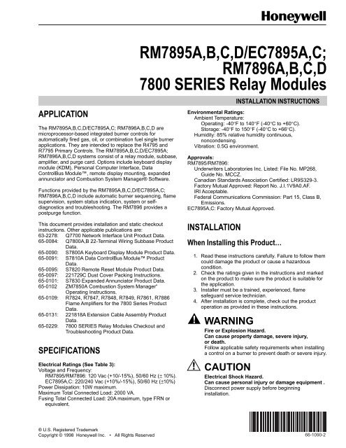
APPLICATION<br />
The RM7895A,B,C,D/EC7895A,C; RM7896A,B,C,D are<br />
microprocessor-based integrated burner controls for<br />
automatically fired gas, oil, or combination fuel single burner<br />
applications. They are intended to replace the R4795 and<br />
R7795 Primary Controls. The RM7895A,B,C,D/EC7895A;<br />
RM7896A,B,C,D systems consist of a <strong>relay</strong> module, subbase,<br />
amplifier, and purge card. Options include keyboard display<br />
module (KDM), Personal Computer Interface, Data<br />
ControlBus Module, remote display mounting, expanded<br />
annunciator and Combustion System Manager® Software.<br />
Functions provided by the RM7895A,B,C,D/EC7895A,C;<br />
RM7896A,B,C,D include automatic burner sequencing, flame<br />
supervision, system status indication, system or selfdiagnostics<br />
and troubleshooting. The RM7896 provides a<br />
postpurge function.<br />
RM7895A,B,C,D/EC7895A,C;<br />
RM7896A,B,C,D<br />
<strong>7800</strong> SERIES Relay Modules<br />
INSTALLATION INSTRUCTIONS<br />
Environmental Ratings:<br />
Ambient Temperature:<br />
Operating: -40°F to 140°F (-40°C to +60°C).<br />
Storage: -40°F to 150°F (-40°C to +66°C).<br />
Humidity: 85% relative humidity continuous,<br />
noncondensing.<br />
Vibration: 0.5G environment.<br />
Approvals:<br />
RM7895/RM7896:<br />
Underwriters Laboratories Inc. Listed: File No. MP268,<br />
Guide No. MCCZ.<br />
Canadian Standards Association Certified: LR9S329-3.<br />
Factory Mutual Approved: Report No. J.I.1V9A0.AF.<br />
IRI Acceptable.<br />
Federal Communications Commission: Part 15, Class B,<br />
Emissions.<br />
EC7895A,C: Factory Mutual Approved.<br />
This document provides installation and static checkout<br />
instructions. Other applicable publications are:<br />
63-2278: Q7700 Network Interface Unit Product Data.<br />
65-0084: Q<strong>7800</strong>A,B 22-Terminal Wiring Subbase Product<br />
Data.<br />
65-0090: S<strong>7800</strong>A Keyboard Display Module Product Data.<br />
65-0091: S7810A Data ControlBus Module Product<br />
Data.<br />
65-0095: S7820 Remote Reset Module Product Data.<br />
65-0097: 221729C Dust Cover Packing Instructions.<br />
65-0101: S7830 Expanded Annunciator Product Data.<br />
65-0102 ZM7850A Combustion System Manager“<br />
Operating Instructions.<br />
65-0109: R7824, R7847, R7848, R7849, R7861, R7886<br />
Flame Amplifiers for the <strong>7800</strong> Series Product<br />
Data.<br />
65-0131: 221818A Extension Cable Assembly Product<br />
Data.<br />
65-0229: <strong>7800</strong> SERIES Relay Modules Checkout and<br />
Troubleshooting Product Data.<br />
SPECIFICATIONS<br />
Electrical Ratings (See Table 3):<br />
Voltage and Frequency:<br />
RM7895/RM7896: 120 Vac (+10/-15%), 50/60 Hz (± 10%).<br />
EC7895A,C: 220/240 Vac (+10%/-15%), 50/60 Hz (±10%)<br />
Power Dissipation: 10W maximum.<br />
Maximum Total Connected Load: 2000 VA.<br />
Fusing Total Connected Load: 20A maximum, type FRN or<br />
equivalent.<br />
INSTALLATION<br />
When Installing this Product…<br />
1. Read these instructions carefully. Failure to follow them<br />
could damage the product or cause a hazardous<br />
condition.<br />
2. Check the ratings given in the instructions and marked<br />
on the product to make sure the product is suitable for<br />
the application.<br />
3. Installer must be a trained, experienced, flame<br />
safeguard service technician.<br />
4. After installation is complete, check out the product<br />
operation as provided in these instructions.<br />
WARNING<br />
Fire or Explosion Hazard.<br />
Can cause property damage, severe injury,<br />
or death.<br />
Follow applicable safety requirements when installing<br />
a control on a burner to prevent death or severe injury.<br />
CAUTION<br />
Electrical Shock Hazard.<br />
Can cause personal injury or damage equipment .<br />
Disconnect power supply before beginning<br />
installation.<br />
® U.S. Registered Trademark<br />
Copyright © 1998 Honeywell Inc. • All Rights Reserved<br />
66-1090-2
RM7895A,B,C,D/EC7895A,C; RM7896A,B,C,D <strong>7800</strong> SERIES RELAY MODULES<br />
IMPORTANT<br />
1. Wiring connections for the <strong>relay</strong> <strong>modules</strong> are unique;<br />
refer to Fig. 2 and 3 or the appropriate Specifications<br />
for proper subbase wiring.<br />
2. Wiring must comply with all applicable codes,<br />
ordinances and regulations.<br />
3. Wiring must comply with NEC Class 1 (Line Voltage)<br />
wiring.<br />
4. Loads connected to the RM7895A,B,C,D/<br />
EC7895A,C; RM7896A,B,C,D must not exceed<br />
those listed on the RM7895A,B,C,D/EC7895A,C;<br />
RM7896A,B,C,D label or the Specifications; see<br />
Table 1.<br />
5. Limits and interlocks must be rated to<br />
simultaneously carry and break current to the<br />
ignition transformer, pilot valve, and main fuel<br />
valve(s).<br />
6. All external timers must be listed or componentrecognized<br />
by authorities who have proper<br />
jurisdiction.<br />
7. For on-off gas-fired systems, some authorities who<br />
have jurisdiction prohibit the wiring of any limit or<br />
operating contacts in <strong>series</strong> between the flame<br />
safeguard control and the main fuel valve(s).<br />
8. Two flame detectors can be connected in parallel<br />
with the exception of Infrared Flame Detectors<br />
(C7015).<br />
9. This equipment generates, uses and can radiate<br />
radio frequency energy and, if not installed and used<br />
in accordance with the instructions, can cause<br />
interference with radio communications. It has been<br />
tested and found to comply with the limits for a Class<br />
B computing device of Part 15 of FCC rules, which<br />
are designed to provide reasonable protection<br />
against such interference when operated in a<br />
commercial environment. Operation of this<br />
equipment in a residential area may cause<br />
interference, in which case, the users, at their own<br />
expense, may be required to take whatever<br />
measures are required to correct this interference.<br />
10. This digital apparatus does not exceed the Class B<br />
limits for radio noise for digital apparatus set out in<br />
the Radio Interference Regulations of the Canadian<br />
Department of Communications.<br />
Location<br />
Humidity<br />
Install the <strong>relay</strong> module where the relative humidity never<br />
reaches the saturation point. The <strong>relay</strong> module is designed to<br />
operate in a maximum 85% relative humidity continuous,<br />
noncondensing, moisture environment. Condensing moisture<br />
can cause a safety shutdown.<br />
Vibration<br />
Do not install the <strong>relay</strong> module where it can be subjected to<br />
vibration in excess of 0.5G continuous maximum vibration.<br />
Weather<br />
The <strong>relay</strong> module is not designed to be weather tight. When<br />
installed outdoors, protect the <strong>relay</strong> module in an approved<br />
weather-tight enclosure.<br />
Mounting Wiring Subbase<br />
1. Mount the subbase in any position except horizontally<br />
with the bifurcated contacts pointing down. The<br />
standard vertical position is recommended. Any other<br />
position decreases the maximum ambient temperature<br />
rating.<br />
2. Select a location on a wall, burner or electrical panel.<br />
The Q<strong>7800</strong> can be mounted directly in the control<br />
cabinet. Be sure to allow adequate clearance for<br />
service, installation, access or removal of the<br />
RM7895A,B,C,D/EC7895A,C; RM7896A,B,C,D,<br />
expanded annunciator, keyboard display module, flame<br />
amplifier, flame amplifier signal voltage probes, run/test<br />
switch, electrical signal voltage probes and electrical<br />
field connections.<br />
3. For surface mounting, use the back of the subbase as a<br />
template to mark the four screw locations. Then drill the<br />
pilot holes.<br />
4. Securely mount the subbase using four no. 6 screws<br />
(not provided).<br />
Wiring Subbase<br />
CAUTION<br />
Electrical Shock Hazard.<br />
Can cause personal injury or damage equipment.<br />
Disconnect the power supply before beginning<br />
installation.<br />
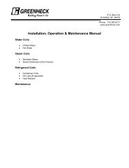
The internal block diagram of the RM7895A,B,C,D/<br />
EC7895A,C;RM7896A,B,C,D is shown in Fig. 1.<br />
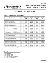
1. For proper subbase wiring and sequence chart, refer to<br />
Fig. 2 and 3.<br />
2. For remote wiring of the Keyboard Display Module,<br />
refer to the Specifications for the Keyboard Display<br />
Module (65-0090), Network Interface Unit (63-2278),<br />
Data ControlBus Module (65-0091) or Extension<br />
Cable Assembly (65-0131).<br />
3. Disconnect the power supply from the main disconnect<br />
before beginning installation to prevent electrical shock<br />
and equipment damage. More than one disconnect can<br />
be required.<br />
4. All wiring must comply with all applicable electrical<br />
codes, ordinances and regulations. Wiring, where<br />
required, must comply with NEC, Class 1 (Line Voltage)<br />
wiring.<br />
5. For recommended wire size and type, see Table 1.<br />
6. For recommended grounding practices, see Table 2.<br />
66-1090—2<br />
2
RM7895A,B,C,D/EC7895A,C; RM7896A,B,C,D <strong>7800</strong> SERIES RELAY MODULES<br />
DDL<br />
2 REMOTE<br />
FIELD WIRING<br />
COMMUNICATIONS 3 RESET<br />
INTERNAL WIRING<br />
L1 L2<br />
(HOT)<br />
1<br />
5<br />
RM7895, RM7896: 120 VAC, 50/60 HZ.<br />
EC7895A,C: 220-240 VAC, 50/60 HZ.<br />
PLUG-IN PURGE<br />
CONFIGURATION<br />
TIMER CARD<br />
JUMPERS<br />
TEST<br />
FLAME SIGNAL<br />
JACK<br />
RUN/TEST<br />
SWITCH<br />
F<br />
PLUG-IN<br />
MICROCOMPUTER<br />
TEST FLAME<br />
AMPLIFIER<br />
G<br />
RESET<br />
22<br />
PUSHBUTTON<br />
2K<br />
RELAY<br />
RELAY 3K<br />
STATUS<br />
DRIVE 4K<br />
FEEDBACK<br />
CIRCUIT<br />
AND LINE<br />
5K<br />
VOLTAGE<br />
6K<br />
INPUTS<br />
7K<br />
SAFETY RELAY<br />
CIRCUIT<br />
1K<br />
STATUS LEDs<br />
CONTROL<br />
POWER SUPPLY POWER<br />
1K1 2K1 5K1<br />
LIMITS<br />
6<br />
CONTROLLER<br />
7<br />
4K1<br />
LOCKOUT<br />
INTERLOCK<br />
10<br />
8<br />
IGNITION<br />
PILOT<br />
(INCLUDING<br />
7K1<br />
AIRFLOW SWITCH)<br />
21<br />
2ND STAGE<br />
VALVE<br />
2K2<br />
9 MAIN VALVE<br />
6K1<br />
4 BLOWER<br />
3K1<br />
3 ALARM<br />
DDL<br />
OPTIONAL KEYBOARD<br />
DISPLAY MODULE<br />
RS485<br />
INDICATES FEEDBACK SENSING<br />
TO RELAY STATUS FEEDBACK<br />
AND LINE VOLT INPUTS<br />
1<br />
L2<br />
2<br />
1<br />
2<br />
PROVIDE DISCONNECT MEANS AND<br />
OVERLOAD PROTECTION AS REQUIRED.<br />
FOR EC7895, MUST USE A 220 TO 240 VAC<br />
TO 120 VAC, 10 VA MINIMUM STEPDOWN<br />
TRANSFORMER (NOT PROVIDED) MUST<br />
BE USED TO DRIVE THE SHUTTER.<br />
M5110F<br />
Fig. 1. Internal block diagram of RM7895A,B,C,D/EC7895A,C; RM7896A,B,C,D<br />
(see Fig. 2 and 3 for detailed wiring instructions).<br />
3 66-1090—2
RM7895A,B,C,D/EC7895A,C; RM7896A,B,C,D <strong>7800</strong> SERIES RELAY MODULES<br />
Q<strong>7800</strong><br />
G<br />
12<br />
FOR DIRECT SPARK IGNITION<br />
(OIL OR GAS)<br />
LINE VOLTAGE ALARM<br />
L2<br />
3<br />
13<br />
14<br />
10<br />
8<br />
IGNITION<br />
TRANSFORMER<br />
MAIN VALVE<br />
L2<br />
BURNER MOTOR<br />
(BLOWER)<br />
4<br />
15<br />
5<br />
(L1)<br />
16<br />
BURNER<br />
CONTROLLER/LIMITS<br />
6<br />
17<br />
LOCKOUT INTERLOCK<br />
(INCLUDING<br />
AIRFLOW SWITCH)<br />
7<br />
18<br />
2<br />
INTERMITTENT<br />
PILOT/IGNITION<br />
8<br />
19<br />
MAIN FUEL VALVE(S)<br />
9<br />
20<br />
IGNITION<br />
10<br />
21<br />
FLAME DETECTOR<br />
4<br />
3<br />
F<br />
22<br />
MASTER<br />
SWITCH<br />
L1<br />
(HOT)<br />
1<br />
L2<br />
LED<br />
DISPLAY<br />
INITIATE<br />
POWER<br />
STANDBY<br />
POWER<br />
00 00 00<br />
TIMED<br />
START PURGE<br />
POWER POWER<br />
PFEP<br />
4 OR 10 SEC<br />
POWER<br />
RUN<br />
POWER<br />
7<br />
POST PURGE<br />
15 SEC<br />
POWER<br />
STANDBY<br />
POWER<br />
PILOT<br />
FLAME<br />
MAIN<br />
PILOT<br />
FLAME<br />
MAIN<br />
PILOT<br />
FLAME<br />
MAIN<br />
ALARM<br />
ALARM<br />
ALARM<br />
BURNER<br />
START<br />
BURNER/BLOWER MOTOR<br />
10<br />
IGN<br />
5<br />
4<br />
7<br />
IGN/ PILOT<br />
8<br />
MAIN VALVE<br />
9<br />
OPERATING<br />
CONTROLS<br />
AND<br />
INTERLOCKS<br />
FLAME<br />
SIGNAL<br />
6<br />
AIRFLOW SW CHECK<br />
LIMITS AND BURNER CONTROLLER CLOSED<br />
SAFE START CHECK<br />
LOCKOUT INTERLOCK CLOSED<br />
6<br />
FLAME<br />
PROVING<br />
L1 TO 6<br />
TO 7<br />
AFSC<br />
SSC<br />
1<br />
2<br />
3<br />
RM7895, RM7896: 120 VAC , 50/60 HZ; EC7895: 220-240 VAC,<br />
50/60 HZ POWER SUPPLY. PROVIDE DISCONNECT MEANS<br />
AND OVERLOAD PROTECTION AS REQUIRED.<br />
DO NOT CONNECT ANY WIRES TO UNUSED TERMINALS.<br />
FOR EC7895, A 220 TO 240 VAC TO 120 VAC, 10 VA MINIMUM STEPDOWN<br />
TRANSFORMER (NOT PROVIDED) MUST BE USED TO DRIVE THE SHUTTER.<br />
4 SEE FLAME DETECTOR SPECIFICATIONS FOR CORRECT WIRING.<br />
FOR RM7895A1048 (ONLY), IGNITION TERMINAL 10<br />
IS DE-ENERGIZED WHEN FLAME IS PROVEN.<br />
AIRFLOW SWITCH CHECK FEATURE IS FOR THE RM7895B,RM7896B.<br />
7 RM7896A,B ONLY.<br />
Fig. 2. Wiring subbase and sequence chart for RM7895A,B/EC7895A; RM7896A,B.<br />
5<br />
6<br />
M15123A<br />
66-1090—2<br />
4
RM7895A,B,C,D/EC7895A,C; RM7896A,B,C,D <strong>7800</strong> SERIES RELAY MODULES<br />
Q<strong>7800</strong><br />
G<br />
12<br />
FOR DIRECT SPARK IGNITION<br />
(OIL OR GAS)<br />
L2<br />
13<br />
10<br />
IGNITION<br />
TRANSFORMER<br />
LINE VOLTAGE<br />
ALARM<br />
3<br />
14<br />
8<br />
L2<br />
BURNER MOTOR<br />
(BLOWER)<br />
4<br />
15<br />
9<br />
MAIN VALVE<br />
5<br />
(L1)<br />
16<br />
BURNER<br />
CONTROLLER/LIMITS<br />
6<br />
17<br />
LOCKOUT INTERLOCK<br />
(INCLUDING<br />
AIRFLOW SWITCH).<br />
7<br />
18<br />
2<br />
10 SEC. INTERRUPTED<br />
PILOT/IGNITION<br />
8<br />
19<br />
MAIN FUEL VALVE(S)<br />
IGNITION<br />
9<br />
10<br />
20<br />
21<br />
DELAYED<br />
(2ND STAGE)<br />
MAIN VALVE<br />
FLAME DETECTOR<br />
4<br />
3<br />
F<br />
22<br />
MASTER<br />
SWITCH<br />
L1<br />
(HOT)<br />
1<br />
L2<br />
LED<br />
DISPLAY<br />
INITIATE<br />
POWER<br />
STANDBY<br />
POWER<br />
00 00 00<br />
START<br />
POWER<br />
TIMED<br />
PURGE<br />
POWER<br />
PFEP<br />
4 OR 10 SEC<br />
POWER<br />
MFEP<br />
POWER<br />
RUN<br />
POWER<br />
6<br />
POST PURGE<br />
15SEC<br />
POWER<br />
STANDBY<br />
POWER<br />
PILOT<br />
PILOT<br />
PILOT<br />
PILOT<br />
FLAME<br />
FLAME<br />
FLAME<br />
FLAME<br />
MAIN<br />
MAIN<br />
MAIN<br />
MAIN<br />
ALARM<br />
ALARM<br />
ALARM<br />
ALARM<br />
BURNER<br />
START<br />
BURNER/BLOWER MOTOR<br />
IGN.<br />
10<br />
4<br />
6<br />
10 SEC. IGN./ PILOT<br />
8<br />
MAIN VALVE<br />
9<br />
2ND STAGE MAIN 21<br />
OPERATING<br />
CONTROLS<br />
AND<br />
INTERLOCKS<br />
5 AIRFLOW SW. CHECK<br />
LIMITS AND BURNER CONTROLLER CLOSED<br />
LOCKOUT INTERLOCK CLOSED<br />
6<br />
L1 TO 6<br />
TO 7<br />
AFSC<br />
FLAME<br />
SIGNAL<br />
SAFE START CHECK FLAME PROVING SSC<br />
1<br />
RM7895, RM7896: 120 VAC , 50/60 HZ; EC7895: 220-240 VAC,<br />
50/60 HZ POWER SUPPLY. PROVIDE DISCONNECT<br />
MEANS AND OVERLOAD PROTECTION AS REQUIRED.<br />
4 SEE FLAME DETECTOR SPECIFICATIONS FOR CORRECT WIRING.<br />
5 AIRFLOW SWITCH CHECK FEATURE IS FOR THE RM7895D, RM7896D.<br />
2<br />
DO NOT CONNECT ANY WIRES TO UNUSED TERMINALS.<br />
6<br />
RM7896C,D ONLY.<br />
3<br />
FOR EC7895, A 220 TO 240 VAC TO 120 VAC, 10 VA MINIMUM STEPDOWN<br />
TRANSFORMER (NOT PROVIDED) MUST BE USED TO DRIVE THE SHUTTER.<br />
M15124A<br />
Fig. 3. Wiring subbase and sequence chart for RM7895C,D/EC7895C,D; RM7896C,D.<br />
5 66-1090—2
RM7895A,B,C,D/EC7895A,C; RM7896A,B,C,D <strong>7800</strong> SERIES RELAY MODULES<br />
Table 1. Recommended Wire Sizes and Part Numbers.<br />
Application Recommended Wire Size Recommended Part Numbers<br />
Line voltage terminals 14, 16, or 18 AWG copper conductor, 600 volt TTW60C, THW75C, THHN90C.<br />
insulation, moisture-resistant wire.<br />
Keyboard Display<br />
Module<br />
Data ControlBus a<br />
Module<br />
Remote Reset Module<br />
Comunications Interface<br />
ControlBus Modulea<br />
13 Vdc full-wave rectified<br />
transformer power input.<br />
22 AWG two-wire twisted pair with ground, or fivewire.<br />
22 AWG two-wire twisted pair with ground, or fivewire.<br />
Belden 8723 shielded cable or equivalent.<br />
Belden 8723 shielded cable or equivalent.<br />
22 AWG two-wire twisted pair, insulated for low —<br />
voltage.<br />
22 AWG two-wire twisted pair with ground. Belden 8723 shielded cable or equivalent.<br />
18 AWG wire insulated for voltages and temperatures<br />
for given application.<br />
TTW60C, THW75C, THHN90C.<br />
a The KDM, Data ControlBus Module (for remote mounting or communications) or Communication Interface ControlBus<br />
Module must be wired in daisy chain configuration, 1(a)-1(a), 2(b)-2(b), 3(c)-3(c). The order of interconnection of all the<br />
devices listed above is not important. Be aware that <strong>modules</strong> on the closest and farthest end of the daisy chain configuration<br />
string require a 120 ohm (1/4 watt minimum) resistor termination across terminals 1 and 2 of the electrical connectors for<br />
connections over 100 feet (31 meters).<br />
Ground type<br />
Table 2. Recommended Grounding Practices.<br />
Recommended Practice<br />
Earth ground (subbase and <strong>relay</strong> module). 1. Use to provide a connection between the subbase and the control<br />
panel of the equipment. Earth ground must be capable of conducting<br />
enough current to blow the 20A fuse (or breaker) in the event of an<br />
internal short circuit.<br />
2. Use wide straps or brackets to provide minimum length, maximum<br />
surface area ground conductors. If a leadwire is required, use 14<br />
AWG copper wire.<br />
3. Make sure that mechanically tightened joints along the ground path<br />
are free of nonconductive coatings and protected against corrosion on<br />
mating surfaces.<br />
Signal ground (Keyboard Display Module, Data<br />
Controlbus Module, Communications Interface<br />
ControlBus Module).<br />
Use the shield of the signal wire to ground the device to the signal ground<br />
terminals 3(c) of each device. Connect the shield at both ends of the daisy<br />
chain to earth ground.<br />
7. Recommended wire routing of leadwires:<br />
a. Do not run high voltage ignition transformer wires<br />
in the same conduit with the flame detector, Data<br />
ControlBus Module, or Remote Reset Module<br />
wiring.<br />
b. Do not route flame detector, Data ControlBus<br />
Module, or Remote Reset Module leadwires in<br />
conduit with line voltage circuits.<br />
c. Enclose flame detector leadwires without armor<br />
cable in metal cable or conduit.<br />
d. Follow directions in flame detector, Data<br />
ControlBus Module, or Remote Reset Module<br />
Instructions.<br />
8. The KDM is powered from a low voltage, energy limited<br />
source. It can be mounted outside of a control panel if it<br />
is protected from mechanical damage.<br />
NOTE:<br />
A 13 Vdc power supply must be used any time<br />
more than one KDM is used. A maximum of<br />
two KDM, Data ControlBus Modules or<br />
S7810B Multi-Drop Switch Modules are<br />
allowed in any combination.<br />
9. Maximum wire lengths:<br />
a. RM7895A,B,C,D/EC7895A,C; RM7896A,B,C,D<br />
leadwires: The maximum leadwire length is 300<br />
feet (93 meters) to terminal inputs (Control,<br />
Running/Lockout Interlock).<br />
b. Flame Detector leadwires: The maximum flame<br />
sensor leadwire length is limited by the flame<br />
signal strength.<br />
c. Remote Reset leadwires: The maximum length of<br />
wire is 1000 feet (305 meters) to a Remote Reset<br />
pushbutton.<br />
d. Data ControlBus Module: The maximum Data<br />
ControlBus Module cable length depends on<br />
the number of system <strong>modules</strong> connected, the<br />
noise conditions and the cable used. The<br />
maximum length of all Data ControlBus Module<br />
interconnecting wire is 4000 feet (1219 meters).<br />
10. Be sure loads do not exceed the terminal ratings. Refer<br />
to the label on the RM7895A,B,C,D/EC7895A,C;<br />
RM7896A,B,C,D or to the terminal ratings in Table 3.<br />
66-1090—2<br />
6
RM7895A,B,C,D/EC7895A,C; RM7896A,B,C,D <strong>7800</strong> SERIES RELAY MODULES<br />
Final Wiring Check<br />
1. Check the power supply circuit. The voltage and<br />
frequency tolerance must match those of the<br />
RM7895A,B,C,D/EC7895A,C; RM7896A,B,C,D. A<br />
separate power supply circuit can be required for the<br />
RM7895A,B,C,D/EC7895A,C; RM7896A,B,C,D. Add<br />
the required disconnect means and overload protection.<br />
2. Check all wiring circuits and complete Static Checkout<br />
in Table 6 before installing the RM7895A,B,C,D/<br />
EC7895A,C; RM7896A,B,C,D on the subbase.<br />
3. Install all electrical connectors.<br />
4. Restore power to the panel.<br />
Table 3. Terminal Ratings.<br />
Terminal<br />
Ratings<br />
No Description RM7895/RM7896 EC7895<br />
G Flame Sensor Ground — —<br />
Earth G Earth Ground a — —<br />
L2(N) Line Voltage Common — —<br />
3 Alarm 120 Vac, 1A pilot duty. 220-240 Vac, 1A pilot duty.<br />
4 Burner Motor 120 Vac, 9.8 AFL, 58.8 ALR<br />
(inrush).<br />
5 Line Voltage Supply (L1) 120 Vac (+10/-15%),<br />
50 or 60 Hz (+/- 10%).b<br />
220-240 Vac, 4A at PF = 0.5, 20A inrush.<br />
220-240 Vac (+10/-15%)<br />
50 or 60 Hz (±10%.)<br />
6 Burner Controller and Limits 120 Vac, 1 mA. 220-240 Vac, 1 mA.<br />
7 Lockout Interlock 120 Vac, 8A run, 43A inrush. 8A at PF = 0.5, 40A inrush, 2A at PF = 0.2.<br />
8 Pilot Valve/Ignition 120 Vac c 220-240 Vac, 4A at PF = 0.5, 20A inrush.<br />
9 Main Fuel Valve 120 Vac c 220-240 Vac, 4A at PF = 0.5, 20A inrush.<br />
10 Ignition 120 Vac c 220-240 Vac, 2A at PF = 0.2.<br />
F(11) Flame Sensor 60 to 220 Vac, current limited. 60 to 220 Vac, current limited.<br />
12 to 20 Unused — —<br />
21 2nd Stage Main Valve<br />
(EC7895C, RM7895C,D;<br />
RM7896C,D)<br />
120 Vac c 220-240 Vac, 4A at PF = 0.5, 20A inrush.<br />
22 Shutter 120 Vac, 0.5A 220-240 Vac d<br />
a See Table 2.<br />
b 2000 VA maximum load connected to RM7895A,B,C,D/EC7895A,C/RM7896A,B,C,D Assembly.<br />
c See Tables 4 and 5.<br />
d Requires 220-240 Vac, 10 VA minimum, stepdown transformer to operate the shutter.<br />
Table 4. Combinations for Terminals 8, 9, 10 and 21.<br />
Combination No. Pilot Fuel 8 Main 9 Ignition 10 Delayed Main Valve 21<br />
1 C F No Load No Load<br />
2 B F No Load No Load<br />
3 F a No Load A No Load<br />
4 F F A No Load<br />
5 F a No Load A F<br />
6 D F A No Load<br />
7 D a No Load A D<br />
8 D D A No Load<br />
9 D a No Load A D<br />
a RM7895C,D; EC7895C only, jumper terminals 8 to 9.<br />
7 66-1090—2
RM7895A,B,C,D/EC7895A,C; RM7896A,B,C,D <strong>7800</strong> SERIES RELAY MODULES<br />
Table 5. Composition of each Combination.<br />
A B C D F<br />
4.5A ignition 50 VA Pilot Duty plus 4.5A ignition. 180 VA Ignition plus<br />
motor valves with:<br />
660 VA inrush,<br />
360 VA open,<br />
240 VA hold.<br />
2A Pilot Duty<br />
65 VA Pilot Duty plus<br />
motor valves with:<br />
3850 VA inrush,<br />
700 VA open,<br />
250 VA hold.<br />
STATIC CHECKOUT<br />
After checking all wiring, perform this checkout before<br />
installing the EC7895A,C/RM7895A,B,C,D/RM7896A,B,C,D<br />
on the subbase. These tests verify the Q<strong>7800</strong> Wiring<br />
Subbase is wired correctly, and the external controllers, limits,<br />
interlocks, actuators, valves, transformers, motors and other<br />
devices are operating properly.<br />
WARNING<br />
Fire or Explosion Hazard.<br />
Can cause property damage, severe injury or<br />
death.<br />
Close all manual fuel shutoff valve(s) before starting<br />
these tests.<br />
Use extreme care while testing the system. Line<br />
voltage is present on most terminal connections when<br />
power is on.<br />
Ensure proper selection of configuration jumpers before<br />
starting the burner operation.<br />
CAUTION<br />
Electrical Hazard.<br />
Can cause equipment damage or failure.<br />
Do not perform a dielectric test with the <strong>relay</strong> module<br />
installed. Internal surge protectors can break down,<br />
allowing <strong>relay</strong> module to fail the dielectric test and<br />
destroy the internal lightning and high current<br />
protection.<br />
1. Open the master switch before installing or removing a<br />
jumper on the subbase.<br />
2. Before continuing to the next test, be sure to remove<br />
the test jumper(s) used in the previous test.<br />
3. Replace all limits and interlocks that are not operating<br />
properly. Do not bypass limits and interlocks.<br />
Equipment Recommended<br />
1. Voltmeter (1M ohm/volt minimum sensitivity) set on the<br />
0 to 300 Vac scale.<br />
2. Two jumper wires, no. 14 wire, insulated, 12 in.<br />
(304.8 mm) long with insulated alligator clips at both<br />
ends.<br />
General Instructions<br />
1. Perform all applicable tests listed in Static Checkout,<br />
Table 6, in the order listed.<br />
2. Make sure all manual fuel shutoff valve(s) are closed.<br />
3. For each test, open the master switch and install the<br />
jumper wire(s) between the subbase wiring terminals<br />
listed in the Test Jumpers column.<br />
4. Close the master switch before observing operation.<br />
5. Read the voltage between the subbase wiring terminals<br />
listed in the Voltmeter column.<br />
6. If there is no voltage or the operation is abnormal,<br />
check the circuits and external devices as described in<br />
the last column.<br />
7. Check all wiring for correct connections, tight terminal<br />
screws, correct wire, and proper wiring techniques.<br />
Replace all damaged or incorrectly sized wires.<br />
8. Replace faulty controllers, limits, interlocks, actuators,<br />
valves, transformers, motors and other devices, as<br />
required.<br />
9. Make sure normal operation is obtained for each<br />
required test before continuing the checkout.<br />
10. After completing each test, be sure to open the master<br />
power switch and remove the test jumper(s) before<br />
proceeding to the next test.<br />
WARNING<br />
Explosion hazard.<br />
Can cause serious injury or death.<br />
Be sure all manual fuel shutoff valves are closed.<br />
66-1090—2<br />
8
RM7895A,B,C,D/EC7895A,C; RM7896A,B,C,D <strong>7800</strong> SERIES RELAY MODULES<br />
Test<br />
No.<br />
Relay<br />
Module<br />
Model<br />
Table 6. Static Checkout.<br />
Test<br />
Jumpers Voltmeter Normal Operation<br />
If Operation is Abnormal, Check<br />
Items Listed Below<br />
1 All None 5-L2 Line voltage at terminal 5. 1. Master switch.<br />
2. Power connected to master switch.<br />
3. Overload protection (fuse, circuit<br />
breaker, etc.) has not opened<br />
power line.<br />
2 All None 6-L2 Line voltage at terminal 6. 1. Limits.<br />
2. Burner controller.<br />
3 All 4-5 7-L2 1. Burner motor (fan or blower)<br />
starts.<br />
2. Line voltage at terminal 7<br />
within 10 seconds.<br />
4 All 5-10 — 1. Ignition spark (if ignition<br />
transformer is connected to<br />
terminal 10).<br />
1. Burner motor circuit.<br />
a. Manual switch of burner motor.<br />
b. Burner motor power supply,<br />
overload protection and<br />
starter.<br />
c. Burner motor.<br />
1. Watch for spark or listen for buzz.<br />
a. Ignition electrodes are clean.<br />
b. Ignition transformer is okay.<br />
5 All 5-8 — 1. Ignition spark (if ignition<br />
transformer is connected to<br />
terminal 8).<br />
2. Automatic pilot valve opens (if<br />
connected to terminal 8).<br />
1. Watch for spark or listen for buzz.<br />
2. Listen for click or feel head of valve<br />
for activation.<br />
a. Actuator if used.<br />
b. Pilot valve.<br />
NOTE: Refer to wiring diagram of<br />
system being tested.<br />
6 All 5-9 — Automatic fuel valve(s) open(s).<br />
If using direct spark ignition, check<br />
first stage fuel valve(s) instead of<br />
pilot valve.<br />
7 EC7895CR<br />
M7895C,D,<br />
RM7896C,D<br />
5-21 — Automatic second stage main fuel<br />
valve(s) opens.<br />
Same as test 5. If using direct spark<br />
ignition, check first stage fuel valve(s)<br />
instead of pilot valve.<br />
1. Listen for and observe operation of<br />
second stage main fuel valve(s)<br />
and actuator(s).<br />
2. Valve(s) and actuator(s).<br />
8 All 5-3 — Alarm (if used) turns on. 1. Alarm.<br />
Final All<br />
CAUTION<br />
Equipment Damage Hazard.<br />
Can cause equipment damage.<br />
After completing these tests, open master switch and remove all test jumpers from subbase<br />
terminals. Also remove bypass jumpers, if used, from low fuel pressure limits.<br />
Mounting RM7895A,B,C,D/EC7895A,C;<br />
RM7896A,B,C,D Relay Module<br />
1. Mount the RM7895A,B,C,D/EC7895A,C;<br />
RM7896A,B,C,D vertically on the Q<strong>7800</strong> Subbase or<br />
mount horizontally with the knife blade terminals<br />
pointing down. When mounted on the Q<strong>7800</strong>A, the<br />
RM7895A,B,C,D/EC7895A,C; RM7896A,B,C,D must<br />
be in an electrical enclosure.<br />
2. When mounting in an electrical enclosure, provide<br />
adequate clearance for servicing, installation and<br />
removal of the RM7895A,B,C,D/EC7895A,C;<br />
RM7896A,B,C,D, KDM, flame amplifier, flame amplifier<br />
signal voltage probes, electrical signal voltage probes<br />
and electrical connections.<br />
a. Allow an additional two inches (51 mm) below the<br />
RM7895A,B,C,D/EC7895A,C; RM7896A,B,C,D<br />
for the flame amplifier mounting.<br />
b. Allow an optional three-inch (76 mm) minimum on<br />
both sides of the RM7895A,B,C,D/EC7895A,C;<br />
RM7896A,B,C,D for electrical signal voltage<br />
probes.<br />
3. Make sure no subbase wiring is projecting beyond the<br />
terminal blocks. Tuck in wiring against the back of the<br />
subbase so it does not interfere with the knife blade<br />
terminals or bifurcated contacts.<br />
IMPORTANT<br />
The RM7895A,B,C,D/EC7895A,C; RM7896A,B,C,D<br />
must be installed with a plug-in motion rather than a<br />
hinge action.<br />
9 66-1090—2
RM7895A,B,C,D/EC7895A,C; RM7896A,B,C,D <strong>7800</strong> SERIES RELAY MODULES<br />
4. Mount the RM7895A,B,C,D/EC7895A,C;<br />
RM7896A,B,C,D by aligning the four L-shaped corner<br />
guides and knife blade terminals with the bifurcated<br />
contacts on the wiring subbase and securely tightening<br />
the two screws without deforming the plastic.<br />
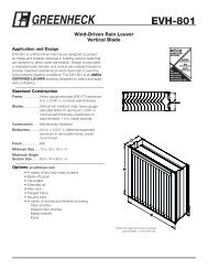
Mounting Other System Components (Fig. 4)<br />
Refer to the applicable specifications for mounting other<br />
system components.<br />
PRINCIPAL TECHNICAL FEATURES<br />
The RM/EC7895, RM7896 provides all customary flame<br />
safeguard functions as well as significant advancements in<br />
safety, annunciation, and system diagnostics.<br />
Safety Shutdown (Lockout) Occurs if:<br />
1. INITIATE PERIOD<br />
a. Purge card is not installed or removed.<br />
b. Purge card is bad.<br />
c. Configuration jumpers have been changed (after<br />
200 hours).<br />
d. AC line power errors occurred, see Operation.<br />
e. Four minute INITIATE period has been exceeded.<br />
2. STANDBY PERIOD<br />
a. Airflow lockout feature is enabled and the airflow<br />
switch does not close after ten seconds or within<br />
the specified purge card timing.<br />
b. Flame signal is detected after 30 seconds.<br />
c. Ignition/pilot valve/intermittent pilot valve terminal<br />
is energized.<br />
d. Main valve terminal is energized.<br />
e. Delayed (2nd stage) main valve terminal is<br />
energized (RM7895C,D/EC7895C; RM7896C,D).<br />
f. Internal system fault occurred.<br />
g. Purge card is removed.<br />
h. Purge card is bad.<br />
3. PREPURGE PERIOD<br />
a. Airflow lockout feature is enabled and the airflow<br />
switch opens.<br />
b. Ignition/pilot valve terminal is not energized.<br />
c. No flame present at end of PFEP.<br />
d. Main valve terminal is energized.<br />
e. Delayed (2nd stage) main valve terminal is<br />
energized (RM7895C,D/EC7895C; RM7896C,D).<br />
f. Internal system fault occurred.<br />
g. Purge card is removed.<br />
h. Purge card is bad.<br />
WIRING<br />
SUBBASE<br />
RUN/TEST (C,D ONLY)<br />
SWITCH<br />
HONEYWELL<br />
RELAY<br />
MODULE<br />
CONFIGURATION<br />
JUMPERS<br />
PURGE<br />
TIMER<br />
SEQUENCE<br />
STATUS<br />
LED PANEL<br />
DUST<br />
COVER<br />
RESET<br />
BUTTON<br />
POWER<br />
PILOT<br />
FLAME<br />
MAIN<br />
ALARM<br />
RESET<br />
CAPTIVE<br />
MOUNTING<br />
SCREW<br />
BURNER CONTROL<br />
FLAME<br />
AMPLIFIER<br />
M15122<br />
Fig. 4. RM7895A,B,C,D/EC7895A,C; RM7896A,B,C,D Relay Module exploded view.<br />
66-1090—2<br />
10
RM7895A,B,C,D/EC7895A,C; RM7896A,B,C,D <strong>7800</strong> SERIES RELAY MODULES<br />
4. PILOT FLAME ESTABLISHING PERIOD (PFEP)<br />
a. Airflow lockout feature is enabled and the airflow<br />
switch does not close after ten seconds or within<br />
the specified purge card timing.<br />
b. Flame signal is detected after 30 seconds.<br />
c. Ignition/pilot valve/intermittent pilot valve terminal<br />
is energized.<br />
d. Main valve terminal is energized.<br />
e. Delayed (2nd stage) main valve terminal is<br />
energized (RM7895C,D/EC7895C; RM7896C,D).<br />
f. Internal system fault occurred.<br />
g. Purge card is removed.<br />
h. Purge card is bad.<br />
5. MAIN FLAME ESTABLISHING PERIOD (MFEP)<br />
(RM7895C,D/EC7895C; RM7896C,D)<br />
a. Airflow lockout feature is enabled and the airflow<br />
switch opens.<br />
b. Ignition terminal is energized.<br />
c. Ignition/pilot valve terminal is not energized.<br />
d. Main valve terminal is not energized.<br />
e. Delayed main valve terminal is energized.<br />
f. No flame present at end of MFEP.<br />
g. Internal system fault occurred.<br />
h. Purge card is removed.<br />
i. Purge card is bad.<br />
6. RUN PERIOD<br />
a. No flame present.<br />
b. Airflow lockout feature is enabled and the airflow<br />
switch opens.<br />
c. Interrupted pilot valve terminal is energized<br />
(RM7895C,D/EC7895C; RM7896C,D).<br />
d. Main valve terminal is not energized.<br />
e. Delayed (2nd stage) main valve terminal is not<br />
energized (RM7895C,D/EC7895C; RM7896C,D).<br />
f. Internal system fault occurred.<br />
g. Purge card is removed.<br />
h. Purge card is bad.<br />
OPERATION<br />
Sequence of Operation<br />
The RM7895A,B,C,D/EC7895A,C; RM7896A,B,C,D has the<br />
operating sequences listed below; see Fig. 2 and 3. The<br />
RM7895A,B,C,D/EC7895A,C; RM7896A,B,C,D LED provide<br />
positive visual indication of the program sequence: POWER,<br />
PILOT, FLAME, MAIN and ALARM.<br />
Initiate<br />
The RM7895A,B,C,D/EC7895A,C; RM7896A,B,C,D Relay<br />
Module enters the INITIATE sequence when the <strong>relay</strong> module<br />
is powered. The RM7895A,B,C,D/EC7895A,C;<br />
RM7896A,B,C,D can also enter the INITIATE sequence if the<br />
<strong>relay</strong> module verifies voltage fluctuations of +10/-15% or<br />
frequency fluctuations of ±10% during any part of the<br />
operating sequence. The INITIATE sequence lasts for ten<br />
seconds unless the voltage or frequency tolerances are not<br />
met. When not met, a hold condition is initiated and displayed<br />
on the optional KDM for at least five seconds; when met, the<br />
INITIATE sequence restarts. If the condition is not corrected<br />
and the hold condition exists for four minutes, the<br />
RM7895A,B,C,D/EC7895A,C; RM7896A,B,C,D locks out.<br />
Causes for hold conditions in the INITIATE sequence:<br />
a. AC line dropout detection.<br />
b. AC line noise that can prevent a sufficient reading of<br />
the line voltage inputs.<br />
c. Low line voltage brownouts.<br />
The INITIATE sequence also delays the burner motor starter<br />
from being energized and de-energized from an intermittent<br />
AC line input or control input.<br />
Standby<br />
The RM7895A,B,C,D/EC7895A,C; RM7896A,B,C,D is ready<br />
to start an operating sequence when the operating control<br />
input determines a call for heat is present. The burner switch,<br />
limits, operating limit control and all microcomputer-monitored<br />
circuits must be in the correct state for the <strong>relay</strong> module to<br />
continue into the PREPURGE sequence.<br />
Normal Start-Up Prepurge<br />
The RM7895A,B,C,D/EC7895A,C; RM7896A,B,C,D Relay<br />
Module provides PREPURGE timing selectable from two<br />
seconds to thirty minutes with power applied and the<br />
operating control indicating a call for heat.<br />
1. The Airflow Interlock, burner switch, Run/Test switch<br />
and all microcomputer-monitored circuits must also be<br />
in the correct operating state.<br />
2. The motor output, terminal 4, is powered to start the<br />
PREPURGE sequence.<br />
3. The Airflow Interlock input closes ten seconds into<br />
PREPURGE or within the specified purge card timing;<br />
otherwise, a recycle to the beginning of PREPURGE or<br />
lockout occurs, depending on how the Airflow Switch<br />
selectable jumper (JR3) is configured.<br />
Ignition Trials<br />
1. Pilot Flame Establishing Period (PFEP):<br />
a. When the PFEP begins:<br />
(1) The pilot valve and ignition transformer,<br />
terminals 8 and 10, are energized. The<br />
RM7895A,B, EC7895A, and RM7896A,B have<br />
an intermittent pilot valve, terminal 8. The<br />
RM7895C,D, EC7895C, and RM7896C,D<br />
have an interrupted pilot valve, terminal 8.<br />
(2) Flame must be proven by the end of the ten<br />
second PFEP (four seconds if Configuration<br />
Jumper JR1 is clipped) to allow the sequence<br />
to continue. If a flame is not proven by the end<br />
of PFEP, a safety shutdown occurs.<br />
b. With flame proven, the ignition, terminal 10, is deenergized.<br />
2. Main Flame Establishing Period (MFEP):<br />
a. After the Ignition Trials, and with the presence of<br />
flame, the main fuel valve, terminal 9, is powered.<br />
If a flameout occurs, the <strong>relay</strong> module locks out or<br />
recycles (depending on status of jumper JR2)<br />
within 0.8 or 3 seconds, depending on the Flame<br />
Failure Response Time (FFRT) of the amplifier.<br />
b. The RM7895C,D/EC7895C, and RM7896C,D have<br />
a ten second MFEP. After the Ignition Trials and<br />
with the presence of flame, the main fuel valve,<br />
terminal 9, is powered. If a flameout occurs, the<br />
<strong>relay</strong> module locks out within 0.8 or 3 seconds,<br />
depending on the amplifier FFRT.<br />
11 66-1090—2
RM7895A,B,C,D/EC7895A,C; RM7896A,B,C,D <strong>7800</strong> SERIES RELAY MODULES<br />
Run<br />
1. The RM7895C,D, EC7895C, RM7896C,D has a<br />
delayed main valve that is energized once the RUN<br />
period is entered.<br />
2. The <strong>relay</strong> module is now in RUN and remains in RUN<br />
until the controller input, terminal 6, opens, indicating<br />
that the demand is satisfied or a limit has opened.<br />
Post Purge (RM7896A,B,C,D Only)<br />
RUN/TEST SWITCH<br />
(RM7895C,D;<br />
EC7895C;<br />
RM7896C,D)<br />
SEQUENCE<br />
STATUS<br />
LEDs<br />
CAPTIVE<br />
MOUNTING<br />
SCREW<br />
PLUG-IN<br />
PURGE<br />
CARD<br />
DUST<br />
COVER<br />
RELAY<br />
MODULE<br />
After demand is satisfied or a limit opens, de-energizing<br />
terminal 6, the Ignition/Pilot valve, main valve and delayed<br />
main valve, terminals 8, 9, and 21 are de-energized. The<br />
blower motor, terminal 4, remains powered for 15 seconds.<br />
Run/Test Switch (RM7895C,D/EC7895C;<br />
RM7896C,D only)<br />
The Run/Test Switch is located on the top side of the <strong>relay</strong><br />
module, see Fig. 5. The Run/Test Switch allows the burner<br />
sequence to be altered as follows:<br />
1. In the measured PREPURGE sequence, the Run/Test<br />
Switch, placed in the TEST position, causes the<br />
PREPURGE timing to stop.<br />
2. In the Pilot Flame Establishing Period, the Run/Test<br />
Switch, placed in the TEST position, stops the timer<br />
during the first eight seconds of a ten-second PFEP<br />
selection or during the first three seconds of a foursecond<br />
PFEP selection. It also allows for pilot turndown<br />
test and other burner adjustments. This activates<br />
a fifteen-second flameout timer that permits pilot flame<br />
adjustment without nuisance safety shutdowns. The<br />
Run/Test Switch is ignored during PFEP for the C and<br />
D <strong>relay</strong> <strong>modules</strong> if terminals 8 and 9 or 9 and 21 are<br />
jumpered.<br />
IMPORTANT<br />
When the <strong>relay</strong> module is switched to the TEST<br />
mode, it stops and holds at the next Run/Test Switch<br />
point in the operating sequence. Make sure that the<br />
Run/Test Switch is in the RUN position before<br />
leaving the installation.<br />
SETTINGS AND ADJUSTMENTS<br />
Selectable Site-Configurable Jumpers<br />
The <strong>relay</strong> module has three site-configurable jumper options,<br />
see Fig. 6 and Table 7. If necessary, clip the site-configurable<br />
jumpers with side cutters and remove the resistors from the<br />
<strong>relay</strong> module.<br />
SERVICE NOTE:<br />
Clipping and removing a site-configurable<br />
jumper enhances the level of safety.<br />
RESET<br />
PUSHBUTTON<br />
FLAME<br />
SIMULATOR INPUT<br />
Fig. 5. Sequence Status LEDs.<br />
SELECTABLE CONFIGURATION JUMPERS<br />
RUN/TEST SWITCH<br />
(EC7895C; RM7895C,D; RM7896C,D)<br />
M7553A<br />
Fig. 6. Selectable site-configurable jumpers.<br />
Table 7. Site-Configurable Jumper Options.<br />
Jumper<br />
Number Description Intact Clipped<br />
JR1 a<br />
Pilot Flame Establishing<br />
Period (PFEP)<br />
10<br />
seconds<br />
FLAME<br />
AMPLIFIER<br />
FLAME CURRENT<br />
TEST JACKS M7552A<br />
4<br />
seconds<br />
JR2 Flame Failure Action Recycle Lockout<br />
JR3 Airflow Switch (ILK) Recycle Lockout<br />
Failure<br />
a The RM7895C1020 has a fixed PFEP of ten seconds and<br />
does not have jumper JR1.<br />
IMPORTANT<br />
Clipping and removing a jumper after 200 hours of<br />
operation causes a nonresettable Fault 110. The<br />
<strong>relay</strong> module must then be replaced.<br />
Home and Building Control<br />
Honeywell Inc.<br />
Honeywell Plaza<br />
P.O. Box 524<br />
Minneapolis MN 55408-0524<br />
66-1090—2<br />
66-1090–2 R.R. Rev. 9-98<br />
Home and Building Control<br />
Honeywell Limited-Honeywell Limitée<br />
155 Gordon Baker Road<br />
North York, Ontario<br />
M2H 3N7<br />
Printed in U.S.A. on recycled<br />
paper containing at least 10%<br />
post-consumer 12 paper fibers.<br />
www.honeywell.com