7800 series relay modules - Greenheck
7800 series relay modules - Greenheck
7800 series relay modules - Greenheck
You also want an ePaper? Increase the reach of your titles
YUMPU automatically turns print PDFs into web optimized ePapers that Google loves.
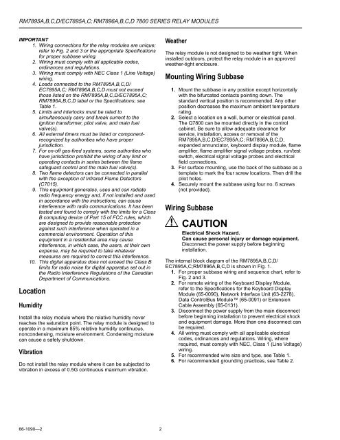
RM7895A,B,C,D/EC7895A,C; RM7896A,B,C,D <strong>7800</strong> SERIES RELAY MODULES<br />
IMPORTANT<br />
1. Wiring connections for the <strong>relay</strong> <strong>modules</strong> are unique;<br />
refer to Fig. 2 and 3 or the appropriate Specifications<br />
for proper subbase wiring.<br />
2. Wiring must comply with all applicable codes,<br />
ordinances and regulations.<br />
3. Wiring must comply with NEC Class 1 (Line Voltage)<br />
wiring.<br />
4. Loads connected to the RM7895A,B,C,D/<br />
EC7895A,C; RM7896A,B,C,D must not exceed<br />
those listed on the RM7895A,B,C,D/EC7895A,C;<br />
RM7896A,B,C,D label or the Specifications; see<br />
Table 1.<br />
5. Limits and interlocks must be rated to<br />
simultaneously carry and break current to the<br />
ignition transformer, pilot valve, and main fuel<br />
valve(s).<br />
6. All external timers must be listed or componentrecognized<br />
by authorities who have proper<br />
jurisdiction.<br />
7. For on-off gas-fired systems, some authorities who<br />
have jurisdiction prohibit the wiring of any limit or<br />
operating contacts in <strong>series</strong> between the flame<br />
safeguard control and the main fuel valve(s).<br />
8. Two flame detectors can be connected in parallel<br />
with the exception of Infrared Flame Detectors<br />
(C7015).<br />
9. This equipment generates, uses and can radiate<br />
radio frequency energy and, if not installed and used<br />
in accordance with the instructions, can cause<br />
interference with radio communications. It has been<br />
tested and found to comply with the limits for a Class<br />
B computing device of Part 15 of FCC rules, which<br />
are designed to provide reasonable protection<br />
against such interference when operated in a<br />
commercial environment. Operation of this<br />
equipment in a residential area may cause<br />
interference, in which case, the users, at their own<br />
expense, may be required to take whatever<br />
measures are required to correct this interference.<br />
10. This digital apparatus does not exceed the Class B<br />
limits for radio noise for digital apparatus set out in<br />
the Radio Interference Regulations of the Canadian<br />
Department of Communications.<br />
Location<br />
Humidity<br />
Install the <strong>relay</strong> module where the relative humidity never<br />
reaches the saturation point. The <strong>relay</strong> module is designed to<br />
operate in a maximum 85% relative humidity continuous,<br />
noncondensing, moisture environment. Condensing moisture<br />
can cause a safety shutdown.<br />
Vibration<br />
Do not install the <strong>relay</strong> module where it can be subjected to<br />
vibration in excess of 0.5G continuous maximum vibration.<br />
Weather<br />
The <strong>relay</strong> module is not designed to be weather tight. When<br />
installed outdoors, protect the <strong>relay</strong> module in an approved<br />
weather-tight enclosure.<br />
Mounting Wiring Subbase<br />
1. Mount the subbase in any position except horizontally<br />
with the bifurcated contacts pointing down. The<br />
standard vertical position is recommended. Any other<br />
position decreases the maximum ambient temperature<br />
rating.<br />
2. Select a location on a wall, burner or electrical panel.<br />
The Q<strong>7800</strong> can be mounted directly in the control<br />
cabinet. Be sure to allow adequate clearance for<br />
service, installation, access or removal of the<br />
RM7895A,B,C,D/EC7895A,C; RM7896A,B,C,D,<br />
expanded annunciator, keyboard display module, flame<br />
amplifier, flame amplifier signal voltage probes, run/test<br />
switch, electrical signal voltage probes and electrical<br />
field connections.<br />
3. For surface mounting, use the back of the subbase as a<br />
template to mark the four screw locations. Then drill the<br />
pilot holes.<br />
4. Securely mount the subbase using four no. 6 screws<br />
(not provided).<br />
Wiring Subbase<br />
CAUTION<br />
Electrical Shock Hazard.<br />
Can cause personal injury or damage equipment.<br />
Disconnect the power supply before beginning<br />
installation.<br />
The internal block diagram of the RM7895A,B,C,D/<br />
EC7895A,C;RM7896A,B,C,D is shown in Fig. 1.<br />
1. For proper subbase wiring and sequence chart, refer to<br />
Fig. 2 and 3.<br />
2. For remote wiring of the Keyboard Display Module,<br />
refer to the Specifications for the Keyboard Display<br />
Module (65-0090), Network Interface Unit (63-2278),<br />
Data ControlBus Module (65-0091) or Extension<br />
Cable Assembly (65-0131).<br />
3. Disconnect the power supply from the main disconnect<br />
before beginning installation to prevent electrical shock<br />
and equipment damage. More than one disconnect can<br />
be required.<br />
4. All wiring must comply with all applicable electrical<br />
codes, ordinances and regulations. Wiring, where<br />
required, must comply with NEC, Class 1 (Line Voltage)<br />
wiring.<br />
5. For recommended wire size and type, see Table 1.<br />
6. For recommended grounding practices, see Table 2.<br />
66-1090—2<br />
2


