7800 series relay modules - Greenheck
7800 series relay modules - Greenheck
7800 series relay modules - Greenheck

You also want an ePaper? Increase the reach of your titles
YUMPU automatically turns print PDFs into web optimized ePapers that Google loves.
RM7895A,B,C,D/EC7895A,C; RM7896A,B,C,D <strong>7800</strong> SERIES RELAY MODULES<br />
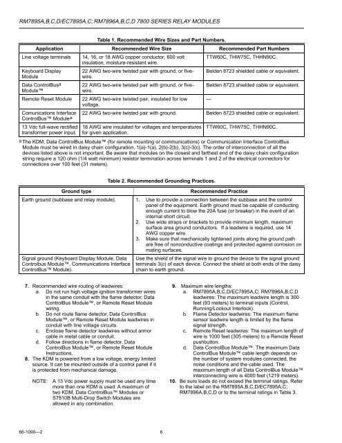
Table 1. Recommended Wire Sizes and Part Numbers.<br />
Application Recommended Wire Size Recommended Part Numbers<br />
Line voltage terminals 14, 16, or 18 AWG copper conductor, 600 volt TTW60C, THW75C, THHN90C.<br />
insulation, moisture-resistant wire.<br />
Keyboard Display<br />
Module<br />
Data ControlBus a<br />
Module<br />
Remote Reset Module<br />
Comunications Interface<br />
ControlBus Modulea<br />
13 Vdc full-wave rectified<br />
transformer power input.<br />
22 AWG two-wire twisted pair with ground, or fivewire.<br />
22 AWG two-wire twisted pair with ground, or fivewire.<br />
Belden 8723 shielded cable or equivalent.<br />
Belden 8723 shielded cable or equivalent.<br />
22 AWG two-wire twisted pair, insulated for low —<br />
voltage.<br />
22 AWG two-wire twisted pair with ground. Belden 8723 shielded cable or equivalent.<br />
18 AWG wire insulated for voltages and temperatures<br />
for given application.<br />
TTW60C, THW75C, THHN90C.<br />
a The KDM, Data ControlBus Module (for remote mounting or communications) or Communication Interface ControlBus<br />
Module must be wired in daisy chain configuration, 1(a)-1(a), 2(b)-2(b), 3(c)-3(c). The order of interconnection of all the<br />
devices listed above is not important. Be aware that <strong>modules</strong> on the closest and farthest end of the daisy chain configuration<br />
string require a 120 ohm (1/4 watt minimum) resistor termination across terminals 1 and 2 of the electrical connectors for<br />
connections over 100 feet (31 meters).<br />
Ground type<br />
Table 2. Recommended Grounding Practices.<br />
Recommended Practice<br />
Earth ground (subbase and <strong>relay</strong> module). 1. Use to provide a connection between the subbase and the control<br />
panel of the equipment. Earth ground must be capable of conducting<br />
enough current to blow the 20A fuse (or breaker) in the event of an<br />
internal short circuit.<br />
2. Use wide straps or brackets to provide minimum length, maximum<br />
surface area ground conductors. If a leadwire is required, use 14<br />
AWG copper wire.<br />
3. Make sure that mechanically tightened joints along the ground path<br />
are free of nonconductive coatings and protected against corrosion on<br />
mating surfaces.<br />
Signal ground (Keyboard Display Module, Data<br />
Controlbus Module, Communications Interface<br />
ControlBus Module).<br />
Use the shield of the signal wire to ground the device to the signal ground<br />
terminals 3(c) of each device. Connect the shield at both ends of the daisy<br />
chain to earth ground.<br />
7. Recommended wire routing of leadwires:<br />
a. Do not run high voltage ignition transformer wires<br />
in the same conduit with the flame detector, Data<br />
ControlBus Module, or Remote Reset Module<br />
wiring.<br />
b. Do not route flame detector, Data ControlBus<br />
Module, or Remote Reset Module leadwires in<br />
conduit with line voltage circuits.<br />
c. Enclose flame detector leadwires without armor<br />
cable in metal cable or conduit.<br />
d. Follow directions in flame detector, Data<br />
ControlBus Module, or Remote Reset Module<br />
Instructions.<br />
8. The KDM is powered from a low voltage, energy limited<br />
source. It can be mounted outside of a control panel if it<br />
is protected from mechanical damage.<br />
NOTE:<br />
A 13 Vdc power supply must be used any time<br />
more than one KDM is used. A maximum of<br />
two KDM, Data ControlBus Modules or<br />
S7810B Multi-Drop Switch Modules are<br />
allowed in any combination.<br />
9. Maximum wire lengths:<br />
a. RM7895A,B,C,D/EC7895A,C; RM7896A,B,C,D<br />
leadwires: The maximum leadwire length is 300<br />
feet (93 meters) to terminal inputs (Control,<br />
Running/Lockout Interlock).<br />
b. Flame Detector leadwires: The maximum flame<br />
sensor leadwire length is limited by the flame<br />
signal strength.<br />
c. Remote Reset leadwires: The maximum length of<br />
wire is 1000 feet (305 meters) to a Remote Reset<br />
pushbutton.<br />
d. Data ControlBus Module: The maximum Data<br />
ControlBus Module cable length depends on<br />
the number of system <strong>modules</strong> connected, the<br />
noise conditions and the cable used. The<br />
maximum length of all Data ControlBus Module<br />
interconnecting wire is 4000 feet (1219 meters).<br />
10. Be sure loads do not exceed the terminal ratings. Refer<br />
to the label on the RM7895A,B,C,D/EC7895A,C;<br />
RM7896A,B,C,D or to the terminal ratings in Table 3.<br />
66-1090—2<br />
6