7800 series relay modules - Greenheck
7800 series relay modules - Greenheck
7800 series relay modules - Greenheck

You also want an ePaper? Increase the reach of your titles
YUMPU automatically turns print PDFs into web optimized ePapers that Google loves.
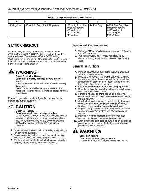
RM7895A,B,C,D/EC7895A,C; RM7896A,B,C,D <strong>7800</strong> SERIES RELAY MODULES<br />
Table 5. Composition of each Combination.<br />
A B C D F<br />
4.5A ignition 50 VA Pilot Duty plus 4.5A ignition. 180 VA Ignition plus<br />
motor valves with:<br />
660 VA inrush,<br />
360 VA open,<br />
240 VA hold.<br />
2A Pilot Duty<br />
65 VA Pilot Duty plus<br />
motor valves with:<br />
3850 VA inrush,<br />
700 VA open,<br />
250 VA hold.<br />
STATIC CHECKOUT<br />
After checking all wiring, perform this checkout before<br />
installing the EC7895A,C/RM7895A,B,C,D/RM7896A,B,C,D<br />
on the subbase. These tests verify the Q<strong>7800</strong> Wiring<br />
Subbase is wired correctly, and the external controllers, limits,<br />
interlocks, actuators, valves, transformers, motors and other<br />
devices are operating properly.<br />
WARNING<br />
Fire or Explosion Hazard.<br />
Can cause property damage, severe injury or<br />
death.<br />
Close all manual fuel shutoff valve(s) before starting<br />
these tests.<br />
Use extreme care while testing the system. Line<br />
voltage is present on most terminal connections when<br />
power is on.<br />
Ensure proper selection of configuration jumpers before<br />
starting the burner operation.<br />
CAUTION<br />
Electrical Hazard.<br />
Can cause equipment damage or failure.<br />
Do not perform a dielectric test with the <strong>relay</strong> module<br />
installed. Internal surge protectors can break down,<br />
allowing <strong>relay</strong> module to fail the dielectric test and<br />
destroy the internal lightning and high current<br />
protection.<br />
1. Open the master switch before installing or removing a<br />
jumper on the subbase.<br />
2. Before continuing to the next test, be sure to remove<br />
the test jumper(s) used in the previous test.<br />
3. Replace all limits and interlocks that are not operating<br />
properly. Do not bypass limits and interlocks.<br />
Equipment Recommended<br />
1. Voltmeter (1M ohm/volt minimum sensitivity) set on the<br />
0 to 300 Vac scale.<br />
2. Two jumper wires, no. 14 wire, insulated, 12 in.<br />
(304.8 mm) long with insulated alligator clips at both<br />
ends.<br />
General Instructions<br />
1. Perform all applicable tests listed in Static Checkout,<br />
Table 6, in the order listed.<br />
2. Make sure all manual fuel shutoff valve(s) are closed.<br />
3. For each test, open the master switch and install the<br />
jumper wire(s) between the subbase wiring terminals<br />
listed in the Test Jumpers column.<br />
4. Close the master switch before observing operation.<br />
5. Read the voltage between the subbase wiring terminals<br />
listed in the Voltmeter column.<br />
6. If there is no voltage or the operation is abnormal,<br />
check the circuits and external devices as described in<br />
the last column.<br />
7. Check all wiring for correct connections, tight terminal<br />
screws, correct wire, and proper wiring techniques.<br />
Replace all damaged or incorrectly sized wires.<br />
8. Replace faulty controllers, limits, interlocks, actuators,<br />
valves, transformers, motors and other devices, as<br />
required.<br />
9. Make sure normal operation is obtained for each<br />
required test before continuing the checkout.<br />
10. After completing each test, be sure to open the master<br />
power switch and remove the test jumper(s) before<br />
proceeding to the next test.<br />
WARNING<br />
Explosion hazard.<br />
Can cause serious injury or death.<br />
Be sure all manual fuel shutoff valves are closed.<br />
66-1090—2<br />
8