INDEX OPERATING MANUAL - Philippi
INDEX OPERATING MANUAL - Philippi
INDEX OPERATING MANUAL - Philippi

Create successful ePaper yourself
Turn your PDF publications into a flip-book with our unique Google optimized e-Paper software.
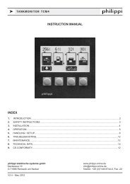
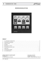
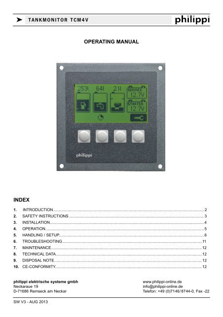
k TANKMONITOR TCM4V<br />
<strong>OPERATING</strong> <strong>MANUAL</strong><br />
<strong>INDEX</strong><br />
1. INTRODUCTION..........................................................................................................................................2<br />
2. SAFETY INSTRUCTIONS ........................................................................................................................... 3<br />
3. INSTALLATION.............................................................................................................................................4<br />
4. OPERATION................................................................................................................................................. 5<br />
5. HANDLING / SETUP.....................................................................................................................................6<br />
6. TROUBLESHOOTING................................................................................................................................11<br />
7. MAINTENANCE..........................................................................................................................................12<br />
8. TECHNICAL DATA......................................................................................................................................12<br />
9. DISPOSAL NOTE....................................................................................................................................... 12<br />
10. CE-CONFORMITY...................................................................................................................................... 12<br />
philippi elektrische systeme gmbh<br />
www.philippi-online.de<br />
Neckaraue 19<br />
info@philippi-online.de<br />
D-71686 Remseck am Neckar Telefon: +49 (0)7146/8744-0, Fax -22<br />
SW V3 - AUG 2013
k TANKMONITOR TCM4V<br />
1. INTRODUCTION<br />
Dear customer,<br />
thank you for buying the tankmonitor TCM 4V. This digital unit is state of the art in tank monitoring.<br />
On the large, illuminated display you can read:<br />
x the actual filling level of up to 4 tanks without battery voltages or<br />
x the actual filling level of up to 3 tanks and up to 2 battery voltages<br />
You have the possibility of:<br />
x adjusting an alarm threshold for each tank (full or empty alarm)<br />
x adjusting an alarm threshold for two batteries (min./max.)<br />
The tank levels are shown as a bar and in % or liters.<br />
The TCM 4V is easy to operate and well readable. You have a quick overview of up to 4 tank levels or<br />
1 - 3 tank levels and up to 2 battery voltages.<br />
For level-sensoring we recommend the sensors of our TGT / TGW - series, the ultrasonic sensors UTV and<br />
the fresh water flow sensor DFS. These sensors are not part of the purchased parts package.<br />
Sensors of other manufacturers can be connected as well; depending on the type you may need a hardware<br />
adaption of the TCM 4V at our company (sensor output 0-10 V, 4-20 mA).<br />
In the SETUP- menu the display will be configurated to the connected sensors. Also you have the possibility<br />
to adjust the Tank Monitor TCM 4V to your given tank - geometry to show the real tank filling level correctly.<br />
Please note: only when using the flow sensors DFS the shown display of liters is correct, because it measures<br />
the flowed liters. If you`re using other sensors, the TCM calculates the remaining tank capacity by<br />
the tank volume and the actual level. Depending on the accuracy of the sensors it cannot be litre-correct.<br />
1.1. PURPOSE<br />
The Tank Monitor TCM 4V can only be used with suitable tank sensors for low voltage purposes<br />
DC 10-30V. It is designed for the use on yachts or camper vans and must be used in an enclosed<br />
environment which is protected against rain, moisture, dust and condensation.<br />
Don`t use the Tank Monitor TCM 4V in places where there could be danger of explosion by gas or dust.<br />
1.2.CONTENT<br />
x Tank Monitor TCM 4V<br />
x Plug-in clamp MVSTBR12, Order-no..: 6 2179 2113<br />
x This Instruction Manual<br />
1.3. RECOMMENDED SENSORS (to be ordered separately)<br />
Fresh water:<br />
x Flow sensor DFS Order-no.: 7 0003 0304<br />
x Fresh water tank sensor TGW 200-800 Order-no.: 6 6011 7xxx<br />
Fuel:<br />
x Fuel tank sensor TGT 200-800 Order-no.: 6 6011 7xxx<br />
Page 2 SW V3 - AUG 2013
k TANKMONITOR TCM4V<br />
Grey Water / Waste Water:<br />
x Ultrasonic sensor UTV 20-80 Order-no.: 7 0219 35xx<br />
recommended accessories for ultrasonic sensors:<br />
x Focus tube UFT 40 (40cm long) Order-no.: 7 0219 9400<br />
x Focus tube UFT 80 (80cm long) Order-no.: 7 0219 9800<br />
x Distance ring UTS 25 (25mm high) Order-no.: 7 0219 9025<br />
x Distance ring UTS 50 (50mm high) Order-no.: 7 0219 9050<br />
1.4. WARRANTY<br />
philippi elektrische systeme gmbh grants a two year limited and non-transferable warranty for the first buyer of<br />
this equipment, commencing on the date of purchase and covers defects in manufacturing, parts and materials.<br />
Production or material defects will be corrected without costs if:<br />
x the equipment is sent to us at the expense of the sender<br />
x an Invoice or proof of purchase (copy) is included<br />
x the equipment was used for its intended purpose<br />
x no unauthorised parts were added, and the equipment was not exposed to extreme conditions<br />
Not included in the warranty are damages from:<br />
x overvoltage in the inputs or reverse polarity<br />
x ingress of liquids, vapours, condensation, etc<br />
x lightning<br />
Follow-up costs and normal wear and tear are not covered under warranty.<br />
In case of warranty the defect must be clearly specified. A detailed description of the<br />
failure will ease and speed up the repair.<br />
Please note that we cannot accept carriage forward deliveries.<br />
1.5 EXCLUSION OF LIABILITY<br />
Both adherence to the operating instructions, and the conditions and methods used during installation, use,<br />
and maintenance of the Tank Monitor TCM4V cannot be supervised by philippi electrical systems. Therefore<br />
we do not take any responsibility for loss, damage or costs, which develop due to incorrect installation and/or<br />
inappropriate use.<br />
1.6 QUALITY MANAGEMENT<br />
During the process of manufacturing all devices pass several checks, controls and tests. Production, controls<br />
and tests are due to given protocols. Each Tank Monitor TCM4V has its own serial number. Please do not<br />
remove this label.The assembly and testing of all TCM4V devices is carried out completely in our facilities at<br />
Remseck am Neckar / Germany.<br />
2 SAFETY REFERENCES<br />
x unauthorized changes to the equipment will invalidate the CE sign<br />
x the installation of the TCM4V may be made only by electrical specialists.<br />
x Important! Pay attention to the correct polarity of the batteries!<br />
This assembly and operating instruction is a component of the TCM4V package. It must be kept<br />
(for reference). Importantly: - for later maintenance work - and for the use of subsequent owners of the<br />
equipment.<br />
SW V3 - AUG 2013<br />
Page
k TANKMONITOR TCM4V<br />
3. INSTALLATION AND CONNECTION<br />
Please install the Tank Monitor TCM4V in a visible place, so that it can be read off at any time. The installation<br />
cutout is 88 x 88mm, the minimum installation depth is 40mm.<br />
The TCM4V supervises up to four tanks at the same time. If you have less than 4 tank sensors, start connecting<br />
the first tank sensor at terminal TG 1 (if you`re using two, connect them to TG 1 and TG 2 and so on).<br />
You can use both passive (resistance like TGT / TGW) and active (ultrasonic / UTV) sensors at the same<br />
time. For connection please have a look at the connection diagramms. See chapt. 3.1- 3.3.<br />
The flow sensor DFS can be connected either to terminal TG 1 or / and terminal TG 2!<br />
If you want to use tank sensors with an output of 4-20mA or 0-10V you need a hardware-adaption of<br />
the TCM4V at the manufacturer. Please contact us for details.<br />
The power supply for the TCM4V is either directly from the battery or from a power distribution panel. A wire of<br />
min. 1mm² cross section is recommended, which has to be fused (1A).<br />
The display is lit for 30s when you press a button. You can also connect the terminal “Light” to a switch and a<br />
12/24v DC positive supply, and switch it on and off manually<br />
Batt.2<br />
Batt.1<br />
TG 4<br />
TG 3<br />
TG 2<br />
TG 1<br />
GND -<br />
DFS +<br />
UTV +<br />
12/24V<br />
GND -<br />
Light<br />
3.1 CONNECTION OF ULTRASONIC SENSORS UTV AND OTHER ACTIVE SENSORS:<br />
TG 4<br />
TG 3<br />
TG 2<br />
TG 1<br />
GND -<br />
DFS +<br />
UTV +<br />
12/24V<br />
GND -<br />
Light<br />
ATTENTION:<br />
If the power supply of an ultrasonic sensor (red<br />
wire) is connected directly to the on board DC<br />
system, not on the terminal UTV+ the tank monitor<br />
TCM4V, this wire has to be fused by a 1A<br />
fuse!<br />
The negative wires of the tank sensors have to<br />
be connected directly to the terminal “GND-” in<br />
order to avoid wrong measurements.<br />
Page 4 SW V3 - AUG 2013
k TANKMONITOR TCM4V<br />
3.2 CONNECTION OF RESISTANCE SENSORS<br />
like series TRG, TGT, TGW and other<br />
3.3 CONNECTION OF THE FLOW SENSOR DFS<br />
DFS<br />
TG 4<br />
TG 3<br />
TG 2<br />
TG 1<br />
GND -<br />
DFS +<br />
UTV +<br />
12/24V<br />
GND -<br />
Light<br />
TG 4<br />
TG 3<br />
TG 2<br />
TG 1<br />
GND -<br />
DFS +<br />
UTV +<br />
12/24V<br />
GND -<br />
Light<br />
(2.DFS)<br />
4. OPERATION<br />
The main display shows the tank levels automatically after switching on. If a voltage higher than 1V is connected<br />
to the terminal Batt.1 and/or Batt.2 and the number of tanks is set between 1-3 tanks, a battery symbol with<br />
the relating name appears and the measured voltage will be shown. Batt.1 is shown above, Batt.2 below.<br />
In the SETUP-menu you can set each tank bar individually to the medium (fuel, water...), the volume, the type<br />
of sensor used, the compensation value for the tank-geometry and the alarm-threshold. In case of a power supply<br />
breakdown all of these settings are saved and are immediately available after switching on.<br />
All tank levels are measured each 5 seconds. The measured levels are shown in a bar diagram and additionally<br />
either in liters, percent or without either being shown. This can be adjusted in the SETUP-menu.<br />
If the displayed indication is “----”, the measured value of the related tank is out of an expected range or there is<br />
no sensor connected.<br />
4.1. TANK ALARM<br />
If an alarm is set you can see the threshold level as small horizontal lines at each side inside the tank graphic<br />
at the appropriate level. From this you can see easily if the tank level is in the acceptable range or not.<br />
For alarm thresholds over 50%, the "Full" alarm is used, so that a level over the threshold switches the alarm<br />
on<br />
For alarm thresholds from 0% to 50% the "Empty" - alarm is used, so that a level under the threshold switches<br />
the alarm on.<br />
The alarm is delayed by 15s. In case of an alarm the relating tank bar flashes. In addition the display illumination<br />
flashes and an acoustical alarm turns on for the period of 1 minute. This alarm can be cleared by pressing<br />
any button.<br />
SW V3 - AUG 2013 Page 5
k TANKMONITOR TCM4V<br />
4.2. BATTERY ALARM<br />
4.2.1 UNDERVOLTAGE ALARM Battery 1 / 2 (U1 / U2)<br />
If the battery voltage falls below the threshold for 30s, the relating battery symbol starts to flash. In addition the<br />
display illumination flashes and an acoustical alarm turns on for the period of 1 minute. This alarm can be cleared<br />
by pressing any button. Possible thresholds are between 10V and 31V.<br />
4.2.2 OVERVOLTAGE ALARM Battery 1 / 2 (U1 / U2)<br />
If the battery voltage rises above the set threshold for 30s, the relating battery symbol starts to flash. In addition<br />
the display illumination flashes and an acoustical alarm turns on for the period of 1 minute. This alarm can be<br />
cleared by pressing any button. Possible thresholds are between 11V and 32V.<br />
4.3 POWERSAVE MODE<br />
To reduce the current consumption of the tank measurement system when using ultrasonic sensors or other<br />
active sensors (50mA / sensor), you can choose the POWERSAVE MODE. In the Powersave Mode the measurement<br />
of the active sensors is carried out every 30 min.<br />
A measuring cycle lasts 5 minutes, thereby the sensors are scanned each 5 s.<br />
- At a power supply voltage between 11,5 - 13V a measuring cycle takes place every 30 minutes;<br />
- If the supply voltage is below 11,5V a measuring cycle takes place every 2 hours.<br />
A new measurement cycle is started always by pressing of any button. During the breaks the last measured<br />
values are shown.<br />
The Powersave Mode is activated / deactivated automatically if the power supply voltage is:<br />
- Above 13V the Powersave Mode is switched off;<br />
- Under 11,5V the Powersave Mode is switched on. The display illumination is also deacivated.<br />
At 24V- operation double values are applying.<br />
If the Powersave Mode is activated in the SETUP, the following symbol is shown at<br />
the bottom right of the display:<br />
Attention: when using the Powersave Mode, the filling level can fall under<br />
the alarm threshold during a cycle break without causing an alarm!<br />
5. HANDLING<br />
5.1 DISPLAY ILLUMINATION<br />
By pressing the push buttons the display illumination is lit during 30s. The display illumination can be activated<br />
also by connecting the terminal connection “Light” to a voltage of 12/24V.<br />
5.2 SETUP<br />
By pressing the right hand side button the Setup menu<br />
will be activated. In this menu you can change all values<br />
and settings.<br />
The highlighted line is ative for changes to be made.<br />
Page 6 SW V3 - AUG 2013
k TANKMONITOR TCM4V<br />
Following actions are activated by pressing:<br />
Arrow up:<br />
Arrow to right:<br />
Minus:<br />
Plus:<br />
Return:<br />
choice of the input line<br />
choice of the sub menu<br />
decreasing of the value<br />
increasing of the value<br />
save the values and return to the main display<br />
The SETUP menu can be locked by pressing the right hand side button (“tool”) for 10s. The “tool”<br />
disappears. By pressing the same button again for 10s the SETUP menu will be unlocked.<br />
5.2.1 ADJUSTMENTS MAIN MENU<br />
5.2.1.1 INDICATION Set Indication of the tank volume in liters (l)<br />
Set indication of the tank volume in percent (%)<br />
Set no numerical indication of the tank volume<br />
5.2.1.2 NUMBER OF TANKS Set number of the tanks shown (1 - 4 tanks), display of the voltage only<br />
if max. 3 tanks are set.<br />
5.2.1.3 TANK X See chapter 5.2.2 individual settings for each tank: tank volume in<br />
liters, tank type, sensor type, compensation valueand alarm level.<br />
5.2.1.4 POWERSAVE MODE 1 = on, 0 = off<br />
5.2.1.5 CONTRAST Display contrast attitude + = dimmer, - = brighter<br />
5.2.1.6 LANGUAGE Language in the Setup menu. Following languages are available:<br />
German / English / French<br />
5.2.1.7 NAME U1 (U2) Name of the related battery (Starter, Service...)<br />
5.2.1.8 ALARM U1/U2 min. Adjustment of the under-voltage alarm for battery 1 / 2<br />
5.2.1.9 ALARM U1/U2 max. Adjustment of the over-voltage alarm for battery 1 / 2<br />
5.2.1.10 INFO Software version, factory setting and test.<br />
If you want to reset to the factory setting, please press the “factory”<br />
button for 10 s, until an acoustic signal sounds.<br />
The “Test” - button is only for our internal service purposes.<br />
SW V3 - AUG 2013 Page 7
k TANKMONITOR TCM4V<br />
5.2.2 SETTINGS IN THE TANK SUB MENU:<br />
You can select the desired tank menu by pressing the button (arrow to the right):<br />
In the tank menu you can set the tank volume, the tank type (e.g. water, fuel, waste), the type of sensor, the<br />
alarm level and the compensation value (adjustment of the tank-geometry).<br />
If you set the type of sensor to a custom resistance sensor (User R) you have the opportunity to set the ohmvalues<br />
for 0%, 50% and 100%.<br />
If you have choosen the sensor type UTV 40/80, you can adjust the tank depth and an optional use of a<br />
distance ring UTS.<br />
5.2.2.1 VOLUME<br />
Adjustment of the tank volume by pressing the +/- - buttons. The volume is shown in liters.<br />
5.2.2.2 TANK TYPE<br />
There are 4 different tank symbols to choose from:<br />
Water Fuel Waste Water Grey water<br />
5.2.2.3 SENSOR<br />
Sensor name Sensor type Measuring range Attention<br />
TRG philippi TRG 6 steps (6-190 Ohm)<br />
TGX 10-180 (Ohm) philippi TGT / TGW 10..180 Ohm<br />
240 - 33 (Ohm) 240...33 Ohm UTR not possible!<br />
User R<br />
free adjustment of resistance range<br />
UTV/UTA philippi UTV 0,5..2,5V<br />
philippi UTA 4...20mA This requires a factory hardware modification !<br />
UTV 40/80 philippi UTV 40/UTV 80 0,5..2,5 V<br />
DFS (down) philippi DFS Flow sensor<br />
DFS (up) philippi DFS Flow sensor for water maker<br />
0 - 10 V 0...10 V This requires a factory hardware modification !<br />
PB42 5 bars sensor 4 levels Aux. hardware PB42 !<br />
Incorrect display information can occur due to not compatible parts and settings. In this case the value shown is<br />
“---”. Please ensure that the selected sensor type matches to the installed sensor.<br />
Page 8 SW V3 - AUG 2013
k TANKMONITOR TCM4V<br />
5.2.2.3.1 SENSOR TYPE UTV 40 / 80<br />
You need the following ultrasonic sensors:<br />
- tank depth (plus opt. distance ring UTS) equal or less than 40 cm: UTV40<br />
- tank depth (plus opt. distance ring UTS) greater than 40 cm: UTV80 (max. depth measurable : 80 cm)<br />
The depth of each tank can be adjusted in cm in the SETUP-menu. (1 inch = 2,5 cm)<br />
After selected the sensor type UTV 40/80 you have to set the UTV-type (40 or 80), a distance ring UTS (if installed),<br />
25 or 50mm, and the depth of the tank.<br />
:<br />
If the tank depth is more than 40 cm, you have to use<br />
and set the UTV80 sensor.<br />
To account for the dead-band of the ultrasonic sensor UTV (the range which is not measurable between the<br />
sensor and the surface of the liquid at the top of the tank) you can use a distance ring UTS 25 or UTS 50 to<br />
obtain a completely full reading. If you`re using such a distance ring UTS, you have to set this too.<br />
If the tank depth plus the distance ring is equal or less than 40 cm you need an UTV 40; greater than 40 cm an<br />
UTV 80. If the UTV40 is chosen, the adjustable depth incl. distance ring is always less than 40cm.<br />
ATTENTION! If the total of tank depth and height of the distance ring is greater than 40 cm, you have<br />
to use an UTV 80! (f.e. tank depth is 37 cm and distance ring is 5 cm = total depth is 42 cm)<br />
You can use only ultrasonic sensors UTV40 or UTV80 for this setting!<br />
SW V3 - AUG 2013 Page 9
k TANKMONITOR TCM4V<br />
5.2.2.3.2 SENSOR TYPE USER R<br />
Does your tank sensor have a characteristic curve which isn’t selectable in the Setup menu? In this mode you<br />
can enter the values for your sensor using the "User R" setting, as described below<br />
Sensors: this mode can only be used in combination with passive resistance-sensors, not in combination<br />
with active / capacitive sensors! (like UTR) !<br />
The resistance-values for 3 levels (0%, 50%, 100%) have<br />
to be entered in the setup. For that you have to measure<br />
the resistance of your sensor when the tank level is empty,<br />
half-full and full by using an ohm-meter. Then you can<br />
enter these values in the submenu of the according tank at<br />
0%, 50% and 100%, of tank capacity.<br />
The TCM4V calculates the actual level on the basis of this<br />
values.<br />
5.2.2.3.3 SENSOR TYPE DFS<br />
If a Flow Sensor DFS is connected and set at tank 1 and/or 2, you can see the following symbol under the relating<br />
tank in the main display:<br />
Because the Flow Sensor DFS cannot detect when the tank is refilled, the operator must<br />
adjust the level manually after filling. By pressing the relavent button you can enter directly<br />
into the menu where you can adjust the filled level accordingly.<br />
When water is flowing through the Flow Sensor DFS, this symbol is rotating. You can choose between two<br />
directional options for the DFS. The DFS with an arrow down empties the tank; the DFS with arrow up is filling.<br />
The filling type is useful if you`re using a watermaker and you want to know the produced volume.<br />
5.2.2.4 ALARM LEVEL<br />
You can adjust the alarm threshold for each tank separately.<br />
Alarm level 0 % Alarm off<br />
1..50 % Empty-alarm: if the level falls below the selected threshold the<br />
alarm will be activated. The activation is delayed by 15s.<br />
51... 99 % Full-alarm: if the level rises above the selected threshold the alarm<br />
will be activated. The activation is delayed by 15s.<br />
Attention: when using the Powersave Mode, the filling level can fall under the alarm threshold during a<br />
cycle break without causing an alarm!<br />
Page 10 SW V3 - AUG 2013
k TANKMONITOR TCM4V<br />
5.2.2.5 COMPENSATION / ADJUSTMENT TO THE GEOMETRY OF THE TANK<br />
With non-rectangular tanks, the level height is not proportional to the content of<br />
liquid in the tank. By means of the "Compensation" value, this can be allowed<br />
for in the display. The Compensation value changes the tank characteristic in<br />
such a way that the indicated level is approximated to the geometry of the tank.<br />
The value to be entered is the half-height percentage by volume of a full tank<br />
The examples on the left show what Compensation value (K) would be entered<br />
as an approximation for tanks of several common geometric shapes.<br />
If your tank geometry deviates greatly from those shown on the left, then the<br />
Compensation value can be determined by the formula below.<br />
The Compensation value is found by dividing the liquid capacity at half the tank<br />
height, by the capacity of the tank when full, multiplied by 100.<br />
Capacity of half level height<br />
Correction value K = ------------------------------------ x 100<br />
Level of fuel in the tank entirely<br />
Example: The tank has a total volume of 150 L with a maximum filling height<br />
(tank height) of 50 cm.<br />
In order to determine the Compensation value, the tank is filled to the<br />
half-tank height (= 25 cm), and it is found to require 65L to fill to this level.<br />
Using the formula, the Compensation value is found to be:<br />
K = 65 l/150 l x 100 = 43<br />
The number 43 is then entered as the Compensation value in Setup.<br />
6. TROUBLESHOOTING<br />
u If the tank monitor shows wrong values or (---), please first check the sensor and that the electrical connections<br />
are good. Check also the wiring between the sensor and the tank monitor, as this is the main source of<br />
problems<br />
u If the reading from an ultrasonic sensor UTV is incorrect, check the power supply voltage at the sensor. This<br />
must be at least 10V (see technical data of the tank sensor<br />
u If you can't see the SETUP (“Tool”) button, the Setup may be locked. To unlock, you will have to press the<br />
right-hand side button for 10 seconds. The “tool” button will appear and you can then enter the Setup menu.<br />
SW V3 - AUG 2013 Page 11
k TANKMONITOR TCM4V<br />
7. MAINTENANCE<br />
The Tank Monitor TCM 4V does not request special maintenance. The front panel can be cleaned with a damp<br />
cloth without using agressive detergents.<br />
8. TECHNICAL DATA<br />
Power supply<br />
Power consumption<br />
Dimensions:<br />
Installation cutout:<br />
DC 10-30 Volt<br />
8mA when using resistance sensors,<br />
60mA if the display is lit (12V)<br />
12mA when using a flow sensor DFS<br />
when using ultrasonic sensors UTV:<br />
50 mA per sensor (without Powersave mode)<br />
105 x 105 x 40 mm<br />
88 x 88 mm<br />
9. DISPOSAL NOTE<br />
Please take care of your local directives on waste electrical and electronic equipment. Please use<br />
collection points for waste electrical and electronic equipment.<br />
10. DECLARATION OF CONFORMITY<br />
This device fulfills the requirements of the European regulation:<br />
2004/108/EG “ElectroMagnetic Compatibility”<br />
Immunity EN 61000-6-1<br />
Emission EN 61000-6-3<br />
The conformity to this regulation is certified by the CE - sign.<br />
Page 12 SW V3 - AUG 2013