Linear and Circular Dichroism - Hinds Instruments
Linear and Circular Dichroism - Hinds Instruments
Linear and Circular Dichroism - Hinds Instruments

Create successful ePaper yourself
Turn your PDF publications into a flip-book with our unique Google optimized e-Paper software.
LINEAR & CIRCULAR<br />
DICHROISM<br />
PHOTOELASTIC MODULATORS<br />
APPLICATION NOTE<br />
T E C H N O L O G Y F O R P O L A R I Z A T I O N M E A S U R E M E N T<br />
LINEAR & CIRCULAR DICHROISM<br />
BY DR. THEODORE C. OAKBERG<br />
The PEM photoelastic modulator is well suited for experiments which measure linear dichroism<br />
(LD) or circular dichroism (CD). The modulator has an RS-232 computer interface which enables<br />
the peak retardation level to be varied under computer control in synchronization with a scanning<br />
monochromator. The interface allows the computer to monitor the status of the modulator as well.<br />
<strong>Linear</strong> dichroism is the differential absorption between two orthogonal components of linear<br />
polarized light. 1, 2 This phenomenon occurs with certain natural crystals, with stretched polymers<br />
<strong>and</strong> with other non-isotropic samples. The techniques for reflectance difference spectroscopy or<br />
reflectance anisotropy spectroscopy are similar to linear dichroism (see PEM Newsletter #9).<br />
<strong>Circular</strong> dichroism is the differential absorption between left <strong>and</strong> right circular polarized light<br />
components. This occurs naturally with chiral compounds, that is, those molecules which exhibit<br />
“mirror isomerism” (left <strong>and</strong> right-h<strong>and</strong>edness).<br />
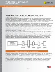
Both LD <strong>and</strong> CD can be measured with the same apparatus, shown below.<br />
<br />
<br />
<br />
<br />
<br />
<br />
<br />
<br />
<br />
<br />
<br />
<br />
<br />
<br />
<br />
<br />
<br />
<br />
<br />
<br />
EXPERIMENTAL SET-UP FOR LINEAR AND CIRCULAR DICHROISM<br />
Light from the monochromatic light source is polarized at an angle of 45° with respect to the<br />
modulator axis. Light coming from the modulator alternates between two orthogonal linear<br />
polarization states, or between the two senses of circular polarized light, depending on the peak<br />
retardation of the modulator.<br />
For linear dichroism the sample should be oriented so that a natural dichroic axis is at 45° to the<br />
modulator axis. The detector output is an electrical signal whose average (DC) voltage is proportional<br />
to the amount of light reaching the detector. The AC portion of the signal (proportional to the LD<br />
effect) is at twice the modulator frequency (2f).<br />
No special orientation of the sample is needed for circular dichroism samples. The AC signal<br />
(proportional to the CD effect) is at the modulator frequency (f). The average or DC voltage is<br />
proportional to the amount of light reaching the detector.
LINEAR & CIRCULAR<br />
DICHROISM<br />
PHOTOELASTIC MODULATORS<br />
APPLICATION NOTE<br />
The preamplifier provides current to voltage conversion <strong>and</strong> buffers the output for wide frequency<br />
response. (<strong>Hinds</strong> provides photodiode detectors which provide proper impedance matching <strong>and</strong><br />
frequency response, e.g. DC to 1 MHz.) The PEM-100 controller determines the peak retardation<br />
of the modulator. This is traditionally chosen to be half-wave retardation for LD experiments <strong>and</strong><br />
quarter-wave retardation for CD measurement. Use of an intermediate value of retardation (0.383<br />
waves) permits simultaneous measurement of LD <strong>and</strong> CD. 1<br />
The signal conditioner (<strong>Hinds</strong> Model SCU) provides amplification <strong>and</strong> derives a broad-b<strong>and</strong> AC signal<br />
<strong>and</strong> a low-pass or DC signal. The AC signal goes to a lock-in amplifier, where detection of the signal<br />
is accomplished by phase sensitive detection, using a reference signal (f or 2f) from the modulator<br />
controller. The output is an analog voltage proportional to the desired f or 2f signal component.<br />
The electrical signal obtained from the lock-in amplifier is dependent on the intensity of the light used<br />
in the experiment. Dividing the lock-in amplifier output by the DC or lowpass signal from the lock-in<br />
gives a signal which is directly proportional to the desired LD or CD effect. This may be expressed by<br />
the relationship<br />
<br />
V 2f or V 1f<br />
V DC V DC<br />
The calculation of the ratio of the AC voltage <strong>and</strong> the DC voltage may be done using a ratio circuit<br />
(such as is provided in many commercial lock-in amplifiers) or may be done in a computer, after the<br />
AC <strong>and</strong> DC signal components have been digitized.<br />
References:<br />
1. Hipps, K.W. <strong>and</strong> Crosby, G.A., Applications of the Photoelastic Modulator to Polarization<br />
Spectroscopy, Journal of Physical Chemistry, 83, 555, 1979.<br />
2. Drake, Alex F., Polarisation modulation the measurement of linear <strong>and</strong> circular dichroism, J.<br />
Phys. E: Sci Instrum. 19, 1986.<br />
<strong>Hinds</strong> <strong>Instruments</strong>, Inc / 7245 NW Evergreen Pkwy / Hillsboro, OR 97124 / USA<br />
T: 503.690.2000 / F: 503.690.3000 / sales@hindsinstruments.com / www.hindsinstruments.com<br />
PEMlabs is a Trademark of <strong>Hinds</strong> <strong>Instruments</strong>, Inc. Manufactured in USA<br />
© 2005, 2009, 2010 <strong>Hinds</strong> <strong>Instruments</strong>, Inc. All rights reserved. Printed in USA