magneto-optic kerr effect magneto-optic kerr effect - Hinds Instruments
magneto-optic kerr effect magneto-optic kerr effect - Hinds Instruments
magneto-optic kerr effect magneto-optic kerr effect - Hinds Instruments
You also want an ePaper? Increase the reach of your titles
YUMPU automatically turns print PDFs into web optimized ePapers that Google loves.
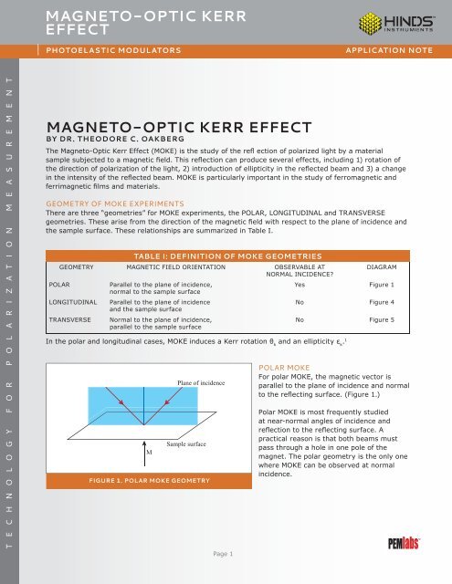
MAGNETO-OPTIC KERREFFECTPHOTOELASTIC MODULATORSAPPLICATION NOTET E C H N O L O G Y F O R P O L A R I Z A T I O N M E A S U R E M E N TMAGNETO-OPTIC KERR EFFECTBY DR. THEODORE C. OAKBERGThe Magneto-Optic Kerr Effect (MOKE) is the study of the refl ection of polarized light by a materialsample subjected to a magnetic field. This reflection can produce several <strong>effect</strong>s, including 1) rotation ofthe direction of polarization of the light, 2) introduction of ellipticity in the reflected beam and 3) a changein the intensity of the reflected beam. MOKE is particularly important in the study of ferromagnetic andferrimagnetic films and materials.GEOMETRY OF MOKE EXPERIMENTSThere are three “geometries” for MOKE experiments, the POLAR, LONGITUDINAL and TRANSVERSEgeometries. These arise from the direction of the magnetic field with respect to the plane of incidence andthe sample surface. These relationships are summarized in Table I.TABLE I: DEFINITION OF MOKE GEOMETRIESGEOMETRY MAGNETIC FIELD ORIENTATION OBSERVABLE ATDIAGRAMNORMAL INCIDENCE?POLARParallel to the plane of incidence,Yes Figure 1normal to the sample surfaceLONGITUDINAL Parallel to the plane of incidenceNo Figure 4and the sample surfaceTRANSVERSE Normal to the plane of incidence,parallel to the sample surfaceNo Figure 5In the polar and longitudinal cases, MOKE induces a Kerr rotation θ kand an ellipticity ε k. 1MPlane of incidenceSample surfaceFIGURE 1. POLAR MOKE GEOMETRYPage 1POLAR MOKEFor polar MOKE, the magnetic vector isparallel to the plane of incidence and normalto the reflecting surface. (Figure 1.)Polar MOKE is most frequently studiedat near-normal angles of incidence andreflection to the reflecting surface. Apractical reason is that both beams mustpass through a hole in one pole of themagnet. The polar geometry is the only onewhere MOKE can be observed at normalincidence.
MAGNETO-OPTIC KERREFFECTPHOTOELASTIC MODULATORSAPPLICATION NOTELaserPolarizer, 0°Atkinson 2 has shown one experimental setup for polarMOKE. (Figure 2)DetectorAnalyzer, 45°PEM, 0°MagnetSampleAfter passing through the analyzer to a detector, thedetector signal goes to two lock-in amplifiers and adigital voltmeter, then to a computer. (Figure 3) Someexperimenters put the 45° polarizer and the PEM at 0°before the sample and the analyzer polarizer at 0° after thesample. 3FIGURE 2. OPTICAL BENCH SETUPFOR POLAR MOKEThe operation of this system may be analyzed usingMueller matrices and Fourier series. The Kerr rotationangle θ and the Kerr ellipticity ε kare typically very smallnumbers, therefore small angle approximations may beused. The intensity of light (as a function of time) arrivingat the detector may be calculated. (See Appendix A for thederivation.)DetectorLIA (1f)where I 0represents the “average” or DC intensity, ω = 2πfis the angular frequency of the PEM oscillations and A 0, theretardation amplitude of the PEM. Using a Fourier seriesexpansion to represent this equation and keeping only thefirst three terms,LIA (2f)ComputerThe second term is part of the DC term and may beneglected for either or both of two reasons: 1) θ kis a verysmall number and/or 2) A 0= 2.405 radians, in which caseJ 0=0.DVM (DC)FIGURE 3. ELECTRONIC BLOCK DIAGRAMFOR MOKEThree voltages are measured: V DC, V 1fand V 2f. It istraditional to form the ratios of the AC term to the DC term,since by doing so the experiment becomes immune to fluctuations in the light intensity, changes in transmission,etc. ThusThe factor √2 arises since lock-in amplifiers display therms voltage, whereas the theory is written in terms of peakvoltage or voltage amplitude.Page 2
MAGNETO-OPTIC KERREFFECTPHOTOELASTIC MODULATORSAPPLICATION NOTEPlane of incidenceSample surfaceMFIGURE 4. LONGITUDINAL MOKE GEOMETRYLONGITUDINAL MOKEFor longitudinal MOKE, the magnetic field isparallel to both the plane of incidenceand the sample surface. (Figure 4)The experimental setup is similar to the caseof polar MOKE, except that care must be takenwith the relative orientations of the PEM andthe polarizers with respect to the plane ofincidence. The PEM retardation axis is typicallynormal to the plane of incidence although itcan be parallel to the plane of incidence aswell. The analyzer polarizer is oriented at 45°with respect to the PEM retardationaxis.There are two cases of incident polarization that must be considered. These are: the S polarization, wherethe direction of the linear polarization is normal to the plane of incidence, and the P-polarization, wherethe plane of polarization and the plane of incidence are parallel. If the first polarizer is placed in a precisionrotator, both cases may be studied by simply changing the first polarizer orientation. For the longitudinalMOKE setup, the equations for polar MOKE apply. 1MPlane of incidenceSample surfaceTRANSVERSE MOKEFor the transverse MOKE geometry, themagnetic field is normal to the plane ofincidence. (Figure 5) For the transverse MOKEgeometry, only the P-polarization shows an<strong>effect</strong>, and this is quite different from thepolar MOKE and longitudinal MOKE <strong>effect</strong>s.A small Kerr vector k is generated which isparallel to the refl ected polarization. Whetherthis increases or decreases the polarizationamplitude depends on the direction of themagnetic field. 1FIGURE 5. TRANSVERSE MOKE GEOMETRYIf very fast response is required, a PEM couldbe used as an <strong>optic</strong>al chopper to modulatethe incident laser beam. AC techniques (e.g. alock-in amplifier) could then be used to measure the intensity of the reflected beam.MODULATED INTERFERENCE EFFECTSLasers are typically used for MOKE experiments. When lasers are used with PEMs an <strong>effect</strong> called“modulated interference” may be present. 4 Since the MOKE AC signals are typically very weak, great caremust be taken to eliminate or reduce these <strong>effect</strong>s. Useful techniques include: 1) use of anti-reflective(AR) coatings on the PEM <strong>optic</strong>al element, 2) use of a PEM with a slight wedge angle (non-parallel <strong>optic</strong>alsurfaces) or 3) tilting the PEM so that the laser beam is not incident on the <strong>optic</strong>al element at a normalangle. More detail is given in Newsletter #8 which can be found on the <strong>Hinds</strong> <strong>Instruments</strong> website.Page 3
MAGNETO-OPTIC KERREFFECTPHOTOELASTIC MODULATORSAPPLICATION NOTEREFERENCES1. www.qub.ac.uk/mp/con/magnetics-group/<strong>magneto</strong><strong>optic</strong>s.html2. Atkinson, Magnetism in a New Light ,<strong>Hinds</strong> <strong>Instruments</strong> Newsletter No. 10, 2001. www.hindsinstruments.com/media/pem-10.pdf3. www.amn.uno.edu/kstokes/mo.html4. Oakberg, Modulated Interference Effects in Photoelastic Modulators, <strong>Hinds</strong> <strong>Instruments</strong> Newsletter No.8, 1998. www.hindsinstruments.com/media/pem-8.pdf5. Kliger, Lewis and Randall, Polarized Light in Optics and Spectroscopy, Academic Press, 1990.Page 4
MAGNETO-OPTIC KERREFFECTPHOTOELASTIC MODULATORSAPPLICATION NOTEAPPENDIX AINTENSITY VS. TIME FOR LONGITUDINAL AND POLAR MOKEIn polar and longitudinal MOKE, the polarization state of the refl ected light has been altered. Specifically, an ellipticity ε khas been introduced and the plane of polarization (major axis of the ellipse) hasbeen rotated by an angle θ k. Both θ kand ε kare typically very small numbers, therefore small angleapproximations will be used in this analysis.The light incident on the sample is linear polarized at 0 degrees with the Stokes vectorUpon reflection, the plane of polarization has been rotated θ kand ellipticity ε khas been introduced. Wewish to determine the new Stokes vector S reflected.From Kliger, Lewis and Randall, equations 5.48 and 5.495andWhere I, Q, U, V are the components of the Stokes vector and q, u, and v are the normalized componentswhere q = Q/I, etc. In the incident beam, Q = I or q = 1. To first order, this is maintained in the reflectedbeam, since ε kand θ kare very small. We may therefore solve equations A2 and A3 for u and v.The minus sign in (A5) relates the sense of the elliptical polarization and the angular direction of therotation. The Stokes vector for the reflected light is thereforeContinuing the Mueller matrix analysis of MOKEThe Mueller matrix for the PEM at 0 degrees is:Where A = A 0sin(ωt) is the time-dependent retardation of the PEM.Page 5
MAGNETO-OPTIC KERREFFECTPHOTOELASTIC MODULATORSAPPLICATION NOTEThe Stokes vector of the light following the PEM is:The next component is a linear polarizer at +45 degrees.The Stokes vector of the light arriving at the detector is:The top line of the final matrix is proportional to the intensity at the detector vs. time. Defining I 0as the“average” or DC intensity, we may writeExpanding this as a Fourier series and keeping only the first few termsThe second term may be neglected: 1) because θ kis a very small number and/or A 0= 2.405 radians inwhich case J 0= 0. The latter is a good choice for A 0, since the sensitivities to θ kand ε kwill be approximatelyequal.<strong>Hinds</strong> <strong>Instruments</strong>, Inc / 7245 NW Evergreen Pkwy / Hillsboro, OR 97124 / USAT: 503.690.2000 / F: 503.690.3000 / sales@hindsinstruments.com / www.hindsinstruments.comPEMlabs is a Trademark of <strong>Hinds</strong> <strong>Instruments</strong>, Inc. Manufactured in USA© 2005, 2009, 2010 <strong>Hinds</strong> <strong>Instruments</strong>, Inc. All rights reserved. Printed Page in 6USA


