Seeing Through Foggy Media with Phase ... - Hinds Instruments
Seeing Through Foggy Media with Phase ... - Hinds Instruments
Seeing Through Foggy Media with Phase ... - Hinds Instruments

You also want an ePaper? Increase the reach of your titles
YUMPU automatically turns print PDFs into web optimized ePapers that Google loves.
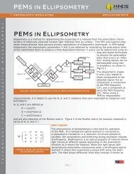
H I N D S I N S T R U M E N T S, I N C.P E MTMAPPLICATIONSNEWS FOR USERSOF PHOTOELASTICMODULATORSWINTER 1997/98ABOUT THE SCIENTISTCurrently Professor of Physics at TrinityCollege (Hartford CT), Dr. Silvermanhas held a number of distinguished appointmentsat universities throughout theworld, including the Joliot Chair of Physicsat the Ecole Superieure de Physique etChemie in Paris, the institution at whichthe earliest version photoelastic modulatorwas invented.Physics has been a lifelong passion,although Silverman became a professionalphysicist in a somewhat circuitous way,having first undertaken research in medicineand microbiology, and then later inorganic and physical chemistry. He earnedhis Ph.D. in physics from Harvard University.“I do not in the least regret the timethat I spent engaged in other fields,” hesays, “for these experiences have enrichedmy knowledge of the behavior andproperties of matter and helped me becomeoverall a more capable scientist.”“Nominally an atomic physicist, I havehad little inclination during my career tobecome a specialist, but rather have followedwherever my curiosity led. 1 Thus, Ihave been engaged in both ‘serious’ research(of a kind likely to attract fundingfrom research agencies) as well as purely‘entertaining’ research like the study ofcounter-intuitive physics toys and gadgets.”Such gadgets include the “vortextube” (a kind of Maxwell Demon <strong>with</strong> nomoving parts that blows hot air out of one(Continued on page 5)<strong>Seeing</strong> <strong>Through</strong> <strong>Foggy</strong> <strong>Media</strong><strong>with</strong> <strong>Phase</strong>-Modulated LightMark Silverman, Ph.D.Professor of PhysicsTrinity CollegeAnyone who has ever held a glass of milk up to the light realises how difficult it isto see through a turbid or cloudy medium. The problem is not that the milk appreciablyabsorbs light (like India ink, for example). Rather, the fat globules in the milk scatter lightnumerous times so that there is virtually no correlation in direction between enteringand emerging light rays. To see an object clearly through a surrounding medium, theviewer must receive light that has passed directly from the object to his eyes orinstruments <strong>with</strong>out diffusive scattering.Although few people need to peer through a glass of milk, there are many naturallyoccuring turbid media (fog, clouds, aerosols, seawater, skin, internal tissue, blood...)which are critical to a wide range of scientific, technological, and medical applications.For example, one outstanding problem of clinical medicine is the noninvasive detectionof subcutaneous malignancies <strong>with</strong>out the use of tissue-damaging ionizing radiation.At an altogether different scale of operation, remote monitoring of soil conditions andthe health of arboreal canopies often require remote sensing through a turbidatmosphere. Indeed, the problem of visual penetration of light-scattering media is ofsuch pressing importance that several international symposia have been devoted to itover the past year alone.One approach which I have developed entails the use of phase-modulated light todelineate targets embedded in optically dense turbid media and entirely hidden fromdirect viewing by ambient illumination. 1,2 The guiding principle of these experiments, forwhich the <strong>Hinds</strong> PEM-90 is a seminal component, is to detect nearly instantaneouslythe difference in scattering of two orthogonal states of linear or circular polarization. IfFigure 1: Experimental configurationfor polarimetric imaging. Light from alaser (L) passes a chopper (C),polariser (P), and thePEM; it is scattered byboth the turbid medium andembedded target of the sample (S).The scattered light is synchronouslydetected by a photomultiplier (D) andlock-in amplifiers (LA1 and LA2).
the linear or circular intensity difference (LID or CID) of lightreturned by the embedded object differs from that scattered bythe surrounding turbid medium, then scanning a light sourceacross the sample will yield an intensity profile that varies incorrespondence <strong>with</strong> structural features of the target. Figure 1shows a schematic diagram of the configuration for one set ofexperiments.Light from a helium-neon laser (λ = 544 nm) is mechanicallychopped, polarized vertically (<strong>with</strong> respect to the optical bench),and phase-modulated <strong>with</strong> a <strong>Hinds</strong> PEM. After scattering from aturbid sample consisting of an optically dense suspension ofmicron-sized latex particles, the light is synchronously detectedby means of two lock-in amplifiers that yield the dc photocurrentI(0) (effectively the signal at the low chopping frequency), thecomponent I(f) at the modulation frequency f ~ 50 kHz, and thecomponent I(2f) at the first harmonic. Analysis of the scatteringconfiguration shows that the signal I(f) is proportional to the CIDI(f) = KJ 1(ϕ o m )(J LCP -J RCP )(1a)(where J LCPand J RCPare the light fluxes corresponding to left andright circular polarizations), and the signal I(2f) is proportional tothe LIDI(2f) = KJ 2(ϕ o m )(J σ -J π )(1b)(in which linear polarizations σ, π are respectively perpendicularto, and parallel to, the scattering plane defined by the incident andscattering wave vectors). In the above equations, K is a commoninstrumental factor and J 1(ϕ o), J m 2 (ϕo ) are Bessel functions of themmodulation amplitude ϕ o = 2.405 radians. This choice of modulationamplitude, equal to the first zero of the Bessel function J 0m,strikes an excellent compromise between optimization of thesignal and simplification of the theoretical analysis.Why should polarimetric imaging work? After all, multiplescattering not only randomizes the direction of light propagation,Figure 2: [Left] Slotted target and [Right] horizontal scans of I(0) and I(2f) for an optically dense(2.8 x 10 -3 g/cm 3 ) suspension of 1 µm diameter latex particles.but also depolarizes light to an extent dependent on the numberof scattering interactions. Depending on wavelength and particlesize, nearly complete depolarization can result after roughly10 collisions – and yet polarimetric imaging has renderedobjects visible in media <strong>with</strong> optical densities well in excess of100. The optical density δ, defined as the product of the numberof particles per volume (N), the collision cross section (σ), andsample thickness (l), is effectively the mean number of collisionsundergone by a photon in the medium. Nevertheless, in thepassage of light through a turbid medium, there are alwaysphotons that have suffered only a few collisions rather than the(much larger) average number. The light that is scattered leastis depolarized least and, as pointed out above, constitute therays that give sharp images. Moreover, since multiple lightscattering from suspended particles is often much less sensitiveto polarization than is scattering from macroscopic objects, thediffusive contribution from the particles tends to cancel in theLID and CID, thereby leading to enhanced visibility.An example of polarimetric imaging <strong>with</strong> backscattered lightin shown in Figure 2 for the case of a target consisting of anopaque mask <strong>with</strong> periodic slots of width ~2 mm and separation~3 mm superposed on a reflective metallic base. In the companionframe one sees the results of a horizontal pointwise scan ofphotocurrents I(0) and I(2f) when the target was immersed in thecenter of a 1 cm thick suspension of 1 µm diameter particles <strong>with</strong>an optical density δ ~ 125. The peaks of I(0) correspond to thecenters of the slots where the reflectance is greatest. Bycontrast, the I(2f) scan attains maximum values (both positiveand negative) near the maximum slopes of the I(0) scan – thatis, at the edges of the slots. Thus the LID (and the CID as well)of a target <strong>with</strong> sharp edges is particularly sensitive to thelocation of these boundaries.It is worth noting that the dc signal I(0), which shows targetstructure <strong>with</strong> a visibility of ~13%, does not correspond to whatone sees by direct viewing in ambientlighting. To the unaided eyethe sample appears milky whiteand reveals no presence at all ofthe embedded object. The I(2f)scan, however, renders the topographyof the object <strong>with</strong> 63%contrast.Another example of polarimetricimaging is shown in Figure 3 forthe case of a target consisting oftwo orthogonally oriented segmentsof grooves of width
Figure 3: [Left] Grooved target and [Right] horizontal scans of I(0) and I(2f) for an optically dense(1.4 x 10 -3 g/cm 3 ) suspension of 1 µm diameter latex particles.molecules that cannot be superposedon their mirror images.Chiral (or left-right) asymmetryhas profound consequences inboth the physical and biologicalsciences. It is, for example, thehallmark of the living state; allsugars and amino acids of biologicalorigin display a particularhandedness, rather than a 50-50mix of both isomeric forms.Early in the 19th century theFrench physicist Augustin Fresnelwas the first to realize that LCPand RCP light have different phasevelocities in a chiral medium andthence to separate an unpolarizedlight beam into two circularlypolarized components by differentialrefraction through a seriesof chiral prisms. Nearly 175 years later my colleagues and I werethe first to observe the companion phenomenon of differentialreflection of LCP and RCP light from a naturally optically activematerial. 4 In this research, which opened up new possibilities forinvestigating chiral materials, the PEM was again an indispensablecomponent, for it provided the means to measure thedifferential circular reflection in effectively a single step. So smallis the difference in LCP and RCP refractive indices (a few partsin ten million in our experiments), that one could never hope toobserve the difference in specular reflection of separate circularlypolarized beams.It was, in fact, the extension of these chiral studies onhomogeneous materials into the domain of turbid media that ledme to pursue methods of polarimetric imaging. Motivated in partby the challenge of finding a noninvasive way to monitor bloodglucose levels (a procedure critical to patients <strong>with</strong> diabetes), mylaboratory undertook to measure optical rotatory power in opticallydense chiral media. Using a <strong>Hinds</strong> PEM in a configurationsimilar to that of Figure 1, but <strong>with</strong> a rotatable linear polarizer andprecision angular micrometer before the photomultiplier detector,we determined the optical rotation for different concentrationsof aqueous glucose solution and achiral scatterers by nulling thephotocurrent I(2f). 5 The results were highly surprising.We expected, in accordance <strong>with</strong> prevailing views, thatmultiple scattering would randomize the polarization of theincident probe beam and lead to vanishingly small opticalrotations for highly turbid media. Instead we found relativelylarge optical rotations – in some cases considerably larger thanthat of the corresponding particle-free, transparent, homogeneousglucose solution. The explanation of this unusual outcomeis attributable in part to two effects: (a) multiple scatteringlengthens the total optical pathlength through the medium, and(b) for a given number of collisional interactions, circularlypolarized light is depolarized to a lesser extent than is linearlypolarized light.in the same kind of suspension as before (but <strong>with</strong> one half theoptical density). The eye again sees nothing but a white opacity.In this case the dc scan, which is essentially flat across the objectand drops off at the edges, also shows no structural featuresbeyond a small dip where the two segments are joined. The I(2f)scan, however, resembles a square pulse waveform <strong>with</strong> apositive LID on the left half of the figure (0-8 mm) and a negativeLID on the right half (8-16 mm). This is precisely what one wouldexpect [see Eq. (1b)] for a conducting grating <strong>with</strong> groovesoriented vertically on the left half (thereby backscattering apreponderance of σ-polarized light) and horizontally on the righthalf (leading to a preponderance of π-polarized light).The preceding experiments, along <strong>with</strong> others carried out inmy laboratory, help define the conditions under which polarimetricimaging <strong>with</strong>in turbid media can be implemented successfully. 3They illustrate, for example, the significance of particle size (aswell as concentration) as gauged by the size parameter ζ = 2πna/λ, where n is the relative refractive index of the medium and a isa characteristic size parameter (e.g. the radius of a sphericalparticle). Very small particles (ζ
<strong>Seeing</strong> <strong>Through</strong> <strong>Foggy</strong> <strong>Media</strong>(continued from page 3)The observation of optical rotation of backscattered lightwas especially interesting, for it indicated that photons had ineffect freely (i.e. <strong>with</strong>out scattering) traversed the distance fromthe interior of the turbid medium to the photodetector. This is, infact, what one would have expected for large particles scatteringpredominantly in the forward direction. Had the light beenscattered backward and forward multiple times before reachingthe detector, the optical rotation would have been largelyrandomized. The light-scattering conditions revealed by ourstudies of optical activity in turbid chiral media are preciselythose that are conducive to polarimetric imaging by backscattering.This is a felicitous outcome, for the backscatteringconfiguration is often the most convenient for materials analysisand medical diagnostics.Experiments like those described above show the feasibilityof using phase-modulated light for physico-chemical analysisand object delineation in well-defined optically dense media.There remains still the task of ascertaining how well suchmethods work as practical tools to investigate naturally occuringturbid media of environmental and biomedical significance. Ifpast experience is any guide, nature has not exhausted herstore of intriguing problems surrounding the behavior of lightand matter.REFERENCES1. M. P. Silverman and Wayne Strange, “Light Scatteringfrom Optically Active and Inactive Turbid <strong>Media</strong>,” Opticsand Imaging in the Information Age (Society for ImagingScience and Technology, Springfield VA, 1996) 173-180.2. M. P. Silverman and Wayne Strange, “Object Delineation<strong>with</strong>in Turbid <strong>Media</strong> by Backscattering of <strong>Phase</strong>-ModulatedLight,” Optics Communications 144 (1997) 7-11.3. M. P. Silverman, Waves and Grains: Reflections on Lightand Learning (Princeton Univ. Press, Princeton NJ, 1998)to be published.4. M. P. Silverman, J. Badoz, and B. Briat, “Chiral Reflectionfrom a Naturally Optically Active Medium,” Optics Letters17 (1992) 886-888.5. M. P. Silverman, W. Strange, J. Badoz, and I. A. Vitkin,“Enhanced Optical Rotation and Diminished Depolarizationin Diffusive Scattering from a Chiral Liquid,” Optics Communications132 (1996) 410-416.NEW PRODUCTVacuum Chamberfor the I/CF50 PEMThe PEM-90 photoelastic modulator is well suited forexperiments that measure circular dichroism (CD), the measurementof the differential absorption between left and rightcircularly polarized light components. However, because of theabsorption of ultraviolet radiation in air, a vacuum system isneeded to make CD measurements in the ultraviolet spectralrange below about 180 nm. In the past we have worked closely<strong>with</strong> our UV CD customers to design custom vacuum chambersto house the PEM’s optical head. However, following a newphase of product development, we now offer a standard vacuumchamber enclosure.Our standard vacuum chamber is constructed from remelt304 stainless steel. It is a four way cross configuration whichuses 2 3/4” O. D. flanges <strong>with</strong> 1 3/8” I. D. tubes. This is theminimum size that will accommodate models I/CF50 and I/LF50modulators. Inside the cross chamber, a specially designed tray(patent pending) supports the optical assembly so that itsposition is secure and normal to the light beam.Conical reducers will allow our standard vacuum chamberdesign to interface <strong>with</strong> both larger and smaller flanges. Alsowindows and extenders are available that can be used to locatediagnostic instrumentation either <strong>with</strong>in or outside the vacuum.<strong>Hinds</strong> engineers can assist in the design of a complete vacuumsystem.UPCOMING EVENTSOur schedule of technical conferences and exhibits forthe first half of 1998 includes:• Pittcon, March 1-6, New Orleans• CLEO ’98, May 3-8, San FranciscoLook for the <strong>Hinds</strong> <strong>Instruments</strong> exhibit at these venues.4 HINDS INSTRUMENTS, INC.
About the Scientist (from page 1)end and cold air out the other) and the Voice of the Dragon (arotating tube that generates an eerie and puzzling spectrum ofsounds). “Ironically – or perhaps not – it is the latter category ofresearch that often presents some of the most difficult andchallenging problems,” Silverman adds.One subject that has long held his attention is that ofquantum interference – those curious, nonintuitive processesfor which no imaginable classical mechanisms can be given. 2During the 1980s he served as Visiting Chief Researcher at theHitachi Advanced Research Laboratory (then near Tokyo) todevelop new types of electron interferometry experiments partlyfor practical applications, but principally to probe hitherto untestedpredictions of quantum mechanics. He has also beenfascinated by light, studying problems spanning the full range ofphysical optics including reflection, refraction, diffraction, interference,polarization, and light scatterings. 3 Recent work, apartfrom the studies of chiral media discussed briefly in the PEMarticle, include the investigation of methods of lensless imagingand optical information processing.“Most of the physics I know I did not learn in school,”Silverman says, “but acquired through the process of seekinganswers to questions that interested me. That is also the wayyoung children acquire knowledge about their world. As ateacher, as well as a research scientist, I believe that anyeducational system that does not allow for self-directed inquiry<strong>with</strong>in its methodology cannot enlist effectively the innate driveof human beings to learn, and may well serve to suppress thatdrive.”Accordingly, in his college and university level classes,Silverman tries to stimulate students by engaging them inindependent project work. “I have written and lectured extensivelyabout the motivations and implementation of ‘Self-DirectedLearning’ at all levels of education. 4 At home, my wife and I arethe principal teachers of our own children – a serious responsibilitywe have undertaken from their elementary school yearsthrough high school.” He concludes, “Teaching our own childrenhas been a challenging but rewarding experience-and I havelearned at least as much from them as they have from me.”NOTES1 Silverman provides a nontechnical account of some of thediverse problems he has studied over the past 30 years ina recent book, And Yet It Moves: Strange Systems andSubtle Questions in Physics (Cambridge Univ. Press,1993).2 M.P. Silverman, More Than One Mystery: Explorations inQuantum Interference (Springer, 1995).3 Silverman’s forthcoming book, Waves and Grains: Reflectionson Light and Learning (Princeton Univ. Press, 1998),describes his work in optics.4 M.P. Silverman, “Self-Directed Learning: A Heretical Experimentin Teaching Physics,” American Journal ofPhysics 63 (1995) 495-508.PEM LITERATURE AVAILABLE FROM HINDSRECENT PUBLICATIONS1. A Polarization Modulator Using the Photoelastic Effect(Wang, Sperling 1997)2. Measurement of Waveplate Retardation Using a PhotoelasticModulator (Oakberg, 1997)3. Introduction to Polarization Modulation FT/IR Spectroscopy(Wang, 1997)4. Measurement of Low-Level Strain Retardation in OpticalMaterials (Oakberg, 1997)OTHER PUBLISHED ARTICLES1. Measurement of Low-Level Strain Birefringence in OpticalElements Using a Photoelastic Modulator (Oakberg, 1996)2. Photoelastic Modulator Based Vibration Circular Dichroism(Wang, 1996)3. Infrared Reflection-Absorption Spectroscopy Using ThePhotoelastic Modulator (Wang, 1997)4. Modulated Interference Effects: Use of PhotoelasticModulators <strong>with</strong> Lasers (Oakberg, 1995)5. Polarized Light and Its Interaction <strong>with</strong> Modulation Devices(Kemp,1987)APPLICATION NOTES1. Linear and Circular Dichroism2. Linear Birefringence and Optical Rotation3. Light Intensity Modulation Using a PEM4. Stokes Polarimetry5. Detecting the Ratio of I AC/I AVE6. Characteristics of PEM Optical Materials7. Use of PEMs <strong>with</strong> Lasers8. Calibration9. PEM Retardation Versus Angle of Incidence10. Spatial Variation of Modulation Efficiency in PhotoelasticModulators11. Useful Aperture of PEMs12. Selected References for Ellipsometry13. Optical Head, Electronic Head and Controller Dimensions14. Cleaning and Handling Suggestions for Coated OpticsPRODUCT DATA BULLETINS1. PEM-90 Photoelastic Modulators Brochure2. PEM-90 Photoelastic Modulator Systems3. PEM-90 Head Assemblies4. PEM-90 Controller5. Detector/Preamplifiers & Signal Conditioning UnitFor a copy of any of these publications or for furtherinformation, contact: <strong>Hinds</strong> <strong>Instruments</strong>, Inc.3175 NW Aloclek Dr. • Hillsboro, OR 97124Phone: (503) 690-2000 • Fax: (503) 690-3000Toll-free: 1 800 688-4463 • Email: info@hindspem.comWINTER 1997/98 5
3175 NW Aloclek DriveHillsboro, OR 97124 USABULK RATEUS POSTAGE PAIDHillsboro, ORPermit No. 76Address correction requested.INSIDE PEM• <strong>Seeing</strong> <strong>Through</strong> Turbid <strong>Media</strong><strong>with</strong> <strong>Phase</strong>-Modulated Light• New Vacuum Chamberfor the I/CF50 PEM© 1997, <strong>Hinds</strong> <strong>Instruments</strong>, Inc.Printed in USA. 5M/12-97