A PEM-based Stokes Polarimeter for Tokamak ... - Hinds Instruments
A PEM-based Stokes Polarimeter for Tokamak ... - Hinds Instruments
A PEM-based Stokes Polarimeter for Tokamak ... - Hinds Instruments

You also want an ePaper? Increase the reach of your titles
YUMPU automatically turns print PDFs into web optimized ePapers that Google loves.
HINDS INSTRUMENTS, INC.SUMMER 2002<strong>PEM</strong>TMAPPLICATIONSNEWS FOR USERSOF PHOTOELASTICMODULATORSTOKAMAK PLASMA DIAGNOSTICSA <strong>PEM</strong>-<strong>based</strong> <strong>Stokes</strong> <strong>Polarimeter</strong> <strong>for</strong><strong>Tokamak</strong> Plasma DiagnosticsABOUT THE SCIENTISTSDr. Fred LevintonDr. Robert C. WolfNova Photonics, Inc.Max-Planck Institut für PlasmaphysikDr. Fred Levinton received his B.Sc. Degree inphysics from McGill University, Canada, and hisPh.D. in physics from Columbia University. Hedeveloped the motional Stark effect (MSE)diagnostic <strong>for</strong> measuring the magnetic field inhigh temperature plasmas which was implementedat the Princeton Plasma Physics Lab.Dr. Levinton received the American PhysicalSociety’s 1997 Award For Excellence In PlasmaPhysics Research <strong>for</strong> the concept and developmentof the MSE diagnostic. He is currently withNova Photonics, Inc.Robert C. Wolf received his Diploma from theUniversity of Aachen and his Ph.D. from theUniversity of Düsseldorf in 1993. In 1996 hebecame associated with the ASDEX Upgradetokamak, one of the magnetic confinementfusion devices of the Max-Planck-Institut fürPlasmaphysik in Garching, Germany, and theredeveloped the Motional Stark Effect polarimeter.At present he is working at the Joint EuropeanTorus tokamak, the world’s largest facility of itskind, as task <strong>for</strong>ce leader responsible <strong>for</strong> theprogram concerning improved confinementregimes. In September 2002 he will move toForschungszentrum Jülich to become one of thedirectors of the Institut für Plasmaphysik.A Most research tokamaks use only deuterium,a stable isotope of hydrogen. Future power-producing fusionreactors will likely use tritium as well as deuterium. As ofthe date of this article, the use of tritium has been testedonly at the TFTR tokamak at Princeton and the JET facility inCulham, U.K. .by Dr. Theodore C. Oakberg, Senior Applications Scientist<strong>Hinds</strong> <strong>Instruments</strong> photoelastic modulators (<strong>PEM</strong>s) have played an importantrole in nuclear fusion energy research. A <strong>Stokes</strong> polarimeter usinga special dual <strong>PEM</strong> system is used with “tokamak” plasma fusion reactors<strong>for</strong> determining characteristics of the magnetic field and the plasma.This technique is called “Motional Stark Effect Polarimetry” or the“MSE Diagnostic.”<strong>Tokamak</strong> Plasma Fusion ReactorsA “tokamak” is a device <strong>for</strong> containing a plasma (ionized gas) using a strongmagnetic field. Originally conceived by Soviet scientists Igor Tamm andAndrei Sakharov, it is today the most promising of several such magneticcontainment devices. The tokamak is the focus of an intense worldwide1ef<strong>for</strong>t to control nuclear fusion <strong>for</strong> electric power generation.The plasma (an ionized gas of the heavy hydrogen isotopes deuterium,2 3 AH , and, on rare occasions, tritium, H ) is enclosed in a vacuum chamber inthe shape of a torus (donut). The idea is to “contain” the plasma at the veryhigh temperatures required <strong>for</strong> nuclear fusion (about 100 million degreesC) using magnetic fields. One of these magnetic fields, the “toroidal” field,is produced by large current-carrying coils around the torus. The magneticflux from these coils is also toroidal in shape, and the field lines “fill” thetorus cavity (Figure 1a).(continued on page 2)Dual <strong>PEM</strong> Systems <strong>for</strong> PolarimetryPhotoelastic modulators have historically been used in polarimetry. Whenthe <strong>PEM</strong> is used as a polarization analyzer, it is generally useful to use a dual<strong>PEM</strong> system. A dual <strong>PEM</strong> system can characterize any polarization state byobtaining all four <strong>Stokes</strong> vectors simultaneously. By using a dual <strong>PEM</strong>system, the unparalleled high sensitivity, spectral range and stability ofphotoelastic modulators (<strong>PEM</strong>s) can be applied to study polarization.One of the first uses <strong>for</strong> the <strong>PEM</strong> was astronomical polarimetry.Applications can also be found in <strong>Stokes</strong> polarimetry and Optical Rotation.Other polarization analysis <strong>PEM</strong> applications include laser lightcharacterization and magnetic field diagnostics in tokamaks throughoutthe world. (continued on page 5)
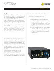
Novel system design detailsThere are a number of unique design features associatedwith this and other tokamak <strong>PEM</strong> polarimeter systems.1 Protecting the <strong>PEM</strong> electronic heads from strongmagnetic fields.The <strong>PEM</strong> electronic heads are susceptible to strongmagnetic fields. It is there<strong>for</strong>e necessary to locate theelectronic heads some distance away from the dual opticalDhead, or magnetically shield the electronic heads or both.The coaxial head-to-head cables are 15 meters long <strong>for</strong> theASDEX Upgrade tokamak installation.2 Optical signal transmission via optical fibersOptical fiber bundles are used to conduct the lightfrom the <strong>PEM</strong> assembly to the individual detectors(photomultiplier tubes or PMTs). The intensity modulatedlight signals are carried to the control room where thedetectors and associated electronics are located. The polarizationof the light is lost in the fibers, but this is an advantage,since the type of PMTs being used are polarizationsensitive.3 Fine tuning of wavelength selectionAn aspheric lens collimates the light coming from theend of the fiber bundle which passes through an interferencefilter and another lens to the photomultiplier tube. Eachinterference filter has a spectral bandwidth of about 0.2 to0.3 nm. The center wavelength of each filter is “tuned” byvarying the filter temperature and/or tilting the filter. Eachchannel has a single PMT which is connected to a preamplifierwith a gain of 10 volt/amp. Each pre-amplifier is5then connected to two lock-in amplifiers, one at 40 kHz andthe other at 46 kHz (twice the oscillation frequencies of the<strong>PEM</strong>s).4 Real-time data analysisThe output of each lock-in amplifier goes to an A-D converter.Data is sampled at a rate of 1 kHz. At the present,ASDEX Upgrade data is reduced at the end of the run. Itwould be possible to per<strong>for</strong>m real-time data analysis and usethe in<strong>for</strong>mation in a feedback loop to control the reactor.This may be tried with the ASDEX Upgrade in the future.B0 rInsidewalltorusvacuumchamberOutsidewalltoroidalfieldstrengthpoloidalfieldstrengthFigure 4. Relative intensities of toroidal and poloidalmagnetic fields, vs radial position.Summary<strong>Stokes</strong> polarimeters using a dual <strong>PEM</strong> are an important partof the diagnostics of tokamak plasmas in installationsaround the world. <strong>Hinds</strong> <strong>Instruments</strong> employees are proudof the role our product plays in nuclear fusion research. Weat <strong>Hinds</strong> <strong>Instruments</strong> are very grateful to Dr. Fred Levinton ofFusion Physics <strong>for</strong> developing this application of thephotoelastic modulator and <strong>for</strong> his assistance with thisarticle. I am personally grateful to Dr. Robert Wolf <strong>for</strong> hisassistance in helping me understand the operation of thetokamak and the details of the Motional Stark Effectpolarimeter and <strong>for</strong> his assistance in preparing this article.Bibliography1. Herman, Robin, “Fusion: The Search <strong>for</strong> Endless Energy”, CambridgeUniversity Press, 1990.2. F.M. Levinton, et.al., “Magnetic field pitch angle diagnostic using themotional Stark effect”, (invited), Rev. Sci. Instrum. 61 2914 (1990).3. F.M. Levinton, “The multichannel motional Stark effect diagnostic onTFTR,” Rev. Sci. Inst. 63 5157 (1992).4. D. Wroblewski and L.L. Lao, “Polarimetry of motional Stark effect anddetermination of current profiles in DIII-D”, (invited) Rev. Sci. Instrum.63 5140 (1992).5. F.M. Levinton, et.al., “Improved Confinement with Reversed MagneticShear in TFTR”, Phys. Rev. Lett 75 4417 (1995).<strong>Hinds</strong> <strong>Instruments</strong> Teams with InternationalSEMATECH to Develop an Instrument thatCharacterizes Birefringence in Calcium Fluoride<strong>for</strong> 157 nm MicrolithographyIn recent years, optical lithography has continued itstransition to shorter wavelengths in order to produce moreadvanced microchips. The next generation of optical lithographysystems will use F2Excimer lasers operating at157 nm. Due to its unique optical properties and readiness<strong>for</strong> large-scale production, calcium fluoride (CaF 2) is the onlypractical optical material available <strong>for</strong> use in stepper andscanner lenses at this wavelength. Consequently, linear birefringencein CaF2components has emerged as an importantquality parameter <strong>for</strong> the optical lithography industry.In May 2001, as part of a project with InternationalSEMATECH, researchers at the National Institute ofStandards and Technology (NIST) reported intrinsicbirefringence in CaF2that affects lens design and images atthe wafer level in 157 nm microlithography systems. Thisnews came as an unwelcome surprise to the opticallithography industry. Prior to this discovery it was commonlyassumed, incorrectly, that CaF 2, belonging to the cubiccrystal group, was an “isotropic” material.(continued on page 6)C The magnitude of the Doppler shift in wavelength is proportional to the componentof the particle velocity along the direction of the line of sight.D<strong>Hinds</strong> <strong>Instruments</strong> recommends that the electronic heads be located in a magneticfield no stronger than 100 Gauss or 0.01 Tesla.SUMMER 2002 4
The II/ZS37-50 has ZnSe as the optical material. Thisprovides a transmission range from 514nm to 18µm. This<strong>PEM</strong> has applications in the infrared region of the lightspectrum. It is used to analyze both broadband light sourcesand infrared lasers, such as the CO2laser.Like all <strong>Hinds</strong> <strong>PEM</strong>s, these systems provide the uniquebenefit of a wide acceptance angle (> ± 20 degrees), a goodtransmission <strong>for</strong> a wide wavelength range, high powerhandling capabilities and a high polarization sensitivity. Thetable below compares the technical specifications <strong>for</strong> all ofthe dual <strong>PEM</strong> systems.Dual <strong>PEM</strong> Systems <strong>for</strong> Polarimetry(continued from page 1)Dual <strong>PEM</strong> Models<strong>Hinds</strong> <strong>Instruments</strong> has five standard dual <strong>PEM</strong> systems <strong>for</strong>applications that require different useful apertures andmeasurements in different spectral regions. The dual <strong>PEM</strong>models are:• I/FS50-55 • II/FS42-47• I/FS47-50 • II/ZS37-50 • II/FS20-23The I/FS50-55 and the I/FS47-50 systems use the series I<strong>PEM</strong> with fused silica as the optical material. The series l <strong>PEM</strong>has a rectangular shaped optic that has a useful aperturethat is limited by the height of the optic. These small systemsare useful when the light source has a small beam diameter.Most of the dual <strong>PEM</strong> systems utilize the series II <strong>PEM</strong>s,which contain octagonal shaped optical elements. Theseries II <strong>PEM</strong>s meet higher requirements <strong>for</strong> magnitude ofmodulation and offer symmetrical distribution of <strong>PEM</strong>retardation over a larger aperture range.The II/FS20-23 and the II/FS42-47 systems also employhigh quality fused silica as the optical material and have atransmission range of 170nm to 2.6µm. Both models areuseful <strong>for</strong> quarter and half wave retardation in the UV,visible and near IR light spectral regions. Of the two models,the II/FS20-23 system has the benefit of a larger aperture.This is especially useful if the light source has a large beamdiameter or more than one light source is to beimaged through the optic. The II/FS42-47, on the other hand,provides a more compact optical head configuration.Applications <strong>for</strong> Dual <strong>PEM</strong> SystemsPolarization Analysis and <strong>Stokes</strong> PolarimetryThe most common use <strong>for</strong> a dual <strong>PEM</strong> system is to analyzethe polarization state of a light source. There are differentways to represent light polarization. One of these is to use<strong>Stokes</strong> vectors or parameters (I, Q, U and V). Using the 1f and2f reference signals from each of the controllers, a dual <strong>PEM</strong>system is able to provide all four of the <strong>Stokes</strong> para-meterssimultaneously. Any light polarization can be charac-terizedby using these four parameters. For more in<strong>for</strong>ma-tion,please see the <strong>Stokes</strong> Polarimetry application note on ourwebsite.Astronomical PolarimetryOne of the first uses of the photoelastic modulator wasastronomical polarimetry. Dr. James Kemp, late Professor ofPhysics at the University of Oregon, used <strong>PEM</strong>s to study thepolarization of light from nearby stars and features on thesun, such as sunspots. The four <strong>Stokes</strong> parameters (I, Q, U, V)give a complete description of the polarization state of thesestellar light sources. For more in<strong>for</strong>mation on this application,please refer to <strong>Hinds</strong> <strong>Instruments</strong>’ <strong>PEM</strong> Newsletter #1on our website.<strong>Tokamak</strong><strong>Hinds</strong> <strong>Instruments</strong> manufactures a dual <strong>PEM</strong> system specificallydesigned <strong>for</strong> Motional Stark Effect (MSE) diagnosticpolarimeters associated with tokamaks. A detailed descriptionof this application is the feature article of this newsletter.Dual <strong>PEM</strong> systems provide the capability to make realtime polarization analysis measurements. These systems areavailable in a wide variety of materials and configurations tosupport many diverse applications. A <strong>Hinds</strong> sales engineer orapplication scientist will be glad to explain any of theseoptions. Please contact us with any questions or comments.Technical Specifications <strong>for</strong> Dual <strong>PEM</strong>-90 SystemsModel Optical Nominal Spectral Range Range of Range of UsefulMaterial frequencies λ/4 Retardation λ/2 Retardation apertureII/ZS37-50 ZnSe 37 - 50kHz 550nm - 18µm 550nm - 18µm 550nm - 10µm 13mm*II/FS20-23 Fused Silica 20 - 23kHz 170nm - 2.6µm 170nm - 2.6µm 170nm - 2.5µm 45mm*II/FS42-47 Fused Silica 42 - 47kHz 170nm - 2.6µm 170nm - 2.6µm 170nm - 2.6µm 23mm*I/FS50-55 Fused Silica 50 - 55kHz 170nm - 2.6µm 170nm - 2µm 170nm - 1µm 16mmI/FS47-50 Fused Silica 47 - 50kHz 170nm - 2.6µm 170nm - 2µm 170nm - 1µm 16mm*Useful aperture is defined as the area <strong>for</strong> which the average retardation is 90% of the retardation at the center. For more in<strong>for</strong>mation, please contact <strong>Hinds</strong> <strong>Instruments</strong>.SUMMER 2002 5
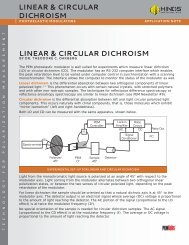
HINDS INSTRUMENTS,INC.3175 NW ALOCLEK DRIVEHILLSBORO, OR 97124 USABULK RATEUS POSTAGE PAIDHillsboro, ORPermit number 76PHONE: 503/690.2000FAX: 503/690.3000TOLL FREE: 1.800/68 8.4 4 6 3EMAIL: info@hindspem.comWEB SITES: www.hindspem.comwww.exicor.comReturn service requestedINSIDE <strong>PEM</strong><strong>PEM</strong>-<strong>based</strong> <strong>Stokes</strong> <strong>Polarimeter</strong>Dual <strong>PEM</strong> SystemsHINDS Teams With SEMATECH©2002, <strong>Hinds</strong> <strong>Instruments</strong>, Inc.Printed in USA. BB/4M/07-02(continued from page 4)HINDSTeams WithSEMATECHFigure 5.IntrinsicBirefringenceof CaF2at157nmTo respond to this issue, <strong>Hinds</strong> has extended its corecompetency in low-level visible birefringence measurements todevelop a system to characterize birefringence in any opticalmaterial transparent at 193 nm or 157 nm. We were awarded acontract with SEMATECH to expedite the development of theDUV birefringence measurement system. They have tasked<strong>Hinds</strong> to provide the semiconductor industry with measurementmetrology <strong>for</strong> QC, as well as lab R&D use, <strong>for</strong> characterizing theinteraction between DUV light and CaF2in lithography imagingsystems.Data from a prototype DUV birefringence measurementsystem was reported at International SEMATECH’s 157nmTechnical Data Review this May in Dallas, TX. One of our seniorapplication scientists, Dr. Bob Wang, showed 2-D images as wellas contour maps which vividly displayed both the magnitudeand corresponding fast axis angle of residual and the recentlydiscovered intrinsic <strong>for</strong>m of birefringence in CaF2at 157 nm.An example is shown in Figure 5. This data represents the firstmultidimensional characterization of CaF 2’s birefringence at157 nm resulting from our collaboration with SEMATECH.Dr. Wang’s preliminary findings, measured at different crystalorientations, confirmed high levels of intrinsic birefringence.Furthermore, the 2-D birefringence maps of the entire surfacesof CaF2cubic samples measured at the (110) orientationdemonstrated significant variation in birefringence, possiblydue to residual birefringence in those samples. Lower levels ofbirefringence, with significant variation in magnitude andangle, were also observed <strong>for</strong> the (001) orientation.One design solution that has been proposed to reducethe intrinsic birefringence at 157 nm is to couple lenses inthe imaging system at offsetting orientations. Dr. Wangdemonstrated the validity of this approach. He presented datafrom two stacked cubes that had the same orientation (110)with a resulting total mean birefringence of 54 nm. When oneof the cubes was rotated by 90°, the total birefringence wasdrastically reduced to below 1 nm/cm.<strong>Hinds</strong> is aggressively pursuing the development of a DUVbirefringence measurement system and has an engineeringmodel in development. A commercial system capable ofmeasuring samples as large as 400 mm diameter x 270 mm thickis scheduled to be available during the second half of 2002.6