Signal Conditioning Unit SCU-100 - Hinds Instruments
Signal Conditioning Unit SCU-100 - Hinds Instruments
Signal Conditioning Unit SCU-100 - Hinds Instruments

You also want an ePaper? Increase the reach of your titles
YUMPU automatically turns print PDFs into web optimized ePapers that Google loves.
<strong>Signal</strong> Processing<br />
<strong>SCU</strong>-<strong>100</strong><br />
PRODUCT BULLETIN<br />
Overview<br />
•••••••••••••••••••••••••••••••••••••••••••••••••••••••••••••••••••••••••••••••••••••••••<br />
The <strong>SCU</strong>-<strong>100</strong> <strong>Signal</strong> <strong>Conditioning</strong> <strong>Unit</strong> takes a composite<br />
input signal, splits the signal into its broadband AC and lowpass<br />
DC signals, amplifi es these signals, then applies the<br />
amplifi ed signals to AC and DC outputs.<br />
The AC output voltage can be determined using a lock-in<br />
amplifi er and a digital voltmeter and can be used to measure<br />
the DC output voltage. The ratio of the AC to DC voltage is<br />
a necessary computation for the measurement of linear and<br />
circular dichroism.<br />
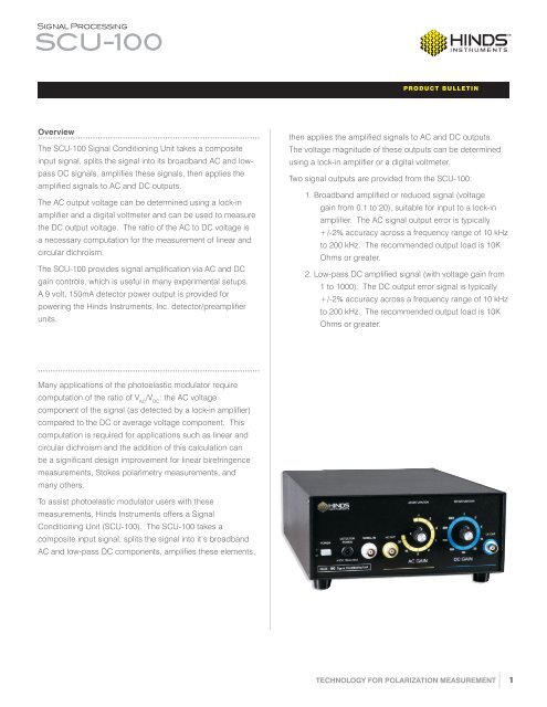
The <strong>SCU</strong>-<strong>100</strong> provides signal amplifi cation via AC and DC<br />
gain controls, which is useful in many experimental setups.<br />
A 9 volt, 150mA detector power output is provided for<br />
powering the <strong>Hinds</strong> <strong>Instruments</strong>, Inc. detector/preamplifi er<br />
units.<br />
then applies the amplifi ed signals to AC and DC outputs.<br />
The voltage magnitude of these outputs can be determined<br />
using a lock-in amplifi er or a digital voltmeter.<br />
Two signal outputs are provided from the <strong>SCU</strong>-<strong>100</strong>:<br />
1. Broadband amplifi ed or reduced signal (voltage<br />
gain from 0.1 to 20), suitable for input to a lock-in<br />
amplifi er. The AC signal output error is typically<br />
+/-2% accuracy across a frequency range of 10 kHz<br />
to 200 kHz. The recommended output load is 10K<br />
Ohms or greater.<br />
2. Low-pass DC amplifi ed signal (with voltage gain from<br />
1 to <strong>100</strong>0). The DC output error signal is typically<br />
+/-2% accuracy across a frequency range of 10 kHz<br />
to 200 kHz. The recommended output load is 10K<br />
Ohms or greater.<br />
•••••••••••••••••••••••••••••••••••••••••••••••••••••••••••••••••••••••••••••••••••••••••<br />
Many applications of the photoelastic modulator require<br />
computation of the ratio of V AC<br />
/V DC<br />
: the AC voltage<br />
component of the signal (as detected by a lock-in amplifi er)<br />
compared to the DC or average voltage component. This<br />
computation is required for applications such as linear and<br />
circular dichroism and the addition of this calculation can<br />
be a signifi cant design improvement for linear birefringence<br />
measurements, Stokes polarimetry measurements, and<br />
many others.<br />
To assist photoelastic modulator users with these<br />
measurements, <strong>Hinds</strong> <strong>Instruments</strong> offers a <strong>Signal</strong><br />
<strong>Conditioning</strong> <strong>Unit</strong> (<strong>SCU</strong>-<strong>100</strong>). The <strong>SCU</strong>-<strong>100</strong> takes a<br />
composite input signal, splits the signal into it’s broadband<br />
AC and low-pass DC components, amplifi es these elements,<br />
TECHNOLOGY FOR POLARIZATION MEASUREMENT 1
<strong>Signal</strong> Processing<br />
<strong>SCU</strong>-<strong>100</strong><br />
PRODUCT BULLETIN<br />
SPECIFICATIONS<br />
General<br />
Model Number <strong>SCU</strong>-<strong>100</strong>, P/N 020-2650-975<br />
Size<br />
Weight<br />
Power<br />
Power Fuses Rating<br />
8.37” W x 4.03” H x 12.86” D<br />
6 Lbs<br />
<strong>100</strong>-240 VAC (no switching required), 50-60 Hz, 27 Watts maximum<br />
(2) each, 1 Amp, Slo-Blo, 5 x 20 mm<br />
Composite <strong>Signal</strong> Input<br />
AC Component<br />
DC Component<br />
<strong>Signal</strong> Input Impedance<br />
10 VAC peak to peak, maximum<br />
0 to 10 VDC<br />
1 Megohm<br />
AC Output<br />
AC Gain Settings 0.1, 0.2, 0.5, 1, 2, 5, 10, 20<br />
AC Accuracy, typical<br />
AC Bandwidth<br />
AC Output Saturation Level<br />
Output Load Impedance, minimum<br />
AC <strong>Signal</strong> Input to Output Phase Shift<br />
DC Offset<br />
Cable Length<br />
+/- 2% throughout signal input, AC gain and AC bandwidth ranges and<br />
with AC Saturation LED OFF (1)<br />
10 KHz – 200 KHz<br />
1 VAC RMS<br />
10K Ohms<br />
18 degrees maximum, typical<br />
Less than 1 mV<br />
Specifi ed for a AC Output cable length not to exceed 3 meters<br />
DC Output<br />
DC Gain Settings 1, 2, 5, 10, 50, <strong>100</strong>, 200, 500, <strong>100</strong>0<br />
DC Accuracy, typical +/- 2% throughout DC gain ranges and with DC Saturation LED OFF (1)<br />
DC Output Saturation Level<br />
Output Load Impedance, minimum<br />
Cable Length<br />
10 VDC<br />
10K Ohms<br />
Specifi ed for a DC Output cable length not to exceed 3 meters<br />
Detector Power Output<br />
Detector Power Output Voltage Range<br />
Maximum Detector Power Output Current<br />
Detector Power Output Fuse Rating<br />
8.55 – 9.45 VDC<br />
150 mA<br />
(1) each, 0.200 Amp, Slo-Blo, 5 x 20 mm<br />
(1) This is a maximum value; accuracy is typically < 0.5%.<br />
<strong>Hinds</strong> <strong>Instruments</strong>, Inc | 7245 NW Evergreen Pkwy | Hillsboro, OR 97124 | USA<br />
T: 503.690.2000 | Fax: 503.690.3000 | sales@hindsinstruments.com<br />
Pemlabs is a Trademark of <strong>Hinds</strong> <strong>Instruments</strong>, Inc. Manufactured in USA<br />
© 2005, 2013 <strong>Hinds</strong> <strong>Instruments</strong>, Inc. All rights reserved. Printed in USA<br />
www.hindsintruments.com<br />
TECHNOLOGY FOR POLARIZATION MEASUREMENT 2