Selecting a PEM Optical Head - Hinds Instruments
Selecting a PEM Optical Head - Hinds Instruments
Selecting a PEM Optical Head - Hinds Instruments

You also want an ePaper? Increase the reach of your titles
YUMPU automatically turns print PDFs into web optimized ePapers that Google loves.
SELECTING A PHOTOELASTIC<br />
MODULATOR HEAD<br />
PHOTOELASTIC MODULATORS<br />
TECHNICAL NOTE<br />
T E C H N O L O G Y F O R P O L A R I Z A T I O N M E A S U R E M E N T<br />
SELECTING A PHOTOELASTIC<br />
MODULATOR HEAD<br />
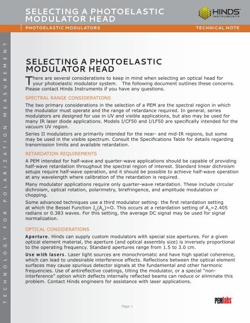
There are several considerations to keep in mind when selecting an optical head for<br />
your photoelastic modulator system. The following document outlines these concerns.<br />
Please contact <strong>Hinds</strong> <strong>Instruments</strong> if you have any questions.<br />
SPECTRAL RANGE CONSIDERATIONS<br />
The two primary considerations in the selection of a <strong>PEM</strong> are the spectral region in which<br />
the modulator must operate and the range of retardance required. In general, series<br />
modulators are designed for use in UV and visible applications, but also may be used for<br />
many IR laser diode applications. Models I/CF50 and I/LF50 are specifically intended for the<br />
vacuum UV region.<br />
Series II modulators are primarily intended for the near- and mid-IR regions, but some<br />
may be used in the visible spectrum. Consult the Specifications Table for details regarding<br />
transmission limits and available retardation.<br />
RETARDATION REQUIREMENTS<br />
A <strong>PEM</strong> intended for half-wave and quarter-wave applications should be capable of providing<br />
half-wave retardation throughout the spectral region of interest. Standard linear dichroism<br />
setups require half-wave operation, and it should be possible to achieve half-wave operation<br />
at any wavelength where calibration of the retardation is required.<br />
Many modulator applications require only quarter-wave retardation. These include circular<br />
dichroism, optical rotation, polarimetry, birefringence, and amplitude modulation or<br />
chopping.<br />
Some advanced techniques use a third modulator setting: the first retardation setting<br />
at which the Bessel Function J O<br />
(A O<br />
)=O. This occurs at a retardation setting of A O<br />
=2.405<br />
radians or 0.383 waves. For this setting, the average DC signal may be used for signal<br />
normalization.<br />
OPTICAL CONSIDERATIONS<br />
Aperture. <strong>Hinds</strong> can supply custom modulators with special size apertures. For a given<br />
optical element material, the aperture (and optical assembly size) is inversely proportional<br />
to the operating frequency. Standard apertures range from 1.5 to 3.0 cm.<br />
Use with lasers. Laser light sources are monochromatic and have high spatial coherence,<br />
which can lead to undesirable interference effects. Reflections between the optical element<br />
surfaces may cause spurious detector signals at the fundamental and other harmonic<br />
frequencies. Use of antireflective coatings, tilting the modulator, or a special “noninterference”<br />
option which deflects internally reflected beams can reduce or eliminate this<br />
problem. Contact <strong>Hinds</strong> engineers for assistance with laser applications.<br />
Page 1
SELECTING A PHOTOELASTIC<br />
MODULATOR HEAD<br />
PHOTOELASTIC MODULATORS<br />
TECHNICAL NOTE<br />
Antireflection coatings. Antireflection coatings may be used to increase the<br />
throughput of light through the modulator, to reduce interference effects, and to<br />
reduce the fraction of light which passes through the modulator at an undesired peak<br />
retardation. In particular, zinc selenide and silicon modulators benefit from antireflection<br />
coatings because of their high indices of refraction. Note: An antireflection coating will<br />
significantly reduce the usefulness of the modulator outside the spectral band of the<br />
coating.<br />
OPTICAL HEAD SPECIFICATIONS<br />
Model <strong>Optical</strong> Material Nominal<br />
Retardation Range<br />
Useful<br />
Frequency Quarter Wave Half Wave Aperture 1<br />
I/FS50 Fused Silica 50 kHz 170nm - 2μm 170nm - 1μm 16mm<br />
I/FS20 Fused Silica 20 KHz 170nm - 2μm 170nm - 1μm 22mm<br />
I/CF50 Calcium Fluoride 50 kHz 130nm - 2μm 130nm - 1μm 16mm<br />
II/FS20A Fused Silica 20 kHz 170nm - 2μm 170nm - 1μm 56mm<br />
II/FS20B Fused Silica 20 kHz 1.6μm - 2.6μm 800nm - 2.5μm 56mm<br />
II/FS42A Fused Silica 42 kHz 170nm - 2μm 170nm - 1μm 27mm<br />
II/FS42B Fused Silica 42 kHz 1.6μm - 2.6μm 800nm - 2.5μm 27mm<br />
II/FS47A Fused Silica 47 kHz 170nm - 2μm 170nm - 1μm 24mm<br />
II/FS47B Fused Silica 47 kHz 1.6μm - 2.6μm 800nm - 2.5μm 24mm<br />
II/FS84 Fused Silica 84 kHz 800nm - 2.5μm 400nm - 2.5μm 13mm<br />
II/IS42B Fused Silica 42 kHz 1.6μm - 3.5μm 800nm - 2.5μm 27mm<br />
II/IS84 Fused Silica 84 kHz 800nm - 3.5μm 400nm - 1.8μm 27mm<br />
II/CF57 Calcium Fluoride 57 kHz 2μm - 8.5μm 1μm - 5.5μm 23mm<br />
II/ZS37 Zinc Selenide 37 kHz 2μm - 18μm 1μm - 9μm 19mm<br />
II/ZS50 Zinc Selenide 50 kHz 2μm - 18μm 1μm - 10μm 14mm<br />
II/SI40 Silicon 40 kHz FIR - THz FIR - THz 36mm<br />
II/SI50 Silicon 50 Khz FIR - THz FIR - THz 29mm<br />
1<br />
For a full discussion, consult the Useful Aperture Technical Note<br />
<strong>Hinds</strong> <strong>Instruments</strong>, Inc / 7245 NW Evergreen Pkwy / Hillsboro, OR 97124 / USA<br />
T: 503.690.2000 / F: 503.690.3000 / sales@hindsinstruments.com / www.hindsinstruments.com<br />
<strong>PEM</strong>labs is a Trademark of <strong>Hinds</strong> <strong>Instruments</strong>, Inc. Manufactured in USA<br />
© 2005, 2009, 2010 <strong>Hinds</strong> <strong>Instruments</strong>, Inc. All rights reserved. Printed in USA<br />
Page 2