M140 Multifunction Calibrator / Tester - meatest.cz
M140 Multifunction Calibrator / Tester - meatest.cz
M140 Multifunction Calibrator / Tester - meatest.cz

Create successful ePaper yourself
Turn your PDF publications into a flip-book with our unique Google optimized e-Paper software.
MEATEST<br />
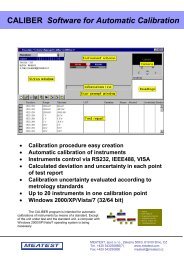
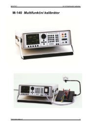
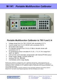
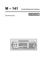
M-140 <strong>Multifunction</strong> <strong>Calibrator</strong><br />
• below the main data, an information about the shape type „Shape xxxxx“ is displayed.<br />
• below the main data, calculated effective value of the output signal is displayed.<br />
• for squarewave signals, set value of duty cycle „PWM= xx %“ is displayed.<br />
Simulation of resistance and capacitance<br />
The multifunction calibrator can simulate an exact value of resistance or capacitance. The outputs of the<br />
simulator are connected to Hi – Lo terminals and to AUXILIARY connector (pins 20, 21, 22, 23). 4W resistance<br />
is accessible only via cable adapter Opt. 70.<br />
Only two-wire wire connection is available on the front panel terminals Hi-Lo. Both two-wire and four-wire<br />
connection is possible only through AUXILIARY connector. The terminals SIMHI - SIMLI are current<br />
terminals and SIMHU - SIMLU are voltage sensing terminals. Cable adapter Option 70 or cable adapter Option<br />
140-41 must be used for four-wire connection. Type of cable adapter currently connected to the AUXILIARY<br />
connector, is displayed on the display. If Option 70 is connected, label CA 140-70 is displayed in the right side.<br />
If Option 140-4141 is connected, label CA 140-41 is displayed.<br />
Cable adapter Option 70 can be used for four-wire connecting of simulated resistance only. In compare with<br />
direct two-wire wire connection through output terminals Hi – Lo, accuracy of resistance is better with Option 70, see<br />
Technical data. If Cable adapter Option 70 is connected to the AUXILIARY connector, only resistance mode<br />
and resistance temperature simulation mode can be chosen.<br />
The resolution of resistance and capacitance depends on the set value and corresponds to 0.01 % of set value.<br />
Minimum set value is 0.01 Ω<br />
Resistance simulation range is 0 Ω to 50 MΩ.<br />
Capacitance simulation range is 0.9 nF to 50 µF.<br />
Control in the resistance and capacitance mode<br />
• press R-C button on the calibrator. The display shows the set resistance.<br />
• If you want to simulate a capacitance, press R-C button again. The display shows the set capacitance.<br />
• The display shows the following data:<br />
* main data of set resistance (capacitance)<br />
* relative deviation of resistance (capacitance)<br />
* uncertainty of set resistance (capacitance)<br />
* total value of resistance (capacitance) if non-zero deviation is set<br />
Operation manual v42<br />
23