M140 Multifunction Calibrator / Tester - meatest.cz
M140 Multifunction Calibrator / Tester - meatest.cz
M140 Multifunction Calibrator / Tester - meatest.cz

You also want an ePaper? Increase the reach of your titles
YUMPU automatically turns print PDFs into web optimized ePapers that Google loves.
MEATEST<br />
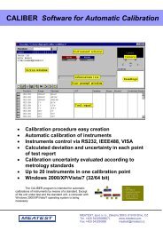
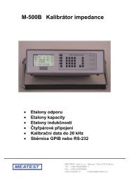
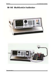
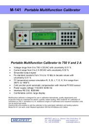
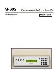
M-140 <strong>Multifunction</strong> <strong>Calibrator</strong><br />
Uncertainty calculation of set power<br />
Uncertainty of set power displayed on the Accuracy line of the display is calculated according to the following<br />
formula:<br />
for active power d P = √ ( dU 2 + dI 2 + dPF 2 + 0.03 2 ) [%]<br />
for reactive power d P = √ ( dU 2 + dI 2 + dPF* 2 + 0.03 2 ) [%]<br />
for apparent power d P = √ ( dU 2 + dI 2 + 0.03 2 ) [%]<br />
where dP is the uncertainty of set power [%]<br />
dU is the uncertainty of set voltage [%]<br />
dI is the uncertainty of set current [%]<br />
dPF is the uncertainty of set PF (cosϕ) [%]<br />
dPF* is the uncertainty of set sinϕ [%]<br />
Generation of frequency<br />
The multifunction calibrator can generate several different voltage shapes with exact frequency, amplitude and<br />
duty cycle. The output signal is present at BNC coaxial connector FREQ located at the front panel. The signal is<br />
not present at any other output terminal.<br />
There are two frequency generation modes. The first mode (PWM) allows the generation of squarewave output<br />
signal with calibrated amplitude, frequency and duty cycle. Frequency range is up to 10 kHz. The second mode<br />
(HF) also provides squarewave output signal with very steep rising edge, typically less than 3 ns.<br />
PWM mode<br />
Frequency range:<br />
Voltage range:<br />
Signal shapes:<br />
HF mode<br />
Frequency range:<br />
Voltage range:<br />
Signal shapes:<br />
0.1 Hz to 100 kHz<br />
1 mV to 10 Vpp<br />
squarewave, negative PWM NEG – symmetrical PWM SYM – positive<br />
PWM POS<br />
0.1 Hz to 20 MHz<br />
5 V pk-pk 0, -10, -20, -30 dB<br />
symmetrical squarewave<br />
PWM mode can be used to calibrate the input sensitivity of oscilloscopes at frequencies up to 10 kHz. HF mode<br />
can be used to calibrate the time base of oscilloscopes.<br />
To switch between the modes, keep pressing “F” direct mode button. The display includes the symbols for<br />
currently selected mode (PWM or HF).<br />
Control in the frequency mode<br />
• Press F direct mode button. The calibrator switches to PWM mode. If HF mode is desired, press F button<br />
once more. The main data on the display is the frequency.<br />
• The display shows the following data:<br />
* set frequency<br />
* relative deviation of frequency<br />
* signal amplitude (PWM mode ) or attenuation (HF mode)<br />
* duty cycle (PWM mode only)<br />
* signal shape: PWM NEG / POS / SYM (PWM mode only)<br />
Operation manual v42 31