M140 Multifunction Calibrator / Tester - meatest.cz
M140 Multifunction Calibrator / Tester - meatest.cz
M140 Multifunction Calibrator / Tester - meatest.cz

Create successful ePaper yourself
Turn your PDF publications into a flip-book with our unique Google optimized e-Paper software.
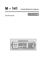
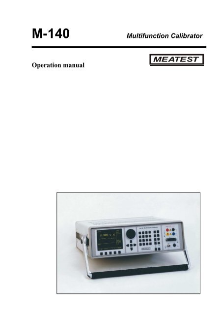
M-140 <strong>Multifunction</strong> <strong>Calibrator</strong><br />
Operation manual
MEATEST<br />
M-140 <strong>Multifunction</strong> <strong>Calibrator</strong><br />
Content<br />
Operation manual ...................................................................................................................... 1<br />
Basic Information ...................................................................................................................... 3<br />
Preparation for operation .......................................................................................................... 5<br />
Inspecting package contents, selecting the installation location .....................................................5<br />
Power-on ..............................................................................................................................................5<br />
Warm-up time .....................................................................................................................................5<br />
Replacement of fuse ............................................................................................................................6<br />
Safety precautions...............................................................................................................................6<br />
Description of controls .............................................................................................................. 7<br />
Front panel ..........................................................................................................................................7<br />
Rear panel .........................................................................................................................................13<br />
Control of the calibrator .......................................................................................................... 14<br />
Selection of function .........................................................................................................................14<br />
Setting the value of output signal ....................................................................................................14<br />
Setting relative deviation ..................................................................................................................16<br />
Change of value by factor of ten ......................................................................................................17<br />
Connection / disconnection of output terminals ............................................................................17<br />
Setting the frequency ........................................................................................................................18<br />
Generation of calibrated voltage .....................................................................................................19<br />
Generation of calibrated current ....................................................................................................21<br />
Generation of non-harmonic shapes ...............................................................................................22<br />
Simulation of resistance and capacitance .......................................................................................23<br />
Generation of electric power and energy ........................................................................................26<br />
Generation of frequency ..................................................................................................................31<br />
Simulation of temperature sensors..................................................................................................34<br />
Multimeter ................................................................................................................................ 38<br />
Basic menu ........................................................................................................................................38<br />
Function selection .............................................................................................................................39<br />
Setting the measurement range .......................................................................................................39<br />
Units of measurement .......................................................................................................................40<br />
Use of calculation formula ...............................................................................................................40<br />
Setting function parameters.............................................................................................................41<br />
Start of measurement .......................................................................................................................42<br />
Zero function .....................................................................................................................................42<br />
Simultaneous functions ....................................................................................................................44<br />
Operation manual v42 1
M-140 <strong>Multifunction</strong> <strong>Calibrator</strong> MEATEST<br />
<strong>Tester</strong> ....................................................................................................................................... 46<br />
Basic menu ........................................................................................................................................ 46<br />
Execution of test program ............................................................................................................... 46<br />
Programming the test ...................................................................................................................... 47<br />
Setting the type of signals and the number of steps ....................................................................................... 48<br />
Setting the numeric values of the test ............................................................................................................ 48<br />
Setting the relays............................................................................................................................................ 49<br />
Setup menu .............................................................................................................................. 50<br />
Calibration mode ..................................................................................................................... 54<br />
Error messages ........................................................................................................................ 72<br />
Functional description of the calibrator ................................................................................ 74<br />
<strong>Calibrator</strong>’s maintenance ....................................................................................................... 80<br />
Verification test ....................................................................................................................... 82<br />
System control ......................................................................................................................... 90<br />
IEEE-488 bus properties ................................................................................................................. 90<br />
RS232 bus properties ....................................................................................................................... 90<br />
Command syntax ............................................................................................................................. 91<br />
Standard Status Data Structures .................................................................................................. 105<br />
Examples of use..................................................................................................................... 108<br />
Calibration of measurement instruments .................................................................................... 108<br />
Multimeters .................................................................................................................................................. 108<br />
Powermeters ................................................................................................................................................ 110<br />
Counters and oscilloscopes .......................................................................................................................... 112<br />
Thermometers .............................................................................................................................................. 112<br />
Measurement .................................................................................................................................. 113<br />
Voltage, current and frequency .................................................................................................................... 113<br />
Measurement of resistance or temperature using resistance temperature sensors ....................................... 114<br />
Measurement of temperature using thermocouples ..................................................................................... 115<br />
Strain gauge sensors for non-electrical values ............................................................................................. 115<br />
Testing of regulation and measurement sets and evaluation units ............................................ 117<br />
Use of Opt. 140-41 cable adapter ................................................................................................................ 117<br />
Use of Option 40/60 cable adapter............................................................................................................... 118<br />
Use of Option 70 .......................................................................................................................................... 118<br />
Examples of tests ......................................................................................................................................... 118<br />
Testing ......................................................................................................................................................... 120<br />
Specification .......................................................................................................................... 121<br />
Accessories............................................................................................................................. 128<br />
Operation Manual Supplement ............................................................................................ 129<br />
Change 1 ......................................................................................................................................... 129<br />
2 Operation manual v42
MEATEST<br />
M-140 <strong>Multifunction</strong> <strong>Calibrator</strong><br />
Basic Information<br />
M-140 <strong>Multifunction</strong> <strong>Calibrator</strong> is a multifunction calibrator-tester, to be used primarily as a standard<br />
for calibration laboratories. It can be used for calibration of any measuring instrument which measures voltage,<br />
current, resistance, capacitance and frequency. It generates fixed non-harmonic signals to allow calibration<br />
of measuring instruments using signals with non-zero harmonic distortion. Frequency, amplitude and duty cycle<br />
of output signal can be adjusted. M-140 <strong>Multifunction</strong> <strong>Calibrator</strong> is also suitable for basic calibration<br />
of oscilloscopes.<br />
The calibrator includes a function which simulates resistance and thermocouple temperature sensors<br />
and a built-in multimeter, which can be used simultaneously. Transducers of various types, regulators and<br />
sensing units can be therefore checked without the need for additional measuring instruments.<br />
Programmable functions of the calibrator, when used as a tester, include programming of a 10-step testing<br />
procedure, which completes automatically and displays a PASS/FAIL information in the end. This feature is<br />
linked to an independent relay output, which allows the control of other equipment.<br />
Basic features of the calibrator include: generation of calibrated DC and AC voltage in the range of 0<br />
µV to 1000 V, DC and AC current in the range of 0 µA to 20 A (50 µA to 1000 A when using a 50-turn coil).<br />
Maximum precision of the calibrator is 0.0035 % for DC voltage, 0.03 % for AC voltage, 0.013 % for DC<br />
current and 0.055 % for AC current. Maximum frequency range is 20 Hz to 50 kHz. The calibrator can generate<br />
periodic non-harmonic signal with defined duty cycle. This facilitates especially the checks of multimeters and<br />
their accuracy when measuring non-harmonic DC signals.<br />
The calibrator can also simulate a resistance or capacitance. Resistance range is 0 Ω to 50 MΩ;<br />
capacitance range is 1 nF to 50 µF, the accuracy suits the calibration of common multimeters. Basic accuracy<br />
of resistance ranges is 0.03 %. Basic accuracy of capacitance ranges is 0.5 %. The resistance can be used with<br />
AC signals up to 300 Hz to 1 kHz, depending on set-up value.<br />
Frequency ranges of the calibrator can generate a squarewave signal with definable and calibrated duty<br />
cycle and amplitude in the 1 mV to 10 V range and 0 to 10 kHz frequency range. Moreover, squarewave signal<br />
with very steep rising edge can be generated up to 20 MHz. Frequency ranges can be used to calibrate the<br />
corresponding frequency ranges of multimeters, as well as to calibrate the input sensitivity and time bases of<br />
oscilloscopes.<br />
Powermeter mode can be used to calibrate DC and AC single phase powermeters and energy meters.<br />
Voltage range is up to 240 V and current range is up to 10 A, power factor range is -1 to +1 and the resolution is<br />
1 % in the 40 Hz to 400 Hz frequency range. The voltage output can supply loads up to 30 mA, which allows the<br />
calibration of mechanical powermeters.<br />
Simulation of temperature sensors is yet another feature which can be used to calibrate thermometers<br />
and heat sensing units. The calibrator allows the simulation of all common Pt and Ni resistance sensors and R, S,<br />
B, J, T, E, K, N type thermocouples. Compensation of cold junction of thermocouple is achieved by entering<br />
the respective temperature using the calibrator’s keyboard. The accuracy of simulated temperature sensors<br />
depends on the value and type of sensor and ranges from 0.04 o C to 0.5 o C for resistance sensors and from<br />
0.4 o C to 4.3 o C for thermocouples.<br />
Internal multimeter with 20 mA, 20 mV, 200 mV and 10 V basic ranges and 0.01 % accuracy can be<br />
used to measure normalized signals coming from transducers, external thermocouples or resistance sensors or to<br />
measure pressure and force using strain gauge sensors.<br />
The calibrator includes many other features which facilitate easy use. For example relative deviation from set<br />
value of the output, currently displayed uncertainty of the output signal, calibration and testing procedures etc.<br />
The concept of calibrator control and indication of its status is based on flat luminiscent display, which provides<br />
all necessary information. The calibrator is controlled by opening menus on the display and selection from<br />
menus. Frequently used functions are assigned direct-control keys. The calibrator comes with standard GPIB bus<br />
and RS-232 serial line, which allow the calibrator to be controlled from a PC.<br />
The calibrator can easily fit within calibration systems featuring MBASE/WinQbase software support.<br />
Operation manual v42 3
M-140 <strong>Multifunction</strong> <strong>Calibrator</strong> MEATEST<br />
ATTENTION !<br />
The calibrator generates life-threatening high voltage.<br />
The calibrator can only be used in line with this<br />
Manual.<br />
4 Operation manual v42
MEATEST<br />
Preparation for operation<br />
Inspecting package contents, selecting the installation location<br />
Basic package includes the following items:<br />
• <strong>Multifunction</strong> calibrator<br />
• Power cord<br />
• Spare fuse T4L250/T, T8L250/T<br />
• Operation manual.<br />
• Test report<br />
• Test cable 1000V/20 A 2 pcs<br />
• Cable adapter Option 40<br />
• Cable adapter Option 60<br />
• Cable adapter Option 70<br />
• RS 232 cable<br />
M-140 <strong>Multifunction</strong> <strong>Calibrator</strong><br />
The calibrator should be powered by 230/115 V – 50/60 Hz mains. It is a laboratory instrument whose<br />
parameters are guaranteed at 23±2 o C. Before powering on the instruments, place it on a level surface. Do not<br />
cover the vents at the bottom side and the fan opening at the rear panel.<br />
Power-on<br />
• Before connecting the calibrator to the mains, check the position of the mains voltage selector located at the<br />
rear panel.<br />
• Plug one end of the power cord into the connector located at the rear panel and connect the other end of the<br />
power cord into a wall outlet.<br />
• Switch on the mains switch located at the rear panel. Flat display is lit.<br />
• The calibrator performs internal hardware checks for 5 seconds.<br />
• After the tests conclude, the calibrator resets to its reference state, i.e. the following parameters are set:<br />
Function<br />
DC voltage<br />
Range<br />
20 V<br />
Set value<br />
10 V<br />
Output terminals OFF<br />
GPIB address of the calibrator is factory-preset to 2. This value is valid until the user changes it.<br />
Note. The calibrator resets to its reference status in case of power switching off and reconnection.<br />
Warm-up time<br />
The calibrator works after it is switched on and the initial checks complete. Specified parameters are only<br />
guaranteed after the instrument warms up for 60 minutes. During this period, the instrument cannot be calibrated.<br />
The display shows “cannot access the calibration” message if calibration is attempted during this period.<br />
Operation manual v42 5
M-140 <strong>Multifunction</strong> <strong>Calibrator</strong> MEATEST<br />
Replacement of fuse<br />
The calibrator includes a fuse located in the mains connector at the rear panel. Replace the fuse as follows:<br />
• Switch off the calibrator<br />
• Remove the end of power cord from the mains connector at the rear panel.<br />
• Insert the blade of a flat screwdriver into the opening cut in the mains voltage selector and pull out the fuse<br />
holder.<br />
• Remove the fuse and replace it with new fuse of the same rating.<br />
Safety precautions<br />
The instrument has been designed in Safety Class I according to EN 61010-1. The design reflects the<br />
requirements of A2 amendment of the standard.<br />
Safety is ensured by the design and by the use of specific component types.<br />
The manufacturer is not liable for the damage caused by modification of the construction or replacement of parts<br />
with non-original ones.<br />
Safety symbols used on the equipment<br />
Warning, reference to the documentation<br />
Warning - risk of electric shock<br />
Danger - high voltage<br />
6 Operation manual v42
MEATEST<br />
M-140 <strong>Multifunction</strong> <strong>Calibrator</strong><br />
Description of controls<br />
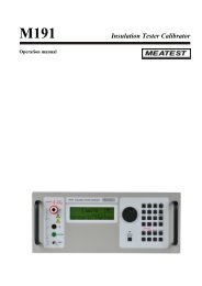
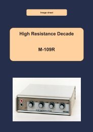
Front panel<br />
The front panel of the calibrator includes a flat luminiscent display, control buttons and output terminals. The<br />
following picture shows the control part of the front panel.<br />
3 5<br />
1 2 4 6 7<br />
1 Display buttons<br />
There are five buttons below the display, whose meaning changes depending on the contents of the display.<br />
These buttons usually call-up the MENU, allow range change, step, logging of values etc.<br />
2 Cursor buttons<br />
Using these buttons, the cursor can be controlled within allowed limits on the display. The keyboard includes<br />
two buttons () which allow the cursor to be set to the required position at the display. The cursor can be<br />
moved to the left or right. These buttons are usually used to step through the options and to move from one<br />
option to another or between the menu levels. Numeric values can be set in some control modes as well. In these<br />
cases, the buttons marked (∧, ∨) allow the user to increase or decrease the number at the cursor button.<br />
The central button is used to confirm the selection (ENTER), or to SELECT from the menu.<br />
3 Potentiometer<br />
The potentiometer integrates several functions. By turning the knob to the left or right, the user can:<br />
• step through the options<br />
• enter numeric values<br />
Operation manual v42 7
M-140 <strong>Multifunction</strong> <strong>Calibrator</strong> MEATEST<br />
The function of the potentiometer can usually be performed by the cursor buttons. The central button is used to<br />
confirm the selection (ENTER).<br />
4 Numeric keyboard<br />
The keyboard allows the entry of numeric values on the display. The central button is used to confirm the<br />
selection (ENTER). CANCEL button can be used to cancel the entry.<br />
5 Function buttons<br />
Function buttons can be used to call-up the functions of the calibrator directly. The following buttons are<br />
provided:<br />
function<br />
DC voltage<br />
AC voltage<br />
DC current<br />
AC current<br />
resistance / capacitance<br />
power / energy<br />
frequency<br />
internal multimeter<br />
simulation of temperature sensors<br />
button<br />
U / DC<br />
U / AC<br />
I / DC<br />
I / AC<br />
R – C<br />
P – E<br />
F<br />
METER<br />
T<br />
After the function mode is changed, the parameters of the respective function are restored. If the respective<br />
function was never used, the calibrator resets to its reference values. Reference values for individual functions<br />
are listed below.<br />
function value parameters<br />
DC voltage 10V - -<br />
AC voltage 10 V f = 1000 Hz<br />
DC current 100 mA - -<br />
AC current 100 mA f = 1000 Hz<br />
resistance<br />
100 kΩ<br />
capacitance 1 µF<br />
power 100 W f = 100 Hz *1<br />
energy<br />
frequency 1000 Hz U = 1 Vsym<br />
multimeter 10 V DC voltage<br />
simulation of temperature sensors 100 o C Pt 100/1.385, ITS90<br />
cold junction temperature of TC sensors 23 o C R<br />
*1<br />
U = 100 V, I = 1 A, PF(power factor) = 1 LA, active power is displayed in Watts<br />
8 Operation manual v42
MEATEST<br />
M-140 <strong>Multifunction</strong> <strong>Calibrator</strong><br />
6 Output / input terminals buttons<br />
OUTPUT button is used to connect the output signal of the calibrator to the output terminals. The connection is<br />
confirmed by red LED and a symbol at the display.<br />
METER button can be used to connect the input terminals to the internal multimeter. The connection is<br />
confirmed by green LED.<br />
7 Output / input terminals<br />
Output signal of the calibrator is connected to the output terminals. Current ranges are connected to +I / -I<br />
terminals, frequency output is connected to FREQ terminal. All other functions (voltage, resistance,<br />
capacitance) are connected to Hi / Lo terminals.<br />
GND terminal is connected to the chassis of the calibrator. It is connected to the ground terminal of the mains<br />
plug. Using the SETUP MENU of the calibrator, the output terminals of the calibrator can be grounded as well.<br />
Grounding is done internally by connecting Lo and GND terminals using a relay. This circuit design is suitable<br />
for most calibrations, when the object (multimeter) being calibrated is floating.<br />
AUXILIARY connector creates input of internal multimeter. It includes a limited range of output signals of the<br />
calibrator as well. The layout of individual pins and their meanings are listed in the following table.<br />
Auxiliary connector can be used with one of cable adapters Opt. 40, 60, 70, Opt. 140-41. <strong>Calibrator</strong> can<br />
recognize which type of adapter is connected and displays the information on front panel display.<br />
Operation manual v42 9
M-140 <strong>Multifunction</strong> <strong>Calibrator</strong> MEATEST<br />
pin label signal Limitation<br />
1 0V5MER common terminal of multimetr power supply source<br />
2 GND ground (protection earth)<br />
3 SIMLI RC simulator output, current terminal Li Umax.= 10Vpp, Imax.=40mA<br />
4 SIMLU RC simulator output, voltage terminal Lu Umax.= 10Vpp, Imax.=40mA<br />
5 GND ground (protection earth)<br />
6 L common terminal of multimeter input<br />
7 -U low output terminal for DC voltage range<br />
8 -I low output terminal for DC current range<br />
9 NG2 sort function output, contact 2 of sort relay Umax.=50Vpp, Imax.=100 mA<br />
10 PTLI resistance temperature sensor input terminal Li Umax.= 10Vpp. R
MEATEST<br />
M-140 <strong>Multifunction</strong> <strong>Calibrator</strong><br />
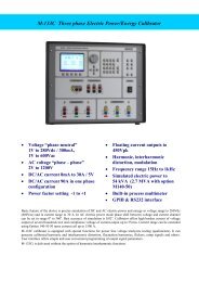
8 Display<br />
1a 1b 1c 1d 1e 2a 3 2b 1g 1f<br />
The display is divided to three horizontal sections:<br />
1. OUTPUT section<br />
This section displays the set-up values of generated signals and the data related to the calibrator status. The<br />
section includes the following types of data:<br />
a) Information line<br />
• designation of display section: OUTPUT<br />
• error messages. The messages appear when an attempt is made to set up an invalid state of the<br />
calibrator, if analogue circuits of the calibrator are overloaded or if a communication error occurs<br />
when the calibrator is controlled using GPIB bus.<br />
• real date and time, if its display is set-up in the setup menu.<br />
b) Auxiliary data<br />
This line displays the total value of output signal if a non-zero relative deviation is set.<br />
c) Main data<br />
This line displays the main data of the output signal and the unit of measurement (using double size<br />
signs). The line also includes two symbols (▼▲) to define the actual position of the cursor during<br />
adjustment of the value. buttons can be used to move the cursor and ∧, ∨ buttons to change the<br />
value. (The value can be also changed using the potentiometer).<br />
d) Monitoring line<br />
This line displays the numbers entered using the numeric keyboard when the main data are set using the<br />
numeric keyboard. The information allows the entered information to be checked.<br />
e) Minor data<br />
There are two lines displaying the minor data of the output signal, especially:<br />
• set relative deviation from main set value in %<br />
• frequency (for DC voltage, current, power, energy functions)<br />
• set value of current, voltage or power factor (phase) for power, energy functions<br />
• value of R0 resistance and the type of resistance temperature sensor<br />
Operation manual v42 11
M-140 <strong>Multifunction</strong> <strong>Calibrator</strong> MEATEST<br />
• cold junction temperature of TC sensors and the selected type of TC sensor<br />
• value of amplitude and shape type for frequency function<br />
f) Information section<br />
The information section located in the right part of the display displays additional information related to<br />
the selected function:<br />
• symbol of connected or disconnected output terminals.<br />
At the same time, a LED located above the OUTPUT button is lit.<br />
• information about remote/local control of the calibrator. If the calibrator is controlled remotely,<br />
REM is displayed. If the calibrator is controlled locally using the keyboard, LOCAL is displayed.<br />
• information about the use of 50-turn coil (COIL x50) at the current output of the calibrator, if this<br />
feature is turned on using the SETUP menu.<br />
• information about the type of connected cable adapter, if used<br />
• information about the grounding method of output terminals: GND I, GND U as set up using the<br />
setup menu.<br />
g) Information about the uncertainty of the output signal<br />
This section displays the maximum error of the main value of the output signal. The value is calculated<br />
using the main specification listed in the User’s Manual and it is displayed in %.<br />
2. INPUT section<br />
This section displays the values measured by the multimeter. The section includes following data:<br />
a) Main value of measured signal<br />
This line displays the measured value and the unit of measurement. If the input signals exceed the<br />
permitted range, OVERFLOW is displayed.<br />
b) Designation of selected function of the multimeter<br />
Symbolic display of selected function of the multimeter: V DC, mA DC, mV DC, R 4W, Freq, T TC, T<br />
RTD, SGS, ACAL.<br />
3. Display buttons section<br />
This line displays the symbolic descriptions which define the meaning of four related display buttons. The<br />
respective meanings are as follows:<br />
symbol button function note<br />
x 10<br />
increase set value 10 x<br />
: 10 decrease set value 10 x<br />
Shape selection of signal shape only for U, I, F functions<br />
+/- reversed polarity of output voltage and current only for DC U, DC I functions<br />
EXIT move up one level only for F, P-E functions<br />
Calib.<br />
SETUP<br />
enter the calibration menu<br />
enter the setup menu<br />
TC type selection of thermocouple sensor type only for T function<br />
RTD type selection of resistance temperature sensor type only for T function<br />
f enter the frequency of the signal only for U, I function<br />
MODE select the unit of measurement only for AC P-E function<br />
12 Operation manual v42
MEATEST<br />
M-140 <strong>Multifunction</strong> <strong>Calibrator</strong><br />
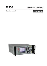
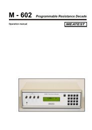
Rear panel<br />
The rear panel of the calibrator includes ventilation holes, power cord socket with fuse, mains voltage selector,<br />
mains switch, IEEE 488 connectors for connection to GPIB bus and type plate with serial number.<br />
5<br />
1<br />
2<br />
4 3<br />
1 air inlet - forced ventilation<br />
2 air outlet - forced ventilation<br />
3 GPIB, RS-232 connectors<br />
4 power cord socket with fuse, mains voltage selector, mains switch<br />
5 type plate<br />
Operation manual v42<br />
13
M-140 <strong>Multifunction</strong> <strong>Calibrator</strong> MEATEST<br />
Control of the calibrator<br />
Selection of function<br />
After the power is switched on and the initial checks complete, the calibrator resets to its reference status, i.e. DC<br />
voltage output with set value of 10 V and output terminals disconnected. Internal multimeter is switched off. The<br />
status of the calibrator can be changed using the buttons located at the front panel in one of the following ways:<br />
1. Change of function by pressing one of direct function buttons<br />
After pressing one of the U, I, DC-AC, R-C, P-E, F, T, METER buttons, the calibrator switches to the desired<br />
function mode and resets to the reference or to the most recently used parameter setting.<br />
2. Connection /disconnection of output terminals<br />
After pressing the OUTPUT button, the output terminals of the calibrator are connected/disconnected.<br />
3. Connection /disconnection of multimeter<br />
After pressing the INPUT button, the multimeter starts measuring the value present at the input terminals,<br />
depending on the function mode of the multimeter. The measurement is only possible when any of Opt. 140-xx<br />
adapters is connected to the AUXILIARY connector.<br />
4. Entry to the setup menu<br />
After pressing the SETUP button, options of the SETUP MENU appear on the display and the display buttons<br />
allow the entry to the calibration mode (CALIB) or entry to the mode when the calibrator is used as a tester<br />
(TESTER). Previous function is restored by pressing of EXIT display button.<br />
Setting the value of output signal<br />
All function modes allow several methods of setting the main value of the output signal:<br />
Entry of the value using numeric keyboard<br />
• use the numeric keyboard to select the desired value. After the first digit is entered, symbols of unit<br />
of measurements are displayed above the display buttons. The monitor line displays the symbols<br />
[ _ _ _ _ _ _ _ _ ].<br />
• the same entry can be started by pressing the central cursor button<br />
• after the entry is complete (the value is displayed on the monitor line), press the display button<br />
below the desired unit of measurement (V, mV or µV in the example below)<br />
• the value is copied to the main display and the monitor line disappears.<br />
14 Operation manual v42
MEATEST<br />
M-140 <strong>Multifunction</strong> <strong>Calibrator</strong><br />
Entry of the value using cursor buttons<br />
• press , ∧ or ∨ button. The display now includes cursor marks which point to the active digit.<br />
• ∧ and ∨ buttons can be used to change the active digit. buttons can be used to change the<br />
position of the cursor marks<br />
• to get to the default screen, press EXIT button or keep pressing the center cursor button until there<br />
is no [ _ _ _ _ _ _ _ ] under any value. All values can be set using the buttons or the potentiometer.<br />
Entry of the value using the potentiometer<br />
• press the potentiometer knob. The display now includes cursor marks which point to the active<br />
digit<br />
• turn the knob to change the active digit<br />
• press the potentiometer knob to change to the mode which allows to change the value of the active<br />
digit. ← and → symbols are displayed above the active digit. Active digit can be changed by<br />
turning the knob.<br />
• turn the knob to change back to the mode which allows to change the position of the active digit.<br />
• to get to the default screen, keep pressing the center cursor button until there is no [ _ _ _ _ _ _ _ ]<br />
under any value, or press EXIT button. All values can be set using the buttons or the potentiometer.<br />
Reverse polarity<br />
In DC voltage and DC current modes, the polarity of the output value can be reversed by pressing +/- display<br />
button. „ - “ symbol appears in front of the main data value.<br />
Operation manual v42 15
M-140 <strong>Multifunction</strong> <strong>Calibrator</strong><br />
MEATEST<br />
Setting relative deviation<br />
All function modes of the calibrator except frequency mode allow a relative deviation of output value from the<br />
main data to be set using a separate display. Relative deviation is displayed in the “minor data” section of the<br />
display and is designated with „ ∆%= 00.0000 % “ symbol. The relative deviation can be entered using one of<br />
the methods described above, e.g. using the numeric keyboard, cursor keys or the potentiometer.<br />
Setting relative deviation using numeric keyboard<br />
• keep pressing the center cursor button until [<br />
_ _ _ _ _ _ _ ] symbols appear under the relative<br />
deviation value in the “minor data” section of the display<br />
• enter the desired deviation and confirm the value by pressing “ % “ display button or by pressing<br />
ENTER on the numeric keyboard<br />
• the auxiliary line below the main data on the display displays the total value of output signal<br />
including the unit of measurement<br />
• the value of the signal at output terminals is: the value indicated by the main display + ∆ %.<br />
Maximum relative deviation which can be entered is ± 30.000 %.<br />
The deviation can be positive or negative. If negative deviation is desired, press the display button labeled +/-. If<br />
positive deviation is then desired, press “ +/- “ button again. The polarity of the relative deviation can be<br />
reversed using the cursor buttons or the potentiometer as well.<br />
Setting relative deviation using cursor keys<br />
• keep pressing the center cursor button until [<br />
_ _ _ _ _ _ _ ] symbols appear under the relative<br />
deviation value<br />
• press , ∧ or ∨ button. The display now includes cursor marks which point to the active digit<br />
• ∧ and ∨ buttons can be used to change the active digit. buttons can be used to change the<br />
position of the cursor marks<br />
• to get to the default screen, keep pressing the center cursor button until there is no [ _ _ _ _ _ _ _ ]<br />
under any value, or press EXIT button. All values can be set using the buttons or the<br />
potentiometer..<br />
16<br />
Operation manual v42
MEATEST<br />
M-140 <strong>Multifunction</strong> <strong>Calibrator</strong><br />
Setting relative deviation using potentiometer<br />
• keep pressing the center cursor button until [ _ _ _ _ _ _ _ ] symbols appear under the relative<br />
deviation value in the “minor data” section of the display<br />
• press the potentiometer knob. The display now includes cursor marks which point to the active<br />
digit. Turn the knob to change the value of the active digit<br />
• press the potentiometer knob to change to the mode which allows to change the position of the<br />
active digit. ← and → symbols are displayed above the active digit. The position of the active digit<br />
can be changed by turning the knob.<br />
• turn the knob to change back to the mode which allows to change the value of the active digit<br />
• to get to the default screen, keep pressing the center cursor button until there is no [ _ _ _ _ _ _ _ ]<br />
under any value, or press EXIT button. All values can be set using the buttons or the potentiometer.<br />
If a non-zero relative deviation is set, the main data can be changed as well. The value of the output signal is<br />
always recalculated. If a zero relative deviation is set, the “minor data” section is not displayed.<br />
Change of value by factor of ten<br />
All functions of the calibrator allow the increase of the output value by 10 or reduction of the output value by 10.<br />
Such operation is equivalent to the change of internal range only in U, I, P-E modes. If the change results in<br />
overflow or underflow of calibrator’s range, an error message appears:<br />
Value too large !<br />
Value too small !<br />
if the resulting value is too large<br />
if the resulting value is too small<br />
Range change<br />
• Press the display button labeled “ x10 “ if you want to increase the range, “ :10 “ to decrease the<br />
range.<br />
• The main value shown on the display is increased 10x (reduced 10x)<br />
P-E function changes the current, not voltage, when the range is changed.<br />
R-C function changes the set value 10x. The procedure, however, cannot be used to step the internal<br />
resistance/capacitance ranges, which are not decimal.<br />
T function also has other than decimal ranges and the change of set value 10x therefore does not correspond to<br />
internal range change. Internal range change in this case depends on the temperature sensitivity of the<br />
resistance/capacitance.<br />
Connection / disconnection of output terminals<br />
After switching on the output terminals are disconnected in all modes. Press the OUTPUT button to connect the<br />
output signal to the terminals. Red LED above the OUTPUT button is lit and the information field on the<br />
display shows the following symbol .<br />
Press the OUTPUT button again to disconnect the output terminals. Red LED goes off and the information field<br />
on the display shows the following symbol .<br />
During mode change, output terminals are always disconnected. Output terminals are disconnected also when<br />
changing between voltage and current ranges or when changing between AC and DC ranges is performed.<br />
Operation manual v42 17
M-140 <strong>Multifunction</strong> <strong>Calibrator</strong><br />
MEATEST<br />
If voltage over 100 V is set in the voltage mode, special algorithm must be followed to connect the output<br />
terminals. The algorithm is described in the „Generation of calibrated voltage“ chapter of this Manual.<br />
Setting the frequency<br />
Frequency can only be selected in AC voltage (ACU) mode, AC current (ACI) mode , power (P-E) mode and<br />
frequency (f) mode. In each mode the frequency has a slightly different meaning and the frequency is therefore<br />
set in a different manner.<br />
AC voltage (ACU), AC current (ACI)<br />
Set value of frequency is included in the “minor data” section of the display in ACU, ACI, P-E modes.<br />
Frequency change<br />
• First select the AC voltage or AC current mode by pressing U (I), AC buttons or selecting the P-E<br />
mode using the display. Frequency value „f = xxx.xx Hz“ appears in the “minor data” section of<br />
the display. “ f “ symbol is displayed above one of the display buttons.<br />
• After “ f “ display button is pressed, [ _ _ _ _ _ _ _ ] symbols appear below the frequency value.<br />
Numeric keyboard can be used to enter the desired value. Press “ Hz “ or “ kHz “ to confirm the<br />
value. The value can be set using the buttons or the potentiometer.<br />
If too large or too small value is entered, the calibrator displays the maximum (minimum) value which is allowed<br />
for the selected function.<br />
Frequency (F)<br />
Set value of frequency is the main data on the display and the main parameter of the signal. Main data can be set<br />
by direct entry using the numeric keyboard, potentiometer or by changing the digit at the current cursor position.<br />
The setting procedure is described in the “Setting the value of output signal”.<br />
18<br />
Operation manual v42
MEATEST<br />
M-140 <strong>Multifunction</strong> <strong>Calibrator</strong><br />
If frequency larger or smaller than the calibrator’s range is entered, the calibrator displays an error message:<br />
„Value is too large (small)“.<br />
Generation of calibrated voltage<br />
The multifunction calibrator provides calibrated DC and AC voltage. Output terminals for voltage ranges are<br />
labeled “ Hi “ and “ Lo “ at the front panel. Depending on the setting of the calibrator, voltage up to 1000 Vef<br />
can be present at the terminals .<br />
DC voltage range is 0 to 1000 V.<br />
AC voltage range is 100 µV V to 1000 V.<br />
Output voltage up to 20 V is available at AUXILIARY connector. It can be used only with cable adapter Opt.<br />
140-41.<br />
Control in the voltage mode<br />
• Press “U” button on the calibrator and then select AC or DC mode by pressing “DC-AC” button. The<br />
display shows the following data:<br />
* main data of set voltage<br />
* relative deviation<br />
* uncertainty of output voltage<br />
* frequency (when AC voltage is generated)<br />
* total value of output voltage when non-zero relative deviation is set<br />
• Set the desired value of voltage, including polarity when necessary, frequency and relative deviation. The<br />
signal is yet not connected to the output terminals. The information section of the display shows the symbol<br />
which informs about the disconnection of output terminals.<br />
• Press OUTPUT button.<br />
• Red LED is lit above the OUTPUT terminals to signal the connection of the signal to the output terminals;<br />
the information ion section of the display shows the symbol .<br />
• Calibrated voltage corresponding to set parameters is present at the output terminals.<br />
Operation manual v42<br />
19
M-140 <strong>Multifunction</strong> <strong>Calibrator</strong> MEATEST<br />
Control sequence when output voltage over 100 V is selected<br />
When output voltage over 100 V is selected, the information section of the display shows the symbol which<br />
informs that a life-threatening voltage will be present at the output terminals. If the output terminals are currently<br />
connected, they will be disconnected when output voltage over 100 V is selected. OUTPUT button must be<br />
pressed to reconnect the output signal to the output terminals. After the OUTPUT button is pressed, an<br />
interrupted beep is sound, OUTPUT LED is lit and the information section of the display shows the symbol<br />
notifying the user about the connection of the dangerous output signal to the output terminals.<br />
Voltage, polarity, frequency, absolute and relative deviation can be set without the outputs being disconnected.<br />
The output terminals are automatically disconnected when changing between AC and DC ranges or when<br />
changing the function mode.<br />
Using AUTOCAL function<br />
To remove the effect of short-term drift and temperature dependency of small DC voltages, AUTOCAL function<br />
can be used. It can only be activated in the calibration mode. “Calibration mode” lists the respective procedure.<br />
Overloading of terminals<br />
If the output terminals are overloaded or short-circuited in the voltage mode, the calibrator disconnects the signal<br />
from the output terminals and reports „Overload U output“ error.<br />
ATTENTION DANGEROUS VOLTAGE<br />
Never touch the measurement circuit when voltage over 50 V is set and<br />
output terminals are connected!<br />
When working with voltages over 50 V, rules for work with dangerous<br />
voltage must be adhered to.<br />
ATTENTION DANGEROUS VOLTAGE<br />
When the calibrator is controlled remotely, it is not possible to disconnect<br />
the output voltage using the buttons located at the front panel!<br />
The calibrator must be first switched to local control mode by pressing the<br />
LOCAL button and then the output terminals can be disconnected or the<br />
mains switch must be switched off !<br />
20 Operation manual v42
MEATEST<br />
M-140 <strong>Multifunction</strong> <strong>Calibrator</strong><br />
Generation of calibrated current<br />
The multifunction calibrator provides calibrated DC and AC current. Output terminals for voltage ranges are<br />
labeled “ +I “ and “ -I “ at the front panel. The terminals can carry high current and are the only terminals to<br />
which the calibrated object can be connected. Depending on the setting of the calibrator, current up to 20 A ef can<br />
be driven by the terminals.<br />
DC current range is 0 to 20 A<br />
AC current range is 1µA to 20 A<br />
When 50-turn coil (option 140-50) is used, AC current range is 50µA to 1000 A. Output current up to 20 mA is<br />
available at AUXILIARY connector and it is accessible via cable adapter Opt. 41-41 only.<br />
Control in the current mode<br />
• Press “I” button on the calibrator and then select AC or DC mode by pressing “DC-AC” button. The display<br />
shows the following data:<br />
* main data of set current<br />
* relative deviation<br />
* uncertainty of output current<br />
* frequency (when AC current is generated)<br />
* total value of output current when non-zero absolute or relative deviation is set<br />
* time after which the output terminals will be disconnected when the output current over 10 A is<br />
selected.<br />
• Set the desired value of voltage, including polarity when necessary, frequency and relative deviation. The<br />
signal is yet not connected to the output terminals. The information section of the display shows the<br />
symbol which informs about the disconnection of output terminals.<br />
• Connect the load or short the output terminals labeled +I, -I.<br />
• Press OUTPUT button.<br />
• Red LED is lit above the OUTPUT terminals to signal the connection of the signal to the output terminals;<br />
the information section of the display shows the symbol .<br />
• Calibrated current corresponding to set parameters is driven by the output terminals.<br />
• If COILx50 function is activated (see below - Setup functions menu), the optional 50-turn coil must be<br />
connected to output terminals. The calibrator can be used to calibrate 50 µA to 1000 A ammeters. The<br />
calibrator generates AC and DC current within the range up to 20 A.<br />
CAUTION<br />
If GND terminal is connected to Lo, -I terminals, it is prohibited to connect<br />
external load to GND / Hi or GND / +I terminals. Such connection can<br />
damage the calibrator.<br />
Operation manual v42 21
M-140 <strong>Multifunction</strong> <strong>Calibrator</strong> MEATEST<br />
Overloading the terminals<br />
When external circuit connected to current output terminals is disconnected or there is higher voltage at the load<br />
than permitted, the calibrator disconnects the output terminals and displays „Overload I output“ message. The<br />
same message can be displayed when 50-turn coil is used for AC current output at frequencies above 80 Hz. It<br />
depends on the set current and the type of ammeter connected.<br />
If the output terminals are disconnected due to time limitation of output current over 10 A, the calibrator displays<br />
„Current timeout !“ message.<br />
Generation of non-harmonic shapes<br />
The multifunction calibrator can generate non-harmonic periodic signals with predefined shape. To allow the<br />
setting of a non-harmonic output shape, the calibrator must be switched to AC U or AC I mode. In both cases, an<br />
indication of the type of output shape (Shape xxxxx) is displayed under the frequency value. Press the respective<br />
display button to change the shape of the output signal.<br />
The calibrator can generate the following shapes:<br />
• SINE harmonic<br />
• PWM POS squarewave - positive, with adjustable duty cycle<br />
• PWM SYM squarewave - symmetrical, with adjustable duty cycle<br />
• PWM NEG squarewave - negative, with adjustable duty cycle<br />
• RAMP A ramp, symmetrical positive<br />
• RAMP B ramp, symmetrical negative<br />
• TRIANGLE triangular, symmetrical<br />
• LIM SINE harmonic with amplitude limitation (truncated sin)<br />
Generation of non-harmonic signals has some limitations:<br />
• non-harmonic voltages can be generated in the 0.1 Hz to 1000 Hz frequency range<br />
• non-harmonic currents can be generated in the 0.1 Hz to 120 Hz frequency range<br />
• generation of these signals is limited to the voltage range up to 200 V and current range up to 2 A<br />
• non-harmonic signals cannot be generated in the P-E (power-energy) mode.<br />
Control in the non-harmonic mode<br />
• Select AC voltage or AC current mode. The main section of the display shows the following data:<br />
* main data of set current or voltage, unit of measurement<br />
* relative deviation<br />
* frequency<br />
* selected SHAPE of the output signal<br />
• Keep pressing SHAPE display button to select the desired shape of the output signal:<br />
The output terminals are automatically disconnected when changing the shape of the output signal or when<br />
changing the relative deviation ∆%, if a non-zero relative deviation is set.<br />
Displayed information<br />
When non-harmonic output shape is selected, the display shows additional information:<br />
• besides the main amplitude data, „pk“ index is displayed, notifying that the displayed main value is the peak<br />
value. Symbol which displays the shape of the output signal is displayed too.<br />
22 Operation manual v42
MEATEST<br />
M-140 <strong>Multifunction</strong> <strong>Calibrator</strong><br />
• below the main data, an information about the shape type „Shape xxxxx“ is displayed.<br />
• below the main data, calculated effective value of the output signal is displayed.<br />
• for squarewave signals, set value of duty cycle „PWM= xx %“ is displayed.<br />
Simulation of resistance and capacitance<br />
The multifunction calibrator can simulate an exact value of resistance or capacitance. The outputs of the<br />
simulator are connected to Hi – Lo terminals and to AUXILIARY connector (pins 20, 21, 22, 23). 4W resistance<br />
is accessible only via cable adapter Opt. 70.<br />
Only two-wire wire connection is available on the front panel terminals Hi-Lo. Both two-wire and four-wire<br />
connection is possible only through AUXILIARY connector. The terminals SIMHI - SIMLI are current<br />
terminals and SIMHU - SIMLU are voltage sensing terminals. Cable adapter Option 70 or cable adapter Option<br />
140-41 must be used for four-wire connection. Type of cable adapter currently connected to the AUXILIARY<br />
connector, is displayed on the display. If Option 70 is connected, label CA 140-70 is displayed in the right side.<br />
If Option 140-4141 is connected, label CA 140-41 is displayed.<br />
Cable adapter Option 70 can be used for four-wire connecting of simulated resistance only. In compare with<br />
direct two-wire wire connection through output terminals Hi – Lo, accuracy of resistance is better with Option 70, see<br />
Technical data. If Cable adapter Option 70 is connected to the AUXILIARY connector, only resistance mode<br />
and resistance temperature simulation mode can be chosen.<br />
The resolution of resistance and capacitance depends on the set value and corresponds to 0.01 % of set value.<br />
Minimum set value is 0.01 Ω<br />
Resistance simulation range is 0 Ω to 50 MΩ.<br />
Capacitance simulation range is 0.9 nF to 50 µF.<br />
Control in the resistance and capacitance mode<br />
• press R-C button on the calibrator. The display shows the set resistance.<br />
• If you want to simulate a capacitance, press R-C button again. The display shows the set capacitance.<br />
• The display shows the following data:<br />
* main data of set resistance (capacitance)<br />
* relative deviation of resistance (capacitance)<br />
* uncertainty of set resistance (capacitance)<br />
* total value of resistance (capacitance) if non-zero deviation is set<br />
Operation manual v42<br />
23
M-140 <strong>Multifunction</strong> <strong>Calibrator</strong><br />
MEATEST<br />
• Set desired value of resistance (capacitance) or relative deviation. The value can be set using numeric<br />
keyboard, potentiometer or cursor buttons. Simulated resistance (capacitance) is not yet connected to the<br />
output terminals. The information section of the display shows the symbol which informs about the<br />
disconnection of output terminals.<br />
• Connect the object to be calibrated to the output terminals labeled Hi - Lo.<br />
• Press OUTPUT button.<br />
• Red LED is lit above the OUTPUT terminals to indicate the connection of simulated resistance<br />
(capacitance) to the output terminals. The information section of the display shows the symbol<br />
Simulated resistance (capacitance) is connected to output terminals.<br />
Setting relative deviation<br />
• Keep pressing the center cursor button until [ _ _ _ _ _ _ _ ] symbols appear under the relative deviation<br />
value (∆% = xx.xxxx %).<br />
• The value can be set using numeric keyboard, potentiometer or cursor buttons. Confirm the value by<br />
pressing “%” display button or by pressing ENTER.<br />
Limitations resulting from electronic simulation<br />
Electronic simulation of resistance and capacitance allows setting of a wide range of values with accuracy<br />
sufficient for calibration of common multimeters. Electronic simulation has the following limitations:<br />
• measurement current supplied by the multimeter to be calibrated must not exceed the value specified by the<br />
calibrator’s documentation. If the current is exceeded, the accuracy of simulated value is not guaranteed.<br />
• maximum peak voltage at Hi - Lo terminals supplied by the multimeter to be calibrated must not exceed<br />
specified limits. If the test voltage is exceeded, calibrator disconnects output terminals. Overload message is<br />
displayed on the display.<br />
24<br />
Operation manual v42
MEATEST<br />
M-140 <strong>Multifunction</strong> <strong>Calibrator</strong><br />
Frequency dependence of resistance and capacitance<br />
Electronic simulator of resistance can be used with DC and AC test signal. Electronic simulator of capacitance<br />
can be used in AC range from 20 Hz to 1000 Hz.<br />
Operation manual v42 25
M-140 <strong>Multifunction</strong> <strong>Calibrator</strong><br />
MEATEST<br />
Generation of electric power and energy<br />
The multifunction calibrator can generate exact value of electric power and energy. P-E function provides output<br />
voltage at Hi - Lo terminals and output current at +I - -I terminals. Lo and -I terminals are electrically connected.<br />
Power setting range:<br />
Voltage setting range:<br />
Current setting range:<br />
Power factor setting range:<br />
Frequency setting range:<br />
0.0 VA to 2400 VA<br />
0.2 V to 240 V<br />
0.01 A to 10 A<br />
-1 to +1 (phase –90 to +90 °)<br />
DC, 40 Hz to 400 Hz<br />
Control in power generation mode<br />
• Press “P-E” button on the calibrator and then select AC or DC mode by pressing “DC-AC” button. The<br />
display shows set power value.<br />
• The display shows the following data::<br />
* main value of set power in selected unit of measurement VA, W, VAr<br />
* power factor value PF in negative polarity LA or positive polarity LE or the phase shift between the<br />
voltage and current in °.<br />
* frequency, if AC power is selected<br />
* voltage at Hi - Lo terminals<br />
* current through +I - -I terminals<br />
* uncertainty of set power<br />
• Set desired value of power using numeric keyboard, potentiometer or cursor buttons. Output power is not<br />
yet connected to the output terminals. The information section of the display shows the symbol which<br />
informs about the disconnection of output terminals..<br />
• Connect the instrument to be calibrated to Hi - Lo and +I - -I terminals or short the +I - -I terminals.<br />
• Press OUTPUT button.<br />
• Red LED is lit above the OUTPUT terminals to indicate the connection of simulated electrical power to the<br />
output terminals; the information section of the display shows the symbol<br />
Desired power is connected to output terminals.<br />
Display modes<br />
26<br />
Operation manual v42
MEATEST<br />
M-140 <strong>Multifunction</strong> <strong>Calibrator</strong><br />
The calibrator can display AC power in one of three ways:<br />
• apparent power in VA<br />
• active power in W<br />
• reactive power in VAr<br />
Keep pressing MODE display button to change the function mode. Along with mode change, the power display<br />
(depending on set power factor) and unit of measurement change as well. If DC power is generated, it is always<br />
displayed in Watts.<br />
The calibrator can display the phase relation of output voltage and current as power factor (–1 to +1) or as phase<br />
shift in degrees (0 to 360 °). SETUP setup menu is used to change the method of displaying the phase relation.<br />
Power setting modes<br />
The calibrator allows several ways of setting the value of generated power.<br />
1. Setting the main power value<br />
• The main value can be changed using numeric keyboard, changing the digit at the cursor position<br />
after selecting the cursor position with buttons, by range change using „x10“, „:10“ display<br />
buttons, or using the potentiometer.<br />
• Output power is changed by changing the value of output current.<br />
Operation manual v42 27
M-140 <strong>Multifunction</strong> <strong>Calibrator</strong> MEATEST<br />
2. Setting the voltage<br />
• The main power value can be changed by changing the voltage.<br />
• Select P-E mode and then keep pressing the center cursor button until [ _ _ _ _ _ _ _ ] symbols<br />
appear under the voltage (U = xxx.xxxx V).<br />
• The value can be set using numeric keyboard and confirmed by pressing µV, mV, V display button.<br />
The value can be set using cursor buttons or potentiometer as well.<br />
• Main power value is recalculated using new set voltage and existing setting of current and power<br />
factor.<br />
3. Setting the current<br />
• The main power value can be changed by changing the current..<br />
• Select P-E mode and then keep pressing the center cursor button until [ _ _ _ _ _ _ _ ] symbols<br />
appear under the current (I = xx.xxxx A).<br />
• The value can be set using numeric keyboard and confirmed by pressing µA, mA, A display button.<br />
The value can be set using cursor buttons or potentiometer as well..<br />
• Main power value is recalculated using new set current and existing setting of voltage and power<br />
factor.<br />
28 Operation manual v42
MEATEST<br />
M-140 <strong>Multifunction</strong> <strong>Calibrator</strong><br />
4. Setting the power factor (AC power only)<br />
• If W or Var is indicated, the main power value can be changed by changing the power factor.<br />
Change of power factor does not change the output apparent power.<br />
• Select P-E mode and then keep pressing the center cursor button until [ _ _ _ _ _ _ _ ] symbols<br />
appear under the power factor symbols (PF = x.xxx LA (LE) or Phase = xxx.x).<br />
• The value can be set using numeric keyboard and confirmed by pressing LA/LE (°) button or by<br />
pressing ENTER.<br />
• Main power value is recalculated using new set power factor and existing setting of current and<br />
voltage. The calculation is only made if active or reactive power is displayed.<br />
In the power generation mode, relative deviation cannot be set.<br />
If the power factor is set to define the phase relation of voltage and current, confirmation of entered<br />
value by pressing LA button means positive phase, LE means negative phase.<br />
Setting the energy<br />
Keep pressing the P-E button to switch to the energy generation mode. Auxiliary data display area<br />
shows the time in seconds and the energy delivered to output terminals after pressing the OUTPUT<br />
button given the existing setting of voltage, current, frequency and power factor. Time setting range is<br />
1.1 s to 1999 s.<br />
Operation manual v42 29
M-140 <strong>Multifunction</strong> <strong>Calibrator</strong> MEATEST<br />
The energy value can be set in two ways:<br />
Direct setting of energy<br />
• Select the energy mode and then keep pressing the center cursor button until [ _ _ _ _ _ _ _ ] symbols<br />
appear under the time value (E = xxx.xxxx) supplemented with indication of the set mode.<br />
• The value can be set using numeric keyboard, cursor buttons or potentiometer and confirmed by pressing<br />
Ws/kWs/MWs, VAs/kVAS/MVAs or VArs/kVArs/MVArs display buttons depending on the set mode. The<br />
value can also be confirmed by pressing ENTER.<br />
• Time value is recalculated using new set energy.<br />
Setting the time<br />
• Select the energy mode and then keep pressing the center cursor button until [ _ _ _ _ _ _ _ ] symbols<br />
appear under the time value (t = xxx.x s).<br />
• The value can be set using numeric keyboard, cursor buttons or potentiometer and confirmed by pressing<br />
“s” display button depending on the set mode. The value can also be confirmed by pressing ENTER.<br />
• Energy value is recalculated using new set time.<br />
Grounding of the calibrator and the instrument to be calibrated in the P-E mode<br />
When calibrating the power and energy meters with separate voltage and current circuits, it is advisable<br />
to select GND U ON and GND I ON (both grounding methods on) on the M-140 calibrator. This<br />
setting will ground both the current and voltage output of the calibrator.<br />
If the instrument to be calibrated has electrically connected and not grounded current and voltage<br />
inputs, GND U ON and GND I OFF should be selected on the M-140 calibrator.<br />
If Lo and -I terminals on the calibrator are connected AND the same terminals are connected at the<br />
instrument to be calibrated, resulting voltage drop at the current cables can damage the relay which<br />
interconnects Lo and -I terminals with GND terminal in the calibrator.<br />
“Operating examples“ chapter provides more information concerning correct connection of powermeters and<br />
energy meters to the calibrator.<br />
30 Operation manual v42
MEATEST<br />
M-140 <strong>Multifunction</strong> <strong>Calibrator</strong><br />
Uncertainty calculation of set power<br />
Uncertainty of set power displayed on the Accuracy line of the display is calculated according to the following<br />
formula:<br />
for active power d P = √ ( dU 2 + dI 2 + dPF 2 + 0.03 2 ) [%]<br />
for reactive power d P = √ ( dU 2 + dI 2 + dPF* 2 + 0.03 2 ) [%]<br />
for apparent power d P = √ ( dU 2 + dI 2 + 0.03 2 ) [%]<br />
where dP is the uncertainty of set power [%]<br />
dU is the uncertainty of set voltage [%]<br />
dI is the uncertainty of set current [%]<br />
dPF is the uncertainty of set PF (cosϕ) [%]<br />
dPF* is the uncertainty of set sinϕ [%]<br />
Generation of frequency<br />
The multifunction calibrator can generate several different voltage shapes with exact frequency, amplitude and<br />
duty cycle. The output signal is present at BNC coaxial connector FREQ located at the front panel. The signal is<br />
not present at any other output terminal.<br />
There are two frequency generation modes. The first mode (PWM) allows the generation of squarewave output<br />
signal with calibrated amplitude, frequency and duty cycle. Frequency range is up to 10 kHz. The second mode<br />
(HF) also provides squarewave output signal with very steep rising edge, typically less than 3 ns.<br />
PWM mode<br />
Frequency range:<br />
Voltage range:<br />
Signal shapes:<br />
HF mode<br />
Frequency range:<br />
Voltage range:<br />
Signal shapes:<br />
0.1 Hz to 100 kHz<br />
1 mV to 10 Vpp<br />
squarewave, negative PWM NEG – symmetrical PWM SYM – positive<br />
PWM POS<br />
0.1 Hz to 20 MHz<br />
5 V pk-pk 0, -10, -20, -30 dB<br />
symmetrical squarewave<br />
PWM mode can be used to calibrate the input sensitivity of oscilloscopes at frequencies up to 10 kHz. HF mode<br />
can be used to calibrate the time base of oscilloscopes.<br />
To switch between the modes, keep pressing “F” direct mode button. The display includes the symbols for<br />
currently selected mode (PWM or HF).<br />
Control in the frequency mode<br />
• Press F direct mode button. The calibrator switches to PWM mode. If HF mode is desired, press F button<br />
once more. The main data on the display is the frequency.<br />
• The display shows the following data:<br />
* set frequency<br />
* relative deviation of frequency<br />
* signal amplitude (PWM mode ) or attenuation (HF mode)<br />
* duty cycle (PWM mode only)<br />
* signal shape: PWM NEG / POS / SYM (PWM mode only)<br />
Operation manual v42 31
M-140 <strong>Multifunction</strong> <strong>Calibrator</strong> MEATEST<br />
• Set the frequency using numeric keyboard, cursor buttons or potentiometer. Output signal is not yet<br />
connected to the output terminals. The information section of the display shows the symbol<br />
which informs about the disconnection of output terminals...<br />
• Connect the object to be calibrated to FREQ terminal.<br />
• Press OUTPUT button.<br />
• Red LED is lit above the OUTPUT terminals to indicate the connection of signal to the output connector.<br />
• Output signal with set frequency is present at the output connector.<br />
Note<br />
• “FREQ” connector must not be overloaded. In 100 mV to 10V voltage range, maximum load is 5 mA.<br />
In other voltage ranges, maximum load is 0.1mA. If the output is overloaded, the set value is not<br />
guaranteed.<br />
• The output is short-circuit proof.<br />
• The outer casing of the connector is electrically connected to the chassis of the calibrator.<br />
Setting relative deviation<br />
• Keep pressing the center cursor button until [ _ _ _ _ _ _ _ ] symbols appear under the relative deviation<br />
value ∆% = xx.xxxx %.<br />
• The value can be set using numeric keyboard, potentiometer or cursor buttons. Confirm the value by<br />
pressing “%” display button or by pressing ENTER.<br />
Setting the amplitude<br />
Signal amplitude in Volts can only be set in PWM mode.<br />
32 Operation manual v42
MEATEST<br />
M-140 <strong>Multifunction</strong> <strong>Calibrator</strong><br />
• Select the frequency mode and keep pressing the center cursor button until [ _ _ _ _ _ _ _ ] symbols appear<br />
under the amplitude value (U = x.xxx V).<br />
• Set the value using numeric keyboard and confirm by pressing “V” display button or by pressing ENTER.<br />
Setting the attenuation<br />
Signal attenuation in dB can only be set in HF mode. Attenuation can be set in steps of (0, -10, -20, -30) dB.<br />
• Select the frequency mode and keep pressing the center cursor button until [ _ _ _ _ _ _ _ ] symbols appear<br />
under the attenuation value (a = x.xxx dB).<br />
• Set the value using numeric keyboard and confirm by pressing dB display button or by pressing ENTER. If<br />
other than permitted value is set, the closest permitted value is used.<br />
Operation manual v42 33
M-140 <strong>Multifunction</strong> <strong>Calibrator</strong> MEATEST<br />
Setting the duty cycle<br />
Duty cycle can only be set in PWM mode.<br />
• Select the frequency mode and keep pressing the center cursor button until [ _ _ _ _ _ _ _ ] symbols appear<br />
under the duty cycle value (PWM = xx %).<br />
• Set the value using numeric keyboard, cursor buttons or potentiometer and confirm by pressing % display<br />
button or by pressing ENTER.<br />
Setting the signal shape<br />
Signal shape can only be set in PWM mode.<br />
• Keep pressing SHAPE display button to select desired signal shape NEG – negative, SYM – symmetrical,<br />
POS – positive.<br />
• Output signal of desired shape is connected to the output connector.<br />
Simulation of temperature sensors<br />
The multifunction calibrator can simulate resistance temperature sensors and thermocouples. When resistance<br />
temperature sensors are simulated, a simulated resistance corresponding to set temperature, sensor type and<br />
temperature scale is connected to Hi - Lo terminals. When thermocouples are simulated, a simulated voltage<br />
corresponding to set temperature, sensor type and temperature of cold end of thermocouple is connected to Hi -<br />
Lo terminals.<br />
Simulated values of temperature sensors are also available at the AUXILIARY connector. Thermocouple voltage<br />
is available at +U, -U terminals. Four-wire connection of resistance temperature sensors is provided by current<br />
terminals PTLI, PTHI and voltage terminals PTLU, PTHU. 140-41 cable adapter is recommended.<br />
Temperature setting range:<br />
Sensor types:<br />
Temperature scale:<br />
-250 to +1820 o C depending on simulated sensor type<br />
resistance temperature sensor Pt 1.385, Pt 1.392, Ni<br />
thermocouple K, N, R, S, B, J, T, E<br />
ITS 90, PTS 68 for resistance temperature sensors and thermocouples<br />
Switching between resistance temperature sensors and thermocouples<br />
• Press T button on the calibrator. The main value on the display is set temperature. The calibrator simulates a<br />
resistance temperature sensor.<br />
• Press T button on the calibrator once again. The calibrator simulates a thermocouple.<br />
Setting the temperature<br />
• Press T button on the calibrator. The main value on the display is set temperature.<br />
• The display shows the following data:<br />
* main data of temperature in o C or K<br />
* sensor type thermocouples: K, N, R, S, B, J, T, E<br />
34 Operation manual v42
MEATEST<br />
M-140 <strong>Multifunction</strong> <strong>Calibrator</strong><br />
resistance temperature sensors: Pt 1.385, Pt 1.392, Ni<br />
*<br />
*<br />
resistance at 0 o C labeled R0 (resistance temperature sensors only)<br />
cold junction temperature of thermocouple sensors labeled RJ<br />
* set value of relate deviation in %, labeled ∆T = xxxx.x °C (K)<br />
the information section shows:<br />
* temperature scale type<br />
* uncertainty of simulated temperature value of selected temperature sensor type<br />
• Set the main value of temperature using numeric keyboard, cursor buttons or potentiometer. Output<br />
terminals are disconnected, the information section of the display shows the symbol which shows that<br />
output terminals are disconnected.<br />
• Connect the object to be calibrated to Hi - Lo terminals.<br />
• Press OUTPUT button.<br />
• Red LED is lit above the OUTPUT terminal to indicate that the output signal is connected to output<br />
terminals. The display shows the symbol of connected output terminals.<br />
Note<br />
• Load of output terminals is limited similarly to corresponding voltage or current ranges.<br />
• Output signals provided at Hi - Lo terminals and AUXILIARY connector are short-circuit proof.<br />
Switching between temperature sensor types<br />
• Keep pressing “TC type” or “RTD type” display button to select desired sensor type.<br />
• If resistance temperature sensors are selected, each press of the button selects Pt1.385, Pt1.392 or Ni<br />
resistance thermometer. The display shows current setting as Pt385 / Pt392 / Ni.<br />
• If thermocouples are selected, each press of the button selects K, N, R, S, B, J, T, E types. The display<br />
shows current setting as TC TYPE x, where x is the type of the thermocouple<br />
Operation manual v42 35
M-140 <strong>Multifunction</strong> <strong>Calibrator</strong> MEATEST<br />
Entry of R0 coefficient for resistance temperature sensors<br />
For resistance temperature sensors, resistance at 0 o C labeled R0 can be set. The range is 20 Ω to 2kΩ for all<br />
types of resistance temperature sensors.<br />
• Select the resistance temperature sensor mode and keep pressing the center cursor button until<br />
[ _ _ _ _ _ _ _ ] symbols appear under the R0 coefficient value (R0 = xxxx Ω).<br />
• Set the value using numeric keyboard and confirm by pressing “ Ω” or “kΩ ” display button or<br />
by pressing ENTER.<br />
Note<br />
After the calibrator is switched on or before the first change of the coefficient, R0 is set to 100 Ω. This setting<br />
corresponds to Pt 100 resistance thermal sensor.<br />
Entry of cold junction temperature<br />
For thermocouples, the temperature of cold junction can be entered. The entry is performed by setting the RJ<br />
field in the auxiliary data section of the display.<br />
• Select the thermocouple mode and keep pressing the center cursor button until [ _ _ _ _ _ _ _ ]<br />
symbols appear under the (RJ = xxxx.x o C) value, if o C unit of measurement is used, or under<br />
(RJ = xxxx.x K) value, if K unit of measurement is used.<br />
• Set the value using numeric keyboard.<br />
• Confirm the value by pressing o C or K display button or by pressing ENTER.<br />
36 Operation manual v42
MEATEST<br />
M-140 <strong>Multifunction</strong> <strong>Calibrator</strong><br />
Automatic compensation of cold junction temperature<br />
Automatic cold junction TC sensors compensation can be performed, when cable adapter Option 140-01 is used<br />
for simulating. Ambient temperature measured by in cable adapter mounted Pt1000 sensor is taken as<br />
temperature of cold junction. This automatic compensation is performed always, when measuring of ambient<br />
temperature is activated on display (push button INPUT ON, green led lights). When temperature measuring is<br />
not activated or cable adapter Option 140-01 is not connected, manual compensation only is available. Set value<br />
of RJ on the display to the appropriate ambient temperature to compensate manually influence of cold junction.<br />
Use of AUTOCAL function<br />
To remove the effects of short-term drift and thermal dependency of the simulation, AUTOCAL function can be<br />
used. It can only be activated in the calibration mode. Procedure is following:<br />
• Use a display button to enter the calibration menu. Enter the calibration code and confirm by pressing<br />
ENTER.<br />
• Use the cursor buttons or potentiometer to select the AUTOCAL function from the calibration menu. After<br />
the function is activated, only one option - OFFSET ACAL - is provided. Press SELECT display button to<br />
confirm the option.<br />
• Proceed according to the instructions provided on the display. Automatic calibration takes ca 8-10 minutes<br />
and prompts the user to short Hi-Lo circuits and then to disconnect them.<br />
• After the calibration, the calibrator remains in the calibration mode. Press EXIT display button to return to<br />
normal display.<br />
Do not connect anything to any terminals during the automatic calibration, with the exception of the prompt to<br />
short the Hi-Lo terminals. The procedure is described in “Calibration mode” chapter.<br />
Operation manual v42 37
M-140 <strong>Multifunction</strong> <strong>Calibrator</strong> MEATEST<br />
Multimeter<br />
The calibrator includes a built-in multimeter which can measure many electrical and non-electrical values.<br />
Besides DC voltage and current, it can measure frequency, temperature and when external strain gauge sensors is<br />
connected, even other non-electrical values can be measured. The multimeter can only be connected through<br />
AUXILIARY connector. „Description of controls“ chapter lists the pins of the connector.<br />
The manufacturer recommends 140-41 cable adapter or Option 40 cable terminal to connect the multimeter. 140-<br />
41 cable adapter includes a fuse which protects the multimeter from current overload.<br />
The manufacturer does not recommend connection of multimeter inputs to<br />
calibrator outputs.<br />
Such connection can result in presence of high voltage at multimeter inputs,<br />
which can damage the multimeter.<br />
Basic menu<br />
• Multimeter setting menu can be opened by pressing the METER direct control button. After the button is<br />
pressed, SETUP METER menu opens, which allows to set-up the multimeter. Press EXIT display button to<br />
return to previous menu.<br />
• Press ∧ or ∨ cursor button to browse the menu options. Active option is always inverted.<br />
• The parameters of the active option can be changed if the respective function is allowed to be changed. Use<br />
UP, DOWN, CLR, NEXT and display buttons to change the parameters of the active option.<br />
• Multimeter parameters can also be set using the potentiometer. The potentiometer can be used either to<br />
browse the menu options or to change the value of the active option. Press the knob to switch between these<br />
modes.<br />
• Keep pressing EXIT display button to return to normal display when you are finished setting up the<br />
parameters.<br />
38 Operation manual v42
MEATEST<br />
M-140 <strong>Multifunction</strong> <strong>Calibrator</strong><br />
When the multimeter is being set-up, measurement cannot be initiated. Measurement can only be initiated after<br />
the menu is left using the INPUT button.<br />
Function selection<br />
• Press METER direct control button and select FUNCTION option from the menu using cursor buttons.<br />
• Press UP, DOWN display buttons or use the potentiometer to select one of the following functions:<br />
* basic DC voltage range VDC 10 V<br />
* DC current mA DC 20 mA<br />
* small DC voltage range mV DC up to 2 V<br />
* four-wire resistance measuring range up to 2 kΩ<br />
* frequency up to 15 kHz<br />
* temperature measurement using thermocouples T TC<br />
* temperature measurement using resistance temperature sensors T RTD<br />
* measurement of strain gauges (pressure, force) SGS<br />
• By selection of the measurement function, some related options are automatically changed as well<br />
(measuring range, unit of measurement).<br />
• Press EXIT display button the close the function selection menu and to return to the basic display.<br />
Setting the measurement range<br />
• Press METER direct control button and select RANGE option from the menu using cursor buttons.<br />
• Press UP, DOWN display buttons or use the potentiometer to select the measurement range for selected<br />
function. Ranges of individual functions can be changed:<br />
* small DC voltages mV DC ranges: 20, 200, 2000 mV<br />
* temperature measurement using thermocouples T TC, types: K, N, R, S, B, J, T, E<br />
* temperature measurement using RTD sensors, types: Pt 1.385, Pt 1.392<br />
* setting of sensitivity of strain gauge sensors (pressure, force) SGS<br />
• After setting the range, use ∧ or ∨ cursor buttons to switch to the previous or next menu option. The same<br />
can be achieved using the potentiometer after pressing the knob. Press EXIT display button the close the<br />
range selection menu and to return to the basic display.<br />
Operation manual v42 39
M-140 <strong>Multifunction</strong> <strong>Calibrator</strong> MEATEST<br />
Units of measurement<br />
Unit of measurement can be set for each measurement function. The unit of measurement is displayed along with<br />
the measured value on the display. The description of the unit of measurement can consist of up to 4 characters.<br />
• Press METER direct control button and select UNIT option from the menu using cursor buttons.<br />
• Press the knob of the potentiometer to display ∧ and ∨ symbols above the active character.<br />
• Press UP, DOWN display buttons or use the potentiometer to select desired character at the active position.<br />
• Press NEXT display button to move onto next character.<br />
• Press the knob of the potentiometer to complete the setting.<br />
• After the unit of measurement is selected, use ∧ or ∨ cursor buttons to move onto the next menu option. The<br />
same can be achieved using the potentiometer after pressing the knob. Press EXIT display button the close<br />
the range selection menu and to return to the basic display.<br />
If you want to reset the unit of measurement to original setting, press CLR display button. Original settings are<br />
listed below:<br />
* basic DC voltage range VDC V<br />
* DC current mA DC 20 mA mA<br />
* small DC voltages mV DC up to 100 mV mV<br />
* four-wire resistance measurement Ω<br />
* frequency up to 15 kHz Hz<br />
* temperature measurement using<br />
thermocouples °C<br />
* temperature measurement using resistive<br />
temperature sensors °C<br />
* measurement of strain gauge sensors mV/V<br />
Use of calculation formula<br />
Each function of the multimeter can display recalculated measured value. The value shown on the display is<br />
always calculated according to the formula:<br />
40 Operation manual v42
MEATEST<br />
M-140 <strong>Multifunction</strong> <strong>Calibrator</strong><br />
where<br />
Y = A0 + A1*X + A2 * X 2<br />
X is the value measured by the multimeter<br />
Y is the value shown on the display<br />
Default setting of the coefficients is A0 = 0, A1 = 1, A2 = 0. This means that directly measured value is<br />
displayed on the display. If any other recalculation is required, enter the desired parameters. Parameter A0 must<br />
be of the same dimension as is in row UNIT.<br />
• Press METER direct control button and select A0 (A1, A2) option from the menu using cursor buttons.<br />
• Enter new value using numeric keyboard.<br />
• Confirm the value by pressing ENTER.<br />
• After setting the coefficients, use ∧ or ∨ cursor buttons to switch to the previous or next menu option. The<br />
same can be achieved using the potentiometer after pressing the knob. Press EXIT display button the close<br />
the range selection menu and to return to the basic display.<br />
If you want to reset a coefficient to original setting, press CLR display button.<br />
Each measurement function of the multimeter has its own independent set of coefficients.<br />
Setting function parameters<br />
Some measurement functions have additional parameters. When measuring the temperature using RTD sensors,<br />
R0 (resistance at 0 °C) can be set, when measuring the temperature using TC sensors, the temperature of cold<br />
junction can be set and when measuring using SGS sensors, supply voltage of the bridge can be set.<br />
Original settings are listed below:<br />
T RTD<br />
R0 = 100 Ω<br />
T TC RJ =23 °C<br />
SGS<br />
Voltage = 5 V<br />
The parameters can be changed as follows:<br />
• Press METER direct control button and select a function, then use cursor buttons to select the line which<br />
includes the function parameter.<br />
• Enter new value using numeric keyboard.<br />
• Confirm the value by pressing ENTER.<br />
• After setting the coefficients, use ∧ or ∨ cursor buttons to switch to the previous or next menu option. The<br />
same can be achieved using the potentiometer after pressing the knob. Press EXIT display button the close<br />
the range selection menu and to return to the basic display.<br />
Operation manual v42 41
M-140 <strong>Multifunction</strong> <strong>Calibrator</strong> MEATEST<br />
Start of measurement<br />
To start a measurement:<br />
• Press INPUT direct control button in the basic state of the calibrator.<br />
• INPUT field on the display shows the measured value. The measurement is indicated by a green LED above<br />
the INPUT button.<br />
• Press INPUT button again to stop the measurement. The LED goes off and the input connectors are<br />
disconnected.<br />
The multimeter does not display uncertainty of measuring. If the input range is exceeded, OVERFLOW message<br />
is displayed.<br />
140-41 Cable adapter must be used to connect the signal.<br />
Zero function<br />
The multimeter has a zeroing function. It can be activated after the measurement was activated by pressing<br />
INPUT direct control button. Zeroing is performed by pressing METER direct control button. After the button is<br />
pressed, most recent value is stored and subtracted from all ongoing measured values. A “Zero” message appears<br />
on the right side of the display, indicating that this function is active. Press METER a second time to deactivate<br />
the Zeroing function.<br />
Multimeter’s menu can be entered only after the measurement is terminated by pressing INPUT button.<br />
42 Operation manual v42
MEATEST<br />
M-140 <strong>Multifunction</strong> <strong>Calibrator</strong><br />
Zeroing function can be used e.g. to compensate the voltage drops at the cables, to suppress any remanent value<br />
of the signal etc.<br />
Overloading can damage the multimeter.<br />
Notes:<br />
* The current inputs of the multimeter are protected from current overloading by a fuse located in 140-41<br />
cable adapter. The fuse can be replaced after turning the cap of the fuse holder. The procedure is<br />
described in the adapter’s manual.<br />
* The multimeter can be used as a DC milivoltmeter with 20 mV, 200 mV, 2 V, 10 V ranges. The<br />
appropriate input terminals are PTHU and PTLU.<br />
* Maximum allowed voltage on the input terminals against ground terminal is 20 V.<br />
* Frequency measurement is possible up to 15 kHz. Input signal must be within 0.2 to 5 V range.<br />
squarewave or pulse shape of the input signal is expected.<br />
Operation manual v42 43
M-140 <strong>Multifunction</strong> <strong>Calibrator</strong> MEATEST<br />
Simultaneous functions<br />
The multifunction calibrator allows simultaneous generation of calibrated signal along with measurement of<br />
another signal using the built-in multimeter. To use both parts of the calibrator simultaneously, cable adapters<br />
supplied by the manufacturer are necessary.<br />
When using the calibrator, the following states are possible; each state has its limitation, listed in the table.<br />
Method of use Limitation of output signals Limitation of multimeter’s<br />
function<br />
Method of connection<br />
1 No cable adapter is used. <strong>Calibrator</strong>’s output signals are not<br />
limited in any way and can be fully<br />
used.<br />
<strong>Calibrator</strong>’s output signals are<br />
available only at the terminals<br />
located at the front panel.<br />
The multimeter cannot be<br />
used.<br />
If the multimeter is activated,<br />
FAIL error message appears.<br />
2 The calibrator is used with<br />
140-01 cable adapter.<br />
3 The calibrator is used with<br />
140-41 designed for<br />
simultaneous measurement.<br />
OUTPUT 140-41 function is<br />
set to AUX<br />
4 The calibrator is used with<br />
140-41 designed for<br />
simultaneous measurement.<br />
OUTPUT 140-41 function is<br />
set to PANEL.<br />
5 The calibrator is used with<br />
Option 40 Canon – 2 banana<br />
cable end.<br />
6 The calibrator is used with<br />
Option 60 Canon – 4 banana<br />
cable end..<br />
<strong>Calibrator</strong>’s output signals are not<br />
limited in any way and can be fully<br />
used.<br />
<strong>Calibrator</strong>’s output signals are<br />
available only at the terminals<br />
located at the cable adapter.<br />
<strong>Calibrator</strong>’s output signals are<br />
available only at the terminals<br />
located at the cable adapter; ranges<br />
are limited to:<br />
- DC voltage up to 20 V<br />
- DC current up to 20 mA<br />
- four-wire resistance<br />
measurement.<br />
<strong>Calibrator</strong>’s output signals are only<br />
available at the terminals located at<br />
the front panel in full ranges and<br />
can be fully used.<br />
<strong>Calibrator</strong>’s output signals are not<br />
available at the terminals of the<br />
cable adapter.<br />
<strong>Calibrator</strong>’s output signals are not<br />
limited in any way and can be fully<br />
used.<br />
<strong>Calibrator</strong>’s output signals are only<br />
available on the terminals located<br />
at the front panel.<br />
<strong>Calibrator</strong>’s output signals are not<br />
limited in any way and can be fully<br />
used.<br />
<strong>Calibrator</strong>’s output signals are only<br />
available at the terminals located at<br />
the front panel.<br />
The multimeter can only be<br />
used to measure the external<br />
temperature using a Pt100<br />
sensor built into the adapter.<br />
The multimeter can be used<br />
without limitations and in full<br />
ranges.<br />
SGS sensors can be<br />
connected.<br />
The multimeter can be used<br />
without limitations and in full<br />
ranges.<br />
SGS sensors cannot be<br />
connected<br />
The multimeter can be used in<br />
the following ranges:<br />
- DC voltage up to 12 V<br />
- DC voltage up to 25 mA<br />
- frequency up to 15 kHz.<br />
The multimeter can only be<br />
used in the following ranges:<br />
- temperature using TC<br />
sensors<br />
- temperature using RTD<br />
sensors<br />
- resistance up to 2 kOhm<br />
SGS sensors cannot be<br />
connected.<br />
140-01 cable adapter<br />
connected onto calibrator’s<br />
terminals.<br />
140-41 cable adapter<br />
connected onto calibrator’s<br />
terminals.<br />
OUTPUT 140-41 AUX<br />
140-41 cable adapter<br />
connected onto calibrator’s<br />
terminals.<br />
OUTPUT 140-41 PANEL<br />
Option 40 Cable, connected<br />
onto calibrator’s<br />
AUXILIARY connector.<br />
Option 60 cable end ,<br />
connected onto calibrator’s<br />
AUXILIARY connector<br />
7 The calibrator is used with<br />
Option 70 Canon – 4<br />
terminals.<br />
Following output signals can be set<br />
only:<br />
- resistance in four-wire<br />
connection<br />
– resistance temperature sensor<br />
simulation in four-wire connection<br />
Multimeter cannot be used.<br />
If the multimeter is activated,<br />
FAIL error message appears.<br />
Cable adapter Option 70,<br />
installed on AUXILIARY<br />
connector.<br />
Output signals are available on<br />
adapter Option 70 only.<br />
44 Operation manual v42
MEATEST<br />
M-140 <strong>Multifunction</strong> <strong>Calibrator</strong><br />
If current is drawn from +I and –I output terminals located at 140-41 cable adapter, +I and –I output terminals<br />
located at calibrator’s front panel must not be connected simultaneously.<br />
“Operating examples“ chapter provides examples of correct connection during simultaneous measurements.<br />
Operation manual v42 45
M-140 <strong>Multifunction</strong> <strong>Calibrator</strong> MEATEST<br />
<strong>Tester</strong><br />
The calibrator includes an application SW, which facilitates automated testing of regulators and transducers.<br />
<strong>Tester</strong> function combines the use of the calibrator as the source of precision signal with automatic change of<br />
output signal, while the response of the unit being tested is measured by the calibrator’s built-in multimeter. The<br />
calibrator is capable of subsequent processing of measured values, providing PASS/FAIL indication.<br />
<strong>Tester</strong> function comprises of performance of a programmed sequence of up to 10 steps. For each step, the type<br />
and value of output signal and the type and tolerance of input signal can be defined. If the input signal is not<br />
within the tolerance limit, the respective step of the test program is considered failed. The time between<br />
individual steps can be set as well.<br />
Basic menu<br />
• Press SETUP display button to enter the <strong>Tester</strong> mode. After the button is pressed, the bottom line of the<br />
display shows TESTER option. Press the respective display button to open the menu of test programs.<br />
• The menu includes a sequence number of the test program, date of creation and program name.<br />
• Use the cursor buttons or the knob of the potentiometer to select the desired test program. Press EXECUTE<br />
display button to execute the program or SELECT to edit the program.<br />
Execution of test program<br />
After EXECUTE display button is pressed to execute the test program, the calibrator displays a screen with set<br />
parameters of output signal and set configuration of the multimeter. The calibrator displays PROGRAM<br />
NUMBER and STEP information above the main output data when the test program runs. PROGRAM<br />
NUMBER xx, where xx can be 00 to 09, designates the test program which currently runs. STEP (max. 10)<br />
designates current step of the program.<br />
46 Operation manual v42
MEATEST<br />
M-140 <strong>Multifunction</strong> <strong>Calibrator</strong><br />
After the test program concludes, the calibrator displays a table showing the results. The table includes the<br />
sequence number of each step, set output value of the calibrator, the value measured by the multimeter and the<br />
result of the respective test step (PASS/FAIL).<br />
Total number of failed steps is displayed above the table (xx ERRORS) along with the designation of performed<br />
test.<br />
After reviewing the results of the test, press EXIT display button to return to the previous level. The test can be<br />
interrupted by pressing CANCEL button.<br />
Programming the test<br />
Test procedures can be programmed after you select a procedure in the basic <strong>Tester</strong> menu and press SELECT<br />
display button. The calibrator displays a programming table.<br />
Two basic test parameters can be set:<br />
• definition of the type of input and output signals and the number of steps<br />
• numeric values for each step<br />
Operation manual v42 47
M-140 <strong>Multifunction</strong> <strong>Calibrator</strong> MEATEST<br />
Setting the type of signals and the number of steps<br />
Type of output signal can be set using OUTPUT display button. Press the button repeatedly to select the signal<br />
which will be generated at the output terminals after the test program is executed. The following options are<br />
available:<br />
VDC – VAC – ADC – AAC – WDC – WAC – R – C – T RTD – T TC – F PWM – F HF<br />
Selected type of output signal is displayed in the header of the programming table, “Output” column. The values<br />
in the table change when the type of the output signal is changed.<br />
Type of measured signal (input) can be set using INPUT display button. Press the button repeatedly to select<br />
the signal which will be measured at the input terminals by the built-in multimeter after the test program is<br />
executed. The following options are available:<br />
V DC – mA DC – mV DC – R 4W – Freq – T TC – T RTD<br />
Explanation of symbols:<br />
V DC DC voltage measurement in 12 V range<br />
mA DC DC current measurement in 25 mA range<br />
mV DC DC voltage measurement in 20 mV to 2 V range(automatic range switching)<br />
R 4W four-wire measurement of resistance<br />
Freq measurement of frequency up to 15 kHz<br />
T TC measurement of temperature using thermocouple<br />
T RTD measurement of temperature using resistance temperature sensor<br />
If T TC or T RTD functions are used, the parameters set for the multimeter mode apply. The settings include the<br />
type of unit of measurement (K – °C), temperature scale (ITS68 – PTS90), sensor type, temperature of cold<br />
junction of thermocouple (RJ) and resistance at 0 °C.<br />
Selected type of input signal is displayed in the header of the programming table, “Input” column. The values in<br />
the table change when the type of the input signal is changed.<br />
Number of test steps can be set by pressing STEPS display button in the range 1 to 10. Set number of steps is<br />
displayed in the header of the programming table, “Steps” column. The number of the rows in the table changes<br />
when the number of steps is changed. You can select the lines in the table by pressing ∨, ∧ buttons or by turning<br />
the knob of the potentiometer.<br />
Setting the numeric values of the test<br />
After the type of output signal is selected, numeric values of individual steps can be set. The following<br />
parameters can be set for each step:<br />
1. Value of OUTPUT signal. The range valid for the respective output signal can be used.<br />
If DC voltage or DC current are programmed, only the voltage or current can be set, not the frequency. The<br />
calibrator uses the frequency which has been previously set for the respective output function.<br />
If PWM or HF frequency output is selected, only the frequency can be set. The calibrator uses the output<br />
voltage and duty cycle which has been previously set for the respective output function.<br />
If power output (W AC, W DC) is selected, only W can be selected. The calibrator uses constant voltage,<br />
power factor (phase) and frequency which have been previously set in power generation mode. Change of<br />
power set in the programming table is achieved by change of output current during the test.<br />
2. Lower tolerance limit of input value (LOW). The limit can be set within the selected range of the<br />
multimeter.<br />
3. Upper tolerance limit of input value (HIGH). The limit can be set within the selected range of the<br />
multimeter.<br />
4. Duration of each program step in seconds (TIME). Setting range is 0.5 to 100 s.<br />
48 Operation manual v42
MEATEST<br />
M-140 <strong>Multifunction</strong> <strong>Calibrator</strong><br />
Programming of values is done as follows:<br />
• Select the value to be changed by cursor buttons or the knob of the potentiometer.<br />
• Enter the numeric value using the units of measurement displayed in the header of the table.<br />
• Confirm the entry by pressing ENTER. New entry is copied to the respective position.<br />
• This way, all numeric entries in the table can be changed.<br />
• Press EXIT display button to return to the previous level when the programming is complete.<br />
Note:<br />
When the test program is executed, all steps are performed.<br />
Within one test program, only one type of input signal and output signal can be used. It is impossible to switch to<br />
other function of the calibrator in the middle of a program.<br />
Setting the relays<br />
SWITCH POLARITY and SWITCH ACTIVITY items of SETUP MENU are used to set-up the relay. The<br />
following table lists the states of the relay depending on the values of SWITCH POLARITY, SWITCH<br />
ACTIVITY and the test result.<br />
SETUP MENU RELAY BEFORE TEST TEST RESULT RELYA AFTER TEST<br />
Switch polarity OFF disconnected FAIL disconnected<br />
Switch activity PASS PASS connected<br />
Switch polarity ON connected FAIL connected<br />
Switch activity PASS PASS disconnected<br />
Switch polarity OFF disconnected FAIL connected<br />
Switch activity FAIL PASS disconnected<br />
Switch polarity ON connected FAIL disconnected<br />
Switch activity FAIL PASS connected<br />
Operation manual v42 49
M-140 <strong>Multifunction</strong> <strong>Calibrator</strong> MEATEST<br />
Setup menu<br />
The multifunction calibrator allows many other, less frequently used parameters to be set. Setup menu is used to<br />
set these parameters. Setup menu is opened by pressing SETUP display button. If output terminals are<br />
connected, they will be disconnected and the following display appears:<br />
Use ∧ or ∨ cursor button or the knob of the potentiometer to browse the menu options. Active option is always<br />
inverted and when changed, the descriptions of display buttons change as well. Display buttons show how the<br />
respective parameter can be set. Each parameter can be changed after the knob of the potentiometer is pressed.<br />
Press EXIT display button twice to save the parameters when the setting is completed. New settings are retained<br />
when the calibrator is switched off. Setup menu offers the following options:<br />
1. Coil x50 .... xx ON/OFF<br />
This parameter can be set on when 50-turn current coil is going to be used for clamp ammeter calibration. The<br />
coil multiplies the output current. OFF is set by the manufacturer.<br />
2. GND U .... xx ON/OFF<br />
This parameter connects Lo terminal to GND. In practice this means that Lo terminal is grounded. By pressing<br />
the display buttons, the terminal can be grounded or ungrounded. ON is set by the manufacturer, output terminal<br />
is grounded.<br />
3. GND I .... xx ON/OFF<br />
This parameter connects -I to GND. In practice this means that -I terminal is grounded. By pressing the display<br />
buttons, the terminal can be grounded or ungrounded. OFF is set by the manufacturer, output terminals are not<br />
grounded.<br />
It is recommended to ground only the voltage channel GND U ON, GND I OFF, for all ranges except the<br />
generation of power or energy. If the meter to be calibrated has Lo terminal grounded, it is recommended to<br />
unground both outputs of the calibrator, GND U OFF, GND I OFF to exclude ground loops.<br />
Note<br />
50 Operation manual v42
MEATEST<br />
M-140 <strong>Multifunction</strong> <strong>Calibrator</strong><br />
If neither the calibrator’s output, nor the meter’s inputs are grounded, signal/noise ratio can arise at the<br />
calibrator’s output.<br />
4. Temp.scale .... xx ITS90/PTS68<br />
This parameter allows the temperature scale for platinum resistance temperature sensors to be selected. Pressing<br />
the display buttons allows to switch between ITS90 and PTS68 temperature scales. ITS90 is set by the<br />
manufacturer.<br />
5. Temp.unit .... xx<br />
o C/K<br />
This parameter allows the temperature unit for simulation of temperature sensors to be selected. Pressing the<br />
display buttons allows to switch between °C and K. °C is set by the manufacturer.<br />
6. Phase.unit .... xx<br />
o /cos<br />
This parameter allows the unit of phase shift between the voltage and current output to be selected in the<br />
power/energy generation mode. Pressing the display buttons allows to switch between ° and COS (degrees and<br />
power factor).<br />
7. Output 140-41 .... xx AUX/PANEL<br />
This parameter allows the output terminals to be selected. AUX means that the output signals are present only at<br />
the cable adapter’s terminals, PANEL means that the output signals are present only at the front panel.<br />
8. Meter average .... xx UP/DOWN<br />
Displays the number of measurements taken before the average value of build-in multimeter is displayed<br />
(integration constant). UP, DOWN display buttons can be used to select a value in the range of 1 to 20. The<br />
higher the value, the longer the calibrator needs to measure a value, but displayed value is more stable. If 20 is<br />
set, one measurement takes approximately 2.5 s.<br />
9. Interface .... xx GPIB/RS232<br />
Displays the type of interface used to control the calibrator from a PC. By pressing GPIB or RS232 buttons, the<br />
respective type can be selected. The calibrator can be remotely controlled only using the selected interface.<br />
10. GPIB address .... xx UP/DOWN<br />
Displays the calibrator’s address at the GPIB bus. UP, DOWN display buttons can be used to select any valid<br />
GBIP address in the range of 00 to 30. The address 02 is set by the manufacturer.<br />
11. RS232 baud rate .... xx UP/DOWN<br />
Indicates the communication speed of RS232 bus. UP/DOWN display buttons can be used to select 150, 300,<br />
600, 1200, 2400, 4800, 9600, 19200. Perfect communication with the PC requires equal values set at the PC and<br />
the calibrator.<br />
12. Handshake .... xx OFF/Xon-Xoff<br />
Indicates the communication handshake. Display buttons can be used to select OFF or Xon/Xoff. Perfect<br />
communication with the PC requires equal values set at the PC and the calibrator.<br />
Operation manual v42 51
M-140 <strong>Multifunction</strong> <strong>Calibrator</strong> MEATEST<br />
13. Keyb.beep .... xx ON/OFF<br />
This parameter allows the acoustic indication of pressed buttons to be switched off or on. ON and OFF display<br />
buttons can be used to switch the indication off or on. ON is set by the manufacturer.<br />
This parameter does not control the acoustic indication of output voltages over 100 V and identification of<br />
errors.<br />
14. Keyb.volume .... xx UP/DOWN<br />
This parameter allows the volume of acoustic indication to be set. UP and DOWN display buttons allow to set<br />
the value in the range of 00 to 15. The bigger the value, the louder sound. This parameter controls the volume of<br />
keyboard beep (if switched on), indication of output voltages over 100 V and identification of errors when<br />
controlling the calibrator.<br />
15. Brightness .... xx UP/DOWN<br />
This parameter sets the contrast of the display. UP and DOWN display buttons allow to set the value in the range<br />
of 00 to 15.<br />
16. Rotary change .... xx ON/OFF<br />
This parameter controls the range of functions of the potentiometer. If ON is set, the potentiometer can move the<br />
cursor both to the left and right (← and → symbols) and up and down (∧ and ∨ symbols). If OFF is set, the<br />
potentiometer can move the cursor up and down only (∧ and ∨ symbols).<br />
17. Switch polarity .... xx ON/OFF<br />
This parameter controls the function of the built-in relay. If ON is set, the relay is closes before the test. If OFF is<br />
set, the relay is opens before the test.<br />
18. Switch activity .... xx PASS/FAIL<br />
This parameter controls the function of the built-in relay. If PASS is set, the relay is active (changes its status) if<br />
the test results in PASS status. If FAIL is set, the relay is active (changes its status) if the test results in FAIL<br />
status.<br />
19. Cal.code .... 00000<br />
Entry of calibration code. Calibration code is a five-digit number, which must be entered to access the calibration<br />
mode. If the calibration code is set to “00000”, this information is displayed in the Setup menu. Calibration code<br />
can be changed. New calibration code can be directly entered using numeric keyboard and confirmed by pressing<br />
ENTER. If non-zero calibration code is set, correct calibration code must be entered to access the calibration<br />
mode. Non-zero calibration code is not displayed further on the display.<br />
52 Operation manual v42
MEATEST<br />
M-140 <strong>Multifunction</strong> <strong>Calibrator</strong><br />
The purpose of the calibration code is to prevent unauthorized users from changing the calibration of the<br />
instrument.<br />
Note<br />
It is advisable to write down actual calibration code if changed. If you forget the calibration code, you have to<br />
send the calibrator to the manufacturer.<br />
20. Cal.date .... xx.yyyy<br />
Displays the date of last calibration of the calibrator (month/year). The parameter cannot be changed, as it is<br />
automatically recorded when leaving the calibration mode.<br />
21. Serial No .... xxxxxx<br />
Displays the serial number of the calibrator. The parameter cannot be changed.<br />
22. Time .... xx:yy<br />
Displays real time. The parameter can be changed using HOUR UP, HOUR DO, MIN UP, MIN DO. display<br />
buttons.<br />
23. Date .... xx.yy.zzzz<br />
Displays real time. The parameter can be changed using DAY UP, MONTH UP, YEAR UP, YEAR DO display<br />
buttons.<br />
24. Time on display .... xx ON/OFF<br />
If set to ON, time and date are displayed in the upper part of the display. If OFF is set, time and date are not<br />
displayed. ON is set by the manufacturer.<br />
Operation manual v42 53
M-140 <strong>Multifunction</strong> <strong>Calibrator</strong> MEATEST<br />
Calibration mode<br />
The multifunction calibrator includes a calibration procedure, which allows calibration of the calibrator. Zero<br />
point and slope of the characteristics of individual generation and measurement ranges are set during the<br />
calibration in predefined order. The calibration can only be controlled using the buttons and menu on the<br />
calibrator.<br />
The calibration mode includes AUTOCAL autocalibration function. This function can automatically correct the<br />
short-term instability of zero point for voltage ranges up to 20 V. This function is not a part of the complete<br />
calibration procedure, but it can be used to reduce the time and temperature dependent drift of zero point when<br />
calibrating using small DC voltages and when simulating the thermocouples.<br />
Calibration principles<br />
The calibrator can be calibrated:<br />
• completely, i.e. all functions are calibrated in all recommended points<br />
• partially, i.e. only selected functions are calibrated in all recommended points<br />
• partially, i.e. only selected functions are calibrated in selected points<br />
Complete calibration consists of all partial calibrations performed in the order defined by the calibration menu. If<br />
an item of the calibration menu, e.g. “VOLTAGE DC” is selected, it is not necessary to calibrate all ranges<br />
defined by the calibration algorithm. If new calibration of all ranges is not possible (e.g. the required standard is<br />
not available), old calibration data can be confirmed, i.e. current step of the calibration can be skipped.<br />
Calibration interruption can be performed in any point of the calibration<br />
procedure. However this particular calibration influences parameters of the<br />
calibrator.<br />
Accuracy of the calibrator is guaranteed when full calibration was done.<br />
DC voltage calibration is performed by setting the zero and slope of the scale in all ranges and in both signal<br />
polarities (+ and -) (except the 1000 V range, where zero correction is not necessary).<br />
AC voltage calibration is performed by setting the zero and slope of the scale in all ranges at 1000 Hz (except<br />
the 1000 V range, where the calibration is performed at 500 Hz).<br />
DC current calibration is performed by setting the zero and slope of the scale in all ranges and in both signal<br />
polarities (+ and -).<br />
AC current calibration is performed by setting the zero and slope of the scale in all ranges at 1000 Hz (except<br />
the 20 A, where the calibration is performed at 120 Hz).<br />
AC and DC power calibration is performed by calibration of DC and AC current. The phase relationship of<br />
voltage and current (power factor) is defined digitally and cannot be calibrated. It can only be checked. The<br />
respective check is not included in the calibration procedure.<br />
Resistance calibration is performed by setting the zero and slope of the scale in all ranges. Slope of each range is<br />
calibrated twice. In practice, 9 internal range resistances (50 Ω to 10 MΩ) must be measured and the measured<br />
value entered into the calibrator; then the zero point of the scale is adjusted for each range. Calibration of<br />
resistance ranges must be performed through AUXILIARY connector. Cable adapter Option 70 must be<br />
connected to the auxiliary output.<br />
Capacitance calibration is performed by setting the zero and slope of the scale in all ranges. Slope of each range<br />
is calibrated twice. In practice, 9 internal capacitance ranges (1 nF to 10 µF) must be measured and the measured<br />
value entered into the calibrator; then zero point of the scale is adjusted for each range.<br />
54 Operation manual v42
MEATEST<br />
M-140 <strong>Multifunction</strong> <strong>Calibrator</strong><br />
Frequency function calibration is performed by calibration of DC voltage range and zero point check. DC<br />
voltage levels are checked, between which the calibrator switches when generating the signal. The accuracy of<br />
PWM of the squarewave output signal depends on the frequency accuracy and cannot be calibrated, it can only<br />
be checked. The respective check is not included in the calibration procedure.<br />
Multimeter is calibrated on voltage ranges 2 V and 10 VDC voltage ranges, on current range 20 mADC and on<br />
resistance range 2000 Ω. For calibration cable adapters Option 40 (voltage, current) and Option 60 (resistance)<br />
must be used.<br />
Access to the calibration procedure<br />
Calibration code is required to access the calibration procedure.<br />
• Press SETUP to open the setup menu.<br />
• Press CALIB display button.<br />
• Concerning cable adapters, access to the calibration mode is permitted without connected any of cable<br />
adapters or with connected cable adapter Option 40, Option 60 and Option 70. If cable adapter Option 140-<br />
01 or Option 140-41is connected to the AUXILIARY connector, access to calibration mode is not permitted.<br />
<strong>Calibrator</strong> will display message:<br />
Err 9<br />
Bad cable adapter !<br />
• If an attempt is made to access the calibration procedure within 60 minutes after the calibrator was switched<br />
on, the calibrator does not open the respective menu and displays the following message instead:<br />
Err 21<br />
Time warm up !<br />
xx minutes remain<br />
• If the calibrator is already on for at least 60 minutes, it requests the entry of the calibration code after CAL.<br />
MODE display button is pressed.<br />
• Enter the correct calibration code using numeric keyboard and press ENTER.<br />
• If incorrect calibration code is entered, an error message appears on the display for approximately 3<br />
seconds:<br />
Err 20<br />
Bad calib. code!<br />
Operation manual v42 55
M-140 <strong>Multifunction</strong> <strong>Calibrator</strong> MEATEST<br />
• If correct calibration code is entered, calibration menu appears:<br />
• Use ∧ and ∨ cursor buttons to move the cursor through the list:<br />
1. VOLTAGE DC All DC voltage ranges calibration<br />
2. VOLTAGE AC All AC voltage ranges calibration<br />
3. CURRENT DC All DC current ranges calibration<br />
4. CURRENT AC All AC current ranges calibration<br />
5. POWER DC DC power calibration<br />
6. POWER AC AC power calibration<br />
7. RESISTANCE Resistance calibration<br />
8. CAPACITANCE Capacitance calibration<br />
9. FREQUENCY Amplitude in frequency mode calibration<br />
10. ANALOG INPUT Multimeter calibration<br />
11. AUTOCAL DC voltage offset correction<br />
Selection of calibration type<br />
After the calibration menu is displayed, one of partial calibrations can be selected. Use ∧ and ∨ cursor buttons to<br />
move the cursor through the list. Having selected the required function to be calibrated, press SELECT display<br />
button. The following data are shown (the following example is valid for VOLTAGE DC range):<br />
The table lists recommended calibration points. Having selected the required calibration point using SELECT<br />
display button, the following data are shown.<br />
56 Operation manual v42
MEATEST<br />
M-140 <strong>Multifunction</strong> <strong>Calibrator</strong><br />
Display buttons have the following meaning:<br />
WRITE<br />
SKIP<br />
EXIT<br />
new calibration value is entered into the memory, old value is irreversibly lost<br />
current calibration step is skipped, old value is retained in the memory<br />
current calibration is terminated. After this button is pressed, the calibration memory<br />
hold all data (old or new entered) and the calibrator returns to the calibration<br />
menu. It is not necessary to calibrate all ranges; calibration of only selected ranges<br />
is possible by skipping the ranges which do not need to be calibrated.<br />
Moreover, the display shows the range which is being calibrated (RANGE), and the value to be set at the<br />
external standard multimeter (VALUE).<br />
Setting the new calibration data<br />
Use ∧, ∨, cursor buttons to set such main data on the display, when the output signal measured by external<br />
standard multimeter reaches the required calibration point. When the standard output value is reached, press<br />
“WRITE” to write new calibration value to the calibration memory. If you press “SKIP” button, the calibrator<br />
ignores the new value and old value is retained. After you press “WRITE” (or “SKIP”), the calibrator moves on<br />
to the next calibration point.<br />
The procedure is repeated for all calibration points of the selected function. If you press “EXIT” button before<br />
completing the calibration, the calibrator returns to the calibration menu.<br />
Termination of calibration<br />
The calibration can be terminated in the following cases:<br />
• complete calibration has been performed, new calibration data have been entered, the program has returned<br />
to the calibration menu,<br />
• calibration of selected function has been performed, new calibration data have been entered, the program<br />
has returned to the calibration menu,<br />
• calibration of selected range(s) of selected function has been performed, new calibration data have been<br />
entered, the program has returned to the calibration menu,<br />
• the calibration has been started but no calibration data have been entered, the program has returned to the<br />
calibration menu after “EXIT” display button has been pressed,<br />
Operation manual v42 57
M-140 <strong>Multifunction</strong> <strong>Calibrator</strong> MEATEST<br />
Press “EXIT” display button to terminate the calibration. After the button is pressed, the calibration date is saved<br />
internally and the calibrator returns to the state it was in before the calibration has been started.<br />
Calibration points<br />
Each function of the calibrator has assigned fixed calibration points which have to be set during the calibration.<br />
For VOLTAGE DC, VOLTAGE AC, CURRENT DC, CURRENT AC, POWER AC, POWER DC, F functions,<br />
the signal value is set using the keyboard. For R-C functions and partially also during the calibration of the<br />
multimeter, calibration data of the range resistances must be entered. T function does not require any calibration,<br />
as the output voltage or resistance is based on arithmetic interpolation using standard tables of temperature<br />
sensor values.<br />
The calibrator needs no calibration of the following parameters:<br />
• frequency<br />
• phase relationship (power factor) of output voltage and frequency in AC power/energy generation<br />
mode<br />
• DC and AC power (except DC and AC current in this mode)<br />
58 Operation manual v42
MEATEST<br />
M-140 <strong>Multifunction</strong> <strong>Calibrator</strong><br />
VOLTAGE DC function<br />
nominal value [V] set limits [V] range [V] note<br />
0.0 2 u 20 m zero calibration<br />
0.0 2 u -20 m zero calibration<br />
19 m 4 u 20 m slope calibration<br />
-19 m 4 u -20 m slope calibration<br />
0.0 2 u 200 m zero calibration<br />
0.0 2 u -200m zero calibration<br />
190 m 6 u 200 m slope calibration<br />
-190 m 6 u -200m slope calibration<br />
0.0 5 u 2 zero calibration<br />
0.0 5 u -2 zero calibration<br />
1.9 12 u 2 slope calibration<br />
-1.9 12 u -2 slope calibration<br />
0.0 20 u 20 zero calibration<br />
0.0 20 u -20 zero calibration<br />
19 100 u 20 slope calibration<br />
-19 100 u -20 slope calibration<br />
0.0 200 u 200 zero calibration<br />
0.0 200 u -200 zero calibration<br />
190 600 u 200 slope calibration<br />
-190 600 u -200 slope calibration<br />
1000 20 m 1000 slope calibration<br />
-1000 20 m -1000 slope calibration<br />
Table DC VOLTAGE<br />
VOLTAGE AC function<br />
nominal value [V] set limits [V] range [V] recommended frequency[Hz]<br />
1.9 m 5 u 20 m 1000<br />
19 m 10 u 20 m 1000<br />
19 m 15 u 200 m 1000<br />
190 m 40 u 200 m 1000<br />
190 m 30 u 2 1000<br />
1.9 100 u 2 1000<br />
1.9 200 u 20 1000<br />
19 1 m 20 1000<br />
19 5 m 200 1000<br />
190 10 m 200 1000<br />
190 50 m 1000 1000<br />
750 50 m 1000 500<br />
Table AC VOLTAGE<br />
Other then recommended frequencies can be used for calibration. Specification of the calibrator is valid when<br />
recommended frequency is used.<br />
Operation manual v42 59
M-140 <strong>Multifunction</strong> <strong>Calibrator</strong> MEATEST<br />
CURRENT DC function<br />
nominal value [A] set limits [A] range [A] note<br />
0.0 3 n 200 u zero calibration<br />
0.0 3 n -200 u zero calibration<br />
190 u 5 n 200 u slope calibration<br />
190 u 5 n -200 u slope calibration<br />
0.0 20 n 2 m zero calibration<br />
0.0 20 n -2 m zero calibration<br />
1.9 m 50 n 2 m slope calibration<br />
1.9 m 50 n -2 m slope calibration<br />
0.0 100 n 20 m zero calibration<br />
0.0 100 n -20 m zero calibration<br />
19 m 200 n 20 m slope calibration<br />
-19m 200 n -20 m slope calibration<br />
0.0 1 u 200 m zero calibration<br />
0.0 1 u -200 m zero calibration<br />
190 m 2 u 200 m slope calibration<br />
-190 m 2 u -200 m slope calibration<br />
0.0 20 u 2 zero calibration<br />
0.0 20 u -2 zero calibration<br />
1.9 50 u 2 slope calibration<br />
-1.9 50 u -2 slope calibration<br />
0.0 300 u 20 zero calibration<br />
0.0 300 u -20 zero calibration<br />
10 600 u 20 slope calibration<br />
-10 600 u -20 slope calibration<br />
Table DC CURRENT<br />
CURRENT AC function<br />
nominal value [A] set limits [A] range [A] recommended frequency[Hz]<br />
19 u 5 n 200 u 1000<br />
190 u 50 n 200 u 1000<br />
190u 40 n 2 m 1000<br />
1.9 m 200 n 2 m 1000<br />
1.9 m 200 n 20 m 1000<br />
19 m 2 u 20 m 1000<br />
19 m 2 u 200 m 1000<br />
190 m 20 u 200 m 1000<br />
190 m 20 u 2 500<br />
1.9 200 u 2 500<br />
1.9 1 m 20 120<br />
10 3 m 20 120<br />
Table AC CURRENT<br />
Other then recommended frequency can be used for calibration. Specification of the calibrator is valid when<br />
recommended frequency is used.<br />
60 Operation manual v42
MEATEST<br />
M-140 <strong>Multifunction</strong> <strong>Calibrator</strong><br />
POWER DC function<br />
DC current calibration<br />
nominal value [A] set limits [A] range [A] note<br />
0.0 400 n 20 m zero calibration<br />
0.0 400 n -20 m zero calibration<br />
19 m 2 u 20 m slope calibration<br />
-19m 2 u -20 m slope calibration<br />
0.0 2 u 200 m zero calibration<br />
0.0 2 u -200 m zero calibration<br />
190 m 20 u 200 m slope calibration<br />
-190 m 20 u -200 m slope calibration<br />
0.0 50 u 2 zero calibration<br />
0.0 50 u -2 zero calibration<br />
1.9 200 u 2 slope calibration<br />
-1.9 200 u -2 slope calibration<br />
0.0 200 u 10 zero calibration<br />
0.0 200 u -10 zero calibration<br />
10 1 m 10 slope calibration<br />
-10 1 m -10 slope calibration<br />
Table DC POWER<br />
POWER AC function<br />
AC current calibration<br />
nominal value [A] set limits [A] range [A] recommended frequency[Hz]<br />
1.9 m 400 n 20 m 120<br />
19 m 2 u 20 m 120<br />
19 m 2 u 200 m 120<br />
190 m 20 u 200 m 120<br />
190 m 20 u 2 120<br />
1.9 200 u 2 120<br />
1.9 200 u 10 120<br />
10 1 m 10 120<br />
Table AC POWER<br />
Other then recommended frequency can be used for calibration. Specification of the calibrator is valid when<br />
recommended frequency is used.<br />
Operation manual v42 61
M-140 <strong>Multifunction</strong> <strong>Calibrator</strong> MEATEST<br />
RESISTANCE function<br />
nominal value [Ω] set limits [Ω] range [Ω]<br />
Table R<br />
10 0.01 10 – 50<br />
0 0.005 10 – 50<br />
20 0.005 10 – 50<br />
50 0.005 50 - 100<br />
20 0.005 50 - 100<br />
100 0.01 50 - 100<br />
200 0.01 100 – 400<br />
100 0.01 100 – 400<br />
400 0.03 100 – 400<br />
1 k 0.02 400 – 2 k<br />
400 0.02 400 – 2 k<br />
2 k 0.06 400 – 2 k<br />
5 k 0.1 2 k – 10 k<br />
2 k 0.1 2 k – 10 k<br />
10 k 0.3 2 k – 10 k<br />
20 k 1 10 k – 40 k<br />
10 k 1 10 k – 40 k<br />
40 k 3 10 k – 40 k<br />
100 k 3 40 k – 200 k<br />
40 k 3 40 k – 200 k<br />
200 k 10 40 k – 200 k<br />
500 k 20 200 k – 1 M<br />
200 k 20 200 k – 1M<br />
1 M 100 200 k – 1M<br />
2 M 200 1M – 4 M<br />
1 M 200 1M – 4 M<br />
4 M 1 k 1M – 4 M<br />
10 M 2 k 4 M – 20 M<br />
4 M 2 k 4 M – 20 M<br />
20 M 10 k 4 M – 20 M<br />
20 M 20 k 20M – 50 M<br />
50 M 50 k 20M – 50 M<br />
For resistance mode calibration, cable adapter Option 70 or Option 140-41 must be used. Connect standard<br />
multimeter to the four output terminals on the currently connected cable adapter.<br />
62 Operation manual v42
MEATEST<br />
M-140 <strong>Multifunction</strong> <strong>Calibrator</strong><br />
CAPACITANCE function<br />
nominal value [F] set limits [F] range [F]<br />
1 n 5 p 900 p – 2.5 n<br />
900 p 5 p 900 p – 2.5 n<br />
2.5 n 5 p 900 p – 2.5 n<br />
5 n 5 p 5 n - 10 n<br />
2.5 n 5 p 5 n - 10 n<br />
10 n 10 p 5 n - 10 n<br />
20 n 10 p 10 n - 50 n<br />
10 n 10 p 10 n - 50 n<br />
50 n 50 p 10 n - 50 n<br />
100 n 50 p 50 n - 250 n<br />
50 n 50 p 50 n - 250 n<br />
250 n 250 p 50 n - 250 n<br />
500 n 250 p 250 n – 1 u<br />
250 n 250 p 250 n – 1 u<br />
1 u 1 n 250 n – 1 u<br />
2 u 2 n 1 u – 2.5 u<br />
1 u 2 n 1 u – 2.5 u<br />
2.5 u 5 n 1 u – 2.5 u<br />
5 u 5 n 2.5 u – 10 u<br />
2.5 u 5 n 2.5 u – 10 u<br />
10 u 20 n 2.5 u – 10 u<br />
20 u 20 n 10 u – 50 u<br />
10 u 20 n 10 u – 50 u<br />
50 u 200 n 10 u – 50 u<br />
Table C<br />
FREQUENCY function<br />
amplitude calibration<br />
nominal value [V] set limits [V] range [V] note<br />
Table F<br />
0.0 10 u -- zero calibration<br />
10 1 m 10 slope calibration<br />
ANALOG INPUT multimeter function<br />
voltage, current, resistance calibration<br />
nominal value [-] set limits [-] range [-] note<br />
0 V 50 u 10 V zero calibration<br />
10 V 200 u 10 V slope calibration<br />
0 mA 50 nA 20 mA zero calibration<br />
19 mA 500 nA 20 mA slope calibration<br />
0 Ω 5 mΩ 200 Ω zero calibration<br />
100 Ω 5 mΩ 200 Ω slope calibration<br />
0 Ω 50 mΩ 2000 Ω zero calibration<br />
1000 Ω 50 mΩ 2 kΩ slope calibration<br />
0 mV 2 u 20 mV zero calibration<br />
19 mV 2 u 20 mV slope calibration<br />
0 mV 7 u 200 mV zero calibration<br />
190 mV 7 u 200 mV slope calibration<br />
0 mV 50 u 2 V zero calibration<br />
1.9 V 50 u 2 V slope calibration<br />
Table Multimetr<br />
For calibration of ranges 2, 10 V and 20 mA cable adapter Option 40 must be used. For calibration of resistance<br />
ranges cable adapter Option 60 is necessary.<br />
Operation manual v42 63
M-140 <strong>Multifunction</strong> <strong>Calibrator</strong> MEATEST<br />
Full calibration procedure<br />
Following pages describe procedure of the full calibration.<br />
Required instruments:<br />
Following instruments are required for calibration:<br />
• 81/2 digit multimeter type Agilent HP3458A or Fluke 8508A or other type with accuracy 0.001 % on DC<br />
voltage<br />
• Resistance shunt 10 mΩ, 100 mΩ Burster 1280, or other type with accuracy 0.01%<br />
• Resistance standard 100 Ω, 1000 Ω Burster 1228, 1229, or other type with accuracy 0.005%<br />
• RLC meter BM 595, HP 4263A, HP4278A, ESI 2150, or other with accuracy 0.1 %<br />
• Counter HP 53181A, HO 53130, BM 642 or other with accuracy 0,001 %<br />
• Powermeter 0.02- 0.05 %<br />
HP8903A Distortion analyzer and scope with bandwidth min. 20 MHz are recommended for THD measuring of<br />
AC signals.<br />
Calibration procedure<br />
1. Connect the calibrator and the multimeter to the mains and let them switched on for at least three hours<br />
in a laboratory at 23±1 o C.<br />
2. Press SETUP display button to call up the setup menu and then CALIB display button to call up the<br />
calibration menu.<br />
3. Enter the calibration code and press ENTER (default calibration code is “00000”).<br />
4. DC voltage ranges calibration<br />
a) Connect the voltage input terminals of the multimeter to the Hi - Lo output terminals of the<br />
calibrator.<br />
b) Select VOLTAGE DC from the calibration menu and confirm by pressing SELECT button.<br />
Switch M-140 output terminals ON.<br />
c) Follow the instructions provided on the calibrator’s display and the DCU table to adjust the<br />
calibrator’s output in the calibration points.<br />
d) To adjust the calibrator’s output in the calibration points, press SELECT button and use ,<br />
∨, ∧ cursor buttons or potentiometer to adjust output voltage. Confirm correctly set value by<br />
pressing WRITE display button. If you want to skip the calibration point whose calibration you<br />
have already entered, press SKIP display button.<br />
e) Switch output terminals OFF<br />
5. AC voltage ranges calibration<br />
a) Select VOLTAGE AC from the calibration menu and confirm by pressing SELECT button.<br />
Switch M-140 output terminals ON.<br />
b) Follow the instructions provided on the calibrator’s display and the ACU table to adjust the<br />
calibrator’s output in the calibration points.<br />
64 Operation manual v42
MEATEST<br />
M-140 <strong>Multifunction</strong> <strong>Calibrator</strong><br />
c) To adjust the calibrator’s output in the calibration points, press SELECT button and use ,<br />
∨, ∧ cursor buttons or potentiometer to adjust the output voltage. Confirm correctly set value<br />
by pressing WRITE display button. If you want to skip the calibration point whose calibration<br />
you have already entered, press SKIP display button.<br />
d) Switch output terminals OFF. Disconnect multimeter and calibrator.<br />
6. DC current ranges calibration<br />
a) Connect current input terminals of the multimeter to the +I - -I output terminals of the<br />
calibrator. Select CURRENT DC from the calibration menu.<br />
b) Select DC current measurement range on external multimeter. Switch output terminals ON<br />
c) Follow the instructions provided on the calibrator’s display and the DCI table to adjust the<br />
calibrator’s output in the calibration points.<br />
d) To adjust the calibrator’s output in the calibration points, press SELECT button and use ,<br />
∨, ∧ cursor buttons or potentiometer to adjust the output current. Confirm correctly set value<br />
by pressing WRITE display button. If you want to skip the calibration point whose calibration<br />
you have already entered, press SKIP display button.<br />
e) Resistance shunt should be used on 2A, 20 A ranges, if standard multimeter does not cover this<br />
range.<br />
7. AC current ranges calibration<br />
a) Select CURRENT AC from the calibration menu. Set the same function on external<br />
multimeter.<br />
b) Follow the instructions provided on the calibrator’s display and the ACI table to adjust the<br />
calibrator’s output in the calibration points.<br />
c) To adjust the calibrator’s output in the calibration points, press SELECT button and use ,<br />
∨, ∧ cursor buttons or potentiometer to adjust the output current. Confirm correctly set value<br />
by pressing WRITE display button. If you want to skip the calibration point whose calibration<br />
you have already entered, press SKIP display button.<br />
d) Resistance shunt should be used on 2A, 20 A ranges, if standard multimeter does not cover this<br />
range.<br />
8. DC power ranges calibration<br />
a) DC power ranges calibration is performed by calibrating 20 mA, 200 mA, 2 A, 10 A DC<br />
current ranges. There is no need to calibrate voltage ranges.<br />
b) Select POWER DC from the calibration menu.<br />
c) Connect a standard ammeter to calibrator’s output terminals +I - -I.<br />
ATTENTION<br />
<strong>Calibrator</strong>’s Lo and -I terminals are electrically connected.<br />
Operation manual v42 65
M-140 <strong>Multifunction</strong> <strong>Calibrator</strong> MEATEST<br />
d) Follow the instructions provided on the calibrator’s display and the POWER DC table to adjust<br />
the calibrator’s output in the calibration points.<br />
e) To adjust the calibrator’s output in the calibration points, press SELECT button and use ,<br />
∨, ∧ cursor buttons or potentiometer to adjust the output voltage. Confirm correctly set value<br />
by pressing WRITE display button.<br />
f) Shunt should be used on 2A, 10 A ranges.<br />
9. AC power ranges calibration<br />
a) DC power ranges calibration is performed by calibrating 20 mA, 200 mA, 2 A, 10 A AC<br />
current ranges. There is no need to calibrate the voltage ranges.<br />
b) Select POWER DC from the calibration menu.<br />
c) Connect a standard ammeter to calibrator’s output terminals +I - -I<br />
d) Follow the instructions provided on the calibrator’s display and the POWER AC table to adjust<br />
the calibrator’s output in the calibration points.<br />
e) To adjust the calibrator’s output in the calibration points, press SELECT button and use ,<br />
∨, ∧ cursor buttons or potentiometer to adjust the output voltage. Confirm correctly set value<br />
by pressing WRITE display button..<br />
f) Shunt should be used in 2A, 20 A ranges.<br />
10. Resistance ranges calibration<br />
Resistance ranges calibration is performed by both calibration methods, i.e. setting the checked value<br />
and measuring this value with the standard instrument, as well as setting the nominal value of the<br />
calibrator’s measurement range on the external multimeter by adjusting the calibrator’s output. If the<br />
entry of measured value to the calibrator is required, VALUE METER is displayed at the respective<br />
calibration point. The value on the calibrator’s display has the same format as the nominal value of the<br />
respective calibration point on the display. If, on the other hand, the user is requested to adjust the<br />
calibrator’s output to set the nominal value of the calibrator’s measurement range on the external<br />
multimeter, VALUE is displayed at the respective calibration point. The value on the calibrator’s<br />
display has general format.<br />
a) The calibrator have to be calibrated with attached adapter Option 70, in four-wire connection.<br />
Connect adapter to the AUXILIARY connector. Select RESISTANCE from the calibration<br />
menu<br />
b) Select four-wire resistance measurement function on the external multimeter. Adjust the zero<br />
value of the external multimeter including the cables, if necessary.<br />
c) Connect all four wires of adapter Option 70 to the input terminals of external multimeter. Use<br />
four wire technique. Connect correct terminals and wires.<br />
d) Measure the resistance in the recommended calibration points using the multimeter and write<br />
the values into the calibrator. Use numeric keyboard, potentiometer or cursor buttons to enter<br />
the value.<br />
e) Perform the adjustment for all calibration points as usual. Press WRITE display button to<br />
confirm correct values.<br />
f) Disconnect adapter Option 70 from AUXILIARY connector.<br />
66 Operation manual v42
MEATEST<br />
M-140 <strong>Multifunction</strong> <strong>Calibrator</strong><br />
11. Capacitance ranges calibration<br />
Capacitance ranges calibration is performed by both calibration methods, i.e. setting the checked value<br />
and measuring this value with the standard instrument, as well as setting the nominal value of the<br />
calibrator’s measurement range on the external multimeter by adjusting the calibrator’s output. If the<br />
entry of measured value to the calibrator is required, VALUE METER is displayed at the respective<br />
calibration point. The value on the calibrator’s display has the same format as the nominal value of the<br />
respective calibration point. If, on the other hand, the user is requested to adjust the calibrator’s output<br />
to set the nominal value of the calibrator’s measurement range on the external multimeter, VALUE is<br />
displayed at the respective calibration point. The value on the calibrator’s display has general format.<br />
a) Select CAPACITANCE from the calibration menu. Select GND U OFF and GND I OFF from<br />
the setup menu.<br />
b) Adjust the values of shorted and open terminals of the external RLC meter, set the frequency<br />
used during the measurement (1000 Hz for 1 nF to 10 nF range, 100 Hz for 10 nF to 10 uF<br />
ranges). Connect Hi, Hu terminals to calibrator’s Lo output and Li, Lu terminals to calibrator’s<br />
Hi output.<br />
c) Measure the capacitance of internal range capacitors using the RLC meter and write the values<br />
into the calibrator. The procedure is the same as when calibrating the resistance ranges.<br />
d) Perform the adjustment for all calibration points as usual. Press WRITE display button to<br />
confirm correct values.<br />
Operation manual v42 67
M-140 <strong>Multifunction</strong> <strong>Calibrator</strong> MEATEST<br />
11. Amplitude calibration in frequency mode<br />
a) Select FREQUENCY in the calibration menu.<br />
b) Connect the external multimeter with DC voltage measurement range selected to calibrator’s<br />
Hi - Lo output terminals.<br />
c) Follow the instructions provided on the calibrator’s display and the F table to adjust the<br />
calibrator’s output in the calibration points. To adjust the calibrator’s output in the calibration<br />
points, use , ∨, ∧ cursor buttons to adjust the output value. Confirm correctly set value by<br />
pressing WRITE display button.<br />
d) When calibrating the amplitude of the frequency generation function, DC voltage<br />
corresponding to the amplitude of output squarewave signal is set.<br />
12. Built-in multimeter calibration<br />
Built-in multimeter calibration consists of the calibration of 20 mV, 200 mV, 2V and 10 V voltage<br />
ranges, one 20 mA current range and 200 Ω and 2 kΩ resistance ranges.<br />
Cable adapters Option 40 – two-wire adapter, and Option 60 – four-wire adapter are necessary to<br />
connect the multimeter.<br />
Due to the fact that the precision of the built-in multimeter is comparable to the precision of the<br />
calibrator in resistance, small voltage and current ranges, external calibrator of higher precision class<br />
should be used to calibrate the built-in multimeter. If external calibrator is not available, the calibrator<br />
can be used to calibrate the built-in multimeter, but it has to be taken into account the fact that the<br />
precision of the calibration can be insufficient. An 81/2 digit multimeter is recommended for<br />
calibration.<br />
a) 10 V DC voltage range calibration<br />
• Connect adapter Option 40 to the AUXILIARY connector on the front panel.<br />
• Select ANALOG INPUT from the calibration menu. Press SELECT display button to select<br />
the first calibration point, 0 mV.<br />
• Make short on adapter Option 40.<br />
• After the value stabilizes, press WRITE display button to write new calibration value.<br />
• Connect input voltage terminals of external multimeter to Hi – Lo output terminals of the<br />
calibrator. You can use test wires, which are part of basic delivery. Connect Option 40 H input<br />
wire of adapter Option 40 to the Hi output or the calibrator and L input wire of adapter Option<br />
40 to the Lo output on the calibrator. If necessary, adjust the zero point of the external<br />
multimeter before connecting the cables (internal and external multimeters are in parallel).<br />
• Press SELECT display button to select 10 V calibration point. Red light is lighting, all<br />
terminals on calibrator are automatically ON.<br />
• “ Output = xx.xxxxxx V “ is displayed in the bottom part of the display, showing the set value<br />
of output voltage. This value can be changed using the potentiometer or cursor button.<br />
• Adjust the calibrator’s output voltage so that the external multimeter shows 10.0000 V<br />
• After the value stabilizes, press WRITE display button to write new calibration value. If<br />
calibration in this point is not required, press SKIP. Terminals of multimeter will switch OFF.<br />
• Disconnect both the external and built-in multimeter.<br />
68 Operation manual v42
MEATEST<br />
M-140 <strong>Multifunction</strong> <strong>Calibrator</strong><br />
b) 20 mA DC current range calibration<br />
• Leave input terminals of Option 70 adapter OPEN.<br />
• Make short on calibrator output terminals +I - -I.<br />
• Press SELECT display button to select the first calibration point, 0 mA.<br />
• After the value stabilizes, press WRITE display button to write new calibration zero value.<br />
• Disconnect short on +I - -I terminals. Connect L input wire of adapter Option 40 to the -I<br />
output on the calibrator, H input wire of adapter to the minus current input on standard<br />
multimeter and +I output terminal of the calibrator to the positive current input of standard<br />
multimeter. <strong>Calibrator</strong> current output, input of the internal multimeter and current input of<br />
standard multimeter are connected in series. If necessary, adjust the zero point of the external<br />
multimeter before calibrating current range.<br />
• Press SELECT display button to select calibration point, 19 mA. Red LED is lit above<br />
OUTPUT button.<br />
Note:<br />
It can occur, that calibrator beeps and display error message. In this case push the<br />
button OUTPUT ON to switch calibrator output manually.<br />
• Adjust the calibrator’s output current so that the external multimeter shows 19.0000 mA. After<br />
the value stabilizes, press WRITE display button to write new calibration value. Terminals of<br />
multimeter will switch OFF.<br />
• Disconnect both the external and built-in multimeter. Disconnect cable adapter Option 40 from<br />
the AUXILIARY connector.<br />
c) 100 Ω resistance range calibration<br />
Calibration of both ranges 100 and 1000 Ω consists of following steps:<br />
• 0 Ω calibration<br />
• resistance range of multimeter calibration<br />
For calibration of resistance ranges external standard 100 Ω and 1000 Ω are required.<br />
Connect to the AUXILIARY connector cable adapter Option 60.<br />
0 Ω calibration<br />
• Make short of all four Option 60 input wires.<br />
• Press SELECT display button to select the first calibration point, 0 Ω.<br />
• After the value stabilizes, press WRITE display button to write new calibration value.<br />
100 Ω calibration<br />
• Connect resistance standard 100 Ω to the input terminals. Use four-wire technique.<br />
• Press SELECT display button to select the second calibration point, 100 Ω.<br />
• After the value stabilizes, write calibration value of resistance standard to the lower line and<br />
confirm by pressing WRITE.<br />
d) 1000 Ω resistance range calibration<br />
• Make short of all four Option 60 input wires.<br />
• Press SELECT display button to select the first calibration point, 0 Ω.<br />
• After the value stabilizes, press WRITE display button to write new calibration value.<br />
1000 Ω calibration<br />
• Connect resistance standard 1000 Ω to the input terminals. Use four-wire technique.<br />
• Press SELECT display button to select the second calibration point, 1000 Ω.<br />
Operation manual v42 69
M-140 <strong>Multifunction</strong> <strong>Calibrator</strong> MEATEST<br />
• After the value stabilizes, write calibration value of resistance standard to the lower line and<br />
confirm by pressing WRITE.<br />
e) 20 mV voltage range calibration<br />
• Make short of test wires of Option 60 adapter.<br />
• Press SELECT display button to select the first calibration point of 20 mV range, 0 mV.<br />
• After the value stabilizes, press WRITE display button to write new calibration value.<br />
• Connect external standard multimeter set to the mVDC function to the Hi – Lo output<br />
terminals. Use test wires from basic delivery. Connect HU test wire of cable adapter to the Hi<br />
terminal on the calibrator and LU test wire of cable adapter to the Lo terminal on the<br />
calibrator. Both build-in meter and external multimeter are in parallel. If necessary, adjust zero<br />
of standard multimeter before calibration.<br />
• Press SELECT display button to select 19 mV calibration point. Red LED is lit above<br />
OUTPUT button.<br />
• Set such output voltage on the calibrator, that standard multimeter indicates 19.000 mV<br />
• After the value stabilizes, press WRITE display button to write new calibration value.<br />
Terminals of the calibrator will switch OFF automatically.<br />
• Disconnect input wires of Option 60.<br />
f) 200 mV voltage range calibration<br />
• Make short of test wires of Option 60 adapter.<br />
• Press SELECT display button to select the first calibration point of 200 mV range, 0 mV.<br />
• After the value stabilizes, press WRITE display button to write new calibration value.<br />
• Connect external standard multimeter set to the mVDC function to the Hi – Lo output<br />
terminals. Use test wires from basic delivery. Connect HU test wire of cable adapter to the Hi<br />
terminal on the calibrator and LU test wire of cable adapter to the Lo terminal on the<br />
calibrator. Both build-in meter and external multimeter are in parallel. If necessary, adjust zero<br />
of standard multimeter before calibration.<br />
• Press SELECT display button to select 190 mV calibration point. Red LED is lit above<br />
OUTPUT button.<br />
• Set such output voltage on the calibrator, that standard multimeter indicates 190.00 mV<br />
• After the value stabilizes, press WRITE display button to write new calibration value.<br />
Terminals of the calibrator will switch OFF automatically.<br />
• Disconnect input wires of Option 60.<br />
g) 2000 mV voltage range calibration<br />
• Make short of test wires of Option 60 adapter.<br />
• Press SELECT display button to select the first calibration point of 2000 mV range, 0 mV.<br />
• After the value stabilizes, press WRITE display button to write new calibration value.<br />
• Connect external standard multimeter set to the mVDC function to the Hi – Lo output<br />
terminals. Use test wires from basic delivery. Connect HU test wire of cable adapter to the Hi<br />
terminal on the calibrator and LU test wire of cable adapter to the Lo terminal on the<br />
calibrator. Both build-in meter and external multimeter are in parallel. If necessary, adjust zero<br />
of standard multimeter before calibration.<br />
• Press SELECT display button to select 1900 mV calibration point. Red LED is lit above<br />
OUTPUT button.<br />
70 Operation manual v42
MEATEST<br />
M-140 <strong>Multifunction</strong> <strong>Calibrator</strong><br />
• Set such output voltage on the calibrator, that standard multimeter indicates 1900.0 mV<br />
• After the value stabilizes, press WRITE display button to write new calibration value.<br />
Terminals of the calibrator will switch OFF automatically.<br />
• Disconnect input wires of Option 60.<br />
i) Exit the calibration mode.<br />
AUTOCAL function<br />
To remove the effects of short-term drift and thermal dependency of the simulation, AUTOCAL function can be<br />
used. It can only be activated in the calibration mode.<br />
Use of AUTOCAL function influences the zero value of DC voltage generated by the calibrator. Use of the<br />
function is recommended only after the calibrator reaches the operating temperature.<br />
Procedure:<br />
• Use a display button to enter the calibration mode. Enter the calibration code and confirm by pressing<br />
ENTER.<br />
• Use the cursor buttons or potentiometer to select the AUTOCAL function from the calibration menu. After<br />
the function is activated, only one option - OFFSET ACAL - is provided. Press SELECT display button to<br />
confirm the option.<br />
• The calibration includes two steps. During the first step, Hi-Lo terminals must be shorted. Use a short cable<br />
to connect the terminals. During the second step, the calibrator requests the disconnection of Hi-Lo<br />
terminals. Follow the instructions provided on the display:<br />
- when requested to do so, short calibrator’s Hi-Lo terminals. Press NEXT display button.<br />
- the calibrator performs internal measurement for ca 30 seconds. During this period, progress<br />
information is displayed in the bottom part of the display.<br />
- after the measurement completes, the calibrator requests the disconnection of Hi-Lo terminals.<br />
Disconnect the cable and confirm by pressing NEXT display button.<br />
- the calibrator performs internal measurement of voltage ranges for ca 8 minutes. During this period,<br />
progress information is displayed in the bottom part of the display.<br />
- after the measurement completes, the calibrator returns to the calibration mode.<br />
- press EXIT display button to return to normal state.<br />
• Do not connect any terminals during the calibration procedure, with the exception of requested short of Hi-<br />
Lo terminals.<br />
Operation manual v42 71
M-140 <strong>Multifunction</strong> <strong>Calibrator</strong> MEATEST<br />
Error messages<br />
If an error occurs during the calibrator’s operation or control, error message is displayed on the display. Errors<br />
can be caused by:<br />
• incorrect control using the front panel, i.e. attempts to force a prohibited mode, e.g. setting an out-of-range<br />
value, overloading of output terminals etc.,<br />
• fault of the calibrator, e.g. internal communication error during the communication between individual<br />
functional blocks,<br />
• incorrect control using the GPIB or RS-232 bus.<br />
Below you can see a sample error message which appears when too large value is attempted to set up. All error<br />
messages are displayed in the center of the display.<br />
The following table lists all error messages, their meaning and simple troubleshooting.<br />
72 Operation manual v42
MEATEST<br />
M-140 <strong>Multifunction</strong> <strong>Calibrator</strong><br />
No<br />
error<br />
label description troubleshooting<br />
01 Overload 2V ! 2V range overloaded Output current is too high. Increase load resistance.<br />
02 Overload 20V ! 20 V range overloaded Output current is too high. Increase load resistance.<br />
03 Overload 200V ! 200, 1000 V ranges<br />
overloaded<br />
Output current is too high. Increase load resistance.<br />
04 Overload I output ! Current output overloaded Voltage on the load is too high. Decrease load resistance.<br />
05 High temperature ! Too high internal<br />
temperature<br />
Output stages are overloaded. Do not use ranges 200V, 1000V or<br />
20 A for at least 10 minutes. Check if the ventilation holes are<br />
free.<br />
06 Overload RC ! RC simulator overloaded Test current is too high. Use lower range of tested Ohmmeter.<br />
07 FBK error ! Internal error Turn off the calibrator and turn on it again.<br />
08 OUTPUT must be<br />
in OFF state !<br />
Cable adapter tried to be<br />
exchanged while output<br />
terminals was ON<br />
10 Interface error ! GPIB communication error Wrong data format on GPIB.<br />
Switch off output terminals with button OUTPUT, change the<br />
adapter, and switch output terminals on.<br />
11 Bad command ! Bad command of GPIB Not known command on GPIB.<br />
12 Bad<br />
communication !<br />
13 Over range ! Overcrossing the range via<br />
GPIB<br />
GPIB communication error Listener not connected to the GPIB. Check correct connection of<br />
GPIB cable.<br />
Value out of range was set via GPIB. Set correct value.<br />
20 Bad calib. code ! Bad calibration code Wrong calibration code was entered, calibration cannot start.<br />
Enter correct calibration code.<br />
21 Time warm up ! Attempt to start calibration<br />
before warm up<br />
24 Cable adapter must<br />
be off !<br />
Adapter isn’t allowed for<br />
autocalibration<br />
25 Use cable adapter ! Attempt to start calibration<br />
without cable adapter.<br />
30 Internal RxD<br />
timeout !<br />
31 Internal<br />
communication !<br />
37 <strong>Calibrator</strong> is not<br />
ready !<br />
40 Value too large ! Maximum value is out of<br />
limit<br />
41 Value too small ! Minimum value is out of<br />
limit<br />
42 Deviation too large<br />
!<br />
Attempt to start calibration before 60 minutes warm up period.<br />
Let the calibrator turned on for at least 60 minutes.<br />
Use another cable adapter or perform autocalibration procedure<br />
without cable adapter.<br />
Calibration of resistance ranges can be performed with adapter<br />
Option 70. Calibration of internal multimeter can be performed<br />
with cable adapters Option 40 and Option 60.<br />
Internal error Internal error of the calibrator. Turn the calibrator off and after 5<br />
s turn on. If the error will appear again, contact manufacturer.<br />
Internal error Internal error of the calibrator. Turn the calibrator off and after 5<br />
s turn on. If the error will appear again, contact manufacturer.<br />
Internal error Internal error of the calibrator. Turn the calibrator off and after 5<br />
s turn on. If the error will appear again, contact manufacturer.<br />
Deviation is too high<br />
44 Unable +/- ! Change of polarity is not<br />
allowed<br />
45 Unable – polarity ! Negative polarity is not<br />
allowed.<br />
46 Unable DC/AC ! DC/AC conversion is not<br />
possible<br />
47 Current timeout<br />
!<br />
48 Not allowed on<br />
AUX output !<br />
Time limit for current over<br />
10 A exceeded<br />
Function cannot be used on<br />
output AUXILIARY<br />
Attempt to set value over possible range. Set correct value.<br />
Attempt to set value under possible range. Set correct value.<br />
Set deviation is out of limit –30% to +30%. Set correct value.<br />
Attempt to change polarity, where it is not allowed.. Concerned<br />
modes F, P-E, R-C, ACV, ACI.<br />
Attempt to set negative polarity, where it is not allowed..<br />
Concerned modes F, P-E, R-C, ACV, ACI.<br />
Attempt to change parameter AC/DC where it is nonsense or<br />
where it is not allowed.<br />
Long-term loading current terminals with output current over A.<br />
Do not use this setting in combination with connected cable<br />
adapter.<br />
Operation manual v42 73
M-140 <strong>Multifunction</strong> <strong>Calibrator</strong> MEATEST<br />
Functional description of the calibrator<br />
Basic blocks<br />
Basic functional blocks are:<br />
• front panel keyboard<br />
• LCD display<br />
• output terminals<br />
• output voltage amplifier 200 V<br />
• output voltage amplifier 20 A<br />
• main board<br />
• voltage amplifier 2 V<br />
• voltage amplifier 20 V<br />
• DC reference voltage with DAC<br />
• generator<br />
• feedback circuits<br />
• phase shift circuits<br />
• current ranges generator<br />
• multimeter<br />
• power line transformer<br />
• power supply board<br />
• interface GPIB and RS232<br />
74 Operation manual v42
MEATEST<br />
M-140 <strong>Multifunction</strong> <strong>Calibrator</strong><br />
Operation manual v42<br />
75
M-140 <strong>Multifunction</strong> <strong>Calibrator</strong> MEATEST<br />
2, 20 V DC voltage ranges<br />
The functional scheme is shown in the picture below:<br />
There is a DC reference voltage source integrated within the 22bit measurement converter. Its output is fed to the<br />
output stage for 2 and 20 V range. Output voltage present at Hi and Lo terminals is sensed by sensing wires.<br />
Feedback eliminates the influence of amplifier’s output impedance and of the resistance of wires within the<br />
calibrator.<br />
200 V DC voltage range<br />
The block diagram functional scheme is shown in the picture below.<br />
The scheme is similar to 2 and 20 V ranges. A 240 V power amplifier with electronic fuses is connected to the<br />
output of 20 V amplifier.<br />
2 to 200 V AC voltage ranges<br />
The functional scheme is shown in the picture below:<br />
76 Operation manual v42
MEATEST<br />
M-140 <strong>Multifunction</strong> <strong>Calibrator</strong><br />
The calibrator’s built-in generator generates a sine wave with voltage-controlled amplitude. The frequency is<br />
derived from microprocessor control circuit’s crystal oscillator. The signal is fed to 20 V or 200 V amplifier and<br />
then to output terminals. Feedback circuits sense the voltage present at the output terminals, normalize its value<br />
and detects it. This results in a signal corresponding to average value of the output voltage. This signal is further<br />
filtered and compared to the set value of output voltage. The error value controls the amplitude of the generator’s<br />
output.<br />
20mV and 200 mV voltage ranges<br />
20 mV and 200 mV voltage ranges are derived from 2 and 20 V voltage ranges.<br />
The output of the amplifier is fed to an inverting attentuator with 1:100 nominal division ratio. The signal is then<br />
led to the output terminals, sensed via local feedback. This connection allows to load the calibrator output with<br />
output current of several mA without losing accuracy.<br />
1000 V AC, DC voltage range<br />
The highest voltage range of the calibrator uses 200 V amplifier. It is connected to a pair of transformers with ca<br />
1:6 transformation ratio.<br />
In 1000 V AC mode, the output of 200 V amplifier is transformed and led to the output terminals. The output<br />
voltage is sensed, rectified and compared to reference DC voltage provided by the DA converter. error value<br />
controls the amplitude of the generator’s output so that there is correct voltage at the output terminals.<br />
In 1000 V DC mode, 12 kHz signal is transformed, rectified, filtered and led to the output terminals. The output<br />
voltage is sensed equally to 1000 V AC mode.<br />
Operation manual v42 77
M-140 <strong>Multifunction</strong> <strong>Calibrator</strong><br />
MEATEST<br />
Current converter<br />
The current converter and current amplifier form a separate design block based on a transconductivity converter<br />
with 10 -5 S nominal conversion ratio.<br />
A six-range switched current amplifier connects to the output of the current converter.<br />
input<br />
power stage<br />
Its input is fitted with overload protection and a separate circuit which measures the shift between output voltage<br />
and current in 2 and 20 A current ranges. The output stage is push-pull in B class.<br />
Resistance and capacitance simulator<br />
Resistance and capacitance are simulated using electronic simulator.<br />
DA convertor<br />
power stage<br />
The Hi and Lo terminals are calibrator’s output terminals. The stage including U1 operating amplifier converts<br />
voltage to current. U2 is a separation amplifier. R1 to R5 and C1 to C3 are range impedance. DA converter has 0<br />
to +1 and 0 to -1 conversion ration and allows the simulation of resistance and capacitance values different from<br />
the range impedances. The output stage increases the permitted current load of the output.<br />
ATTENTION<br />
78<br />
The simulator’s output voltage (Hi - Lo terminals) is limited to 8 Vpk.<br />
Operation manual v42
MEATEST<br />
M-140 <strong>Multifunction</strong> <strong>Calibrator</strong><br />
Frequency synthesizer<br />
Frequency synthesis circuitry allows fine setting of frequency in the whole calibrator’s range. Frequency<br />
synthesis uses DSP circuits with basic frequency 20 MHz.<br />
Power and energy mode<br />
In the power/energy mode, the calibrator supplies the set voltage to Hi-Lo terminals and the set current through<br />
+I – -I terminals. Both signals have defined phase shift according to the set power factor, if AC mode is set.<br />
Output voltage is obtained from 200 V AC voltage range. Output current is obtained from 2 or 20 A current<br />
range. The output current generator is independent of the output voltage generator and synchronized by the<br />
microprocessor’s crystal oscillator. There is a phase shift between the signals of the output current generator and<br />
output voltage generator according to the set power factor. The phase of output current and voltage is compared<br />
by a phase comparator and compared to a reference value representing the set power factor; the output drives a<br />
voltage-controlled phase shift element, which controls the phase of output current.<br />
Operation manual v42 79
M-140 <strong>Multifunction</strong> <strong>Calibrator</strong> MEATEST<br />
<strong>Calibrator</strong>’s maintenance<br />
The multifunction calibrator is electronic instrument with microprocessor control. All blocks which are heavily<br />
loaded during the operation are cooled by a fan.<br />
Rules for correct operation<br />
Especially the following rules should be adhered to guarantee correct operation of the calibrator:<br />
• The calibrator can only be switched on and off by pressing the mains switch located at the rear panel.<br />
• Do not connect the calibrator to other voltage than set by the voltage selector.<br />
• Do not block the vent openings located at the rear panel and bottom panel.<br />
• The calibrator must not be operated in dusty environment. It was designed to be used in a laboratory.<br />
• No liquid or small objects can be permitted to enter the calibrator through the vent openings..<br />
• Do not switch the calibrator outside its operating temperature range.<br />
• Connect the instruments to be calibrated to proper output terminals. There is no way of protecting the<br />
calibrator from the damage caused by some improper connections.<br />
• Do not damage the output terminals by plugging in “bananas” thicker than the terminals were designed<br />
for.<br />
• Whenever possible, use the setup menu to ground Lo output terminal (GND U ON setup function).<br />
• Do not overload the power stages by leaving the calibrator switched on with the load connected for a long<br />
time, especially on 20 A current range and 200V and 1000 V voltage ranges.<br />
• If the instruments to be calibrated are not connected to calibrator’s output terminals using original cables,<br />
ensure that cables suitable for the calibration voltage and current are used. Maximum output voltage can<br />
reach 1000 V AC and the maximum output current can reach 20 A AC.<br />
Regular maintenance<br />
The calibrator does not require any special maintenance of electrical or mechanical parts. If is gets dirty, the case<br />
and the display can be cleaned by a wool rag moistened with alcohol.<br />
The calibrator should be calibrated in the recommended 12-month intervals. A calibration center should perform<br />
the calibration.<br />
What to do in case of failure<br />
If an obvious failure occurs during the operation (e.g. the display is not lit, the fan is not turning), the calibrator<br />
must be switched off immediately. First, check the fuse located in the power cord receptacle. Procedure is<br />
following:<br />
• Remove the end of power cord from the mains connector at the rear panel.<br />
• Insert the blade of a flat screwdriver into the opening cut in the mains voltage selector and pry out the fuse<br />
holder.<br />
• Remove the fuse. Replace it with new fuse of the same rating if the fuse was broken.<br />
80 Operation manual v42
MEATEST<br />
M-140 <strong>Multifunction</strong> <strong>Calibrator</strong><br />
• Replace the fuse holder, reconnect the power cord and switch on the calibrator. If the problem persists,<br />
contact the manufacturer.<br />
If an obvious fault is evidenced, e.g. a measurement range or an operating mode is not functional, the user cannot<br />
correct the fault. Contact the manufacturer.<br />
Hidden faults can cause different symptoms and be caused by different causes. Usually, they cause instability of<br />
some parameter. Hidden defects can be caused by unacceptable distortion, degraded insulation etc. In this case<br />
contact the manufacturer.<br />
Sometimes it seems that the calibrator has hidden defect, when the rules for correct operation are not adhered to.<br />
In this case, the fault is caused by the operator. Most frequent cases of false “hidden defects”:<br />
• mains voltage out of tolerance limits or unstable<br />
• wrong grounding of the measurement circuit (bad connection of the ground terminal of the mains outlet, or<br />
several ground connection when grounding loops are formed)<br />
• proximity to sources of intensive influence, whose products are spread through the mains or propagated by<br />
the electromagnetic field<br />
• strong electrostatic or electromagnetic field which can cause major instability during calibration using higher<br />
impedance.<br />
Operation manual v42 81
M-140 <strong>Multifunction</strong> <strong>Calibrator</strong> MEATEST<br />
Verification test<br />
Procedure recommended for verifying parameters of the calibrator is described in this chapter. During tests it is<br />
not necessary access to the interior of the instrument.<br />
Required equipment<br />
Following instruments are required for performance verification test:<br />
• 81/2 digit multimeter type Agilent HP3458A or Fluke 8508A or other type with accuracy 0.001 % on DC<br />
voltage<br />
• resistance shunt 10 mΩ, 100 mΩ Burster 1280, or other type with accuracy 0.01%<br />
• RLC meter BM 595, HP 4263A, HP4278A, ESI 2150, or other with accuracy 0.1 %<br />
• counter HP 53181A, HO 53130, BM 642 or other with accuracy 0,001 %<br />
• powermeter 0.02- 0.05 % like Zimmer LMG95, Yokogawa<br />
• resistance standard 100 Ohm, 1000 Ohm with accuracy 0.005%<br />
HP8903A Distortion analyzer and scope with bandwidth min. 20 MHz are recommended for THD measuring of<br />
AC signals.<br />
Configuration of the calibrator<br />
<strong>Calibrator</strong> should be tested directly from the front panel terminals and without use of terminal adapter 140-01 or<br />
140-41. For build-in multimeter testing cable adapters Option 40 and Option 60 are recommended. To suppress<br />
influence of noise or interference with power line frequency in measuring circuit it is recommended following<br />
setting of the calibrator (in SETUP MENU):<br />
• Coil x50 OFF<br />
• GND U ON (in capacitance test OFF)<br />
• GND I ON (in capacitance test OFF)<br />
Note:<br />
It is recommended to ground only the voltage channel GND U ON, GND I OFF, for all ranges<br />
except the generation of power or energy. If the meter to be calibrated has Lo terminal<br />
grounded, it is recommended to un-ground both outputs of the calibrator, GND U OFF, GND I<br />
OFF to exclude ground loops.<br />
• Meter average 05<br />
If it is grounded neither calibrator nor standard meter, higher level can occur on the output<br />
terminals.<br />
In general, when calibrator is connected to the standard meter, ground loops can be arise<br />
through power line connection. Ground loops can result apparently worse noise, short term<br />
stability or non-harmonic distortion of output signal. If necessary use toroidal chokes to<br />
suppress this products.<br />
In all other items in SETUP MENU the setting of parameters don’t influence accuracy of the calibrator.<br />
Use sin waveform of the output signal on all AC tests.<br />
Performance verification may be performed after warm-up period i.e. 1 hour after switching on. <strong>Calibrator</strong> have<br />
to be in temperature stabilize condition at minimum 8 hours before performance verification test is started.<br />
82 Operation manual v42
MEATEST<br />
M-140 <strong>Multifunction</strong> <strong>Calibrator</strong><br />
Basic steps of the performance verification test<br />
Verification procedure consists of following steps:<br />
• 20 V DC voltage test with linearity check<br />
• DC voltage internal ranges 20 mV, 200 mV, 2 V, 240 V, 1000 V test<br />
• 20 V AC voltage test with linearity check<br />
• AC voltage internal ranges 20 mV, 200 mV, 2 V, 20V, 240 V, 1000 V test<br />
• 200 mA DC current test with linearity check<br />
• DC current internal ranges 200 uA, 2 mA, 20 mA test<br />
• AC current internal ranges 200 uA, 2 mA, 20 mA, 200 mA test<br />
• AC/DC high current ranges 2 A, 20 A test<br />
• AC/DC power 480VA 2400VA (AC power with PF 0, +0.5, -0.5) test<br />
• Resistance test in points 10, 100, 1k, 10k, 100k, 1M, 10M, 50M Ohm on DC<br />
• Capacitance test in points 1n, 10n, 100n, 1u, 10u, 50u F on frequency 1000 Hz<br />
• Frequency nominal value 1 kHz test<br />
• Multimeter internal ranges 20 mVDC, 200 mVDC, 2 VDC, 10VDC, 25mADC, 200 Ohm, 2 kOhm,<br />
frequency 1 kHz test<br />
• Distortion checking of AC voltage, range 20 V.<br />
Procedure<br />
Following part describes procedure of performance verification test. Recommended measuring points are the<br />
same as the points in table of limits (see tables bellow).<br />
1. Connect the calibrator to the mains and let them switched on for at least one hour in a laboratory at 23±1 o C.<br />
2. Perform ACAL procedure (see chapter Calibration mode).<br />
3. Connect voltage input of the standard multimeter to the voltage output terminals of the calibrator. Set<br />
appropriate parameters on the standard multimeter to achieve its best accuracy.<br />
4. Perform 20 VDC linearity, DC voltage, 20 VAC linearity, AC voltage tests according to the tables I, II, III,<br />
IV. Deviations should not exceed specified limits.<br />
5. Connect current input of standard multimeter to the current output terminals of the calibrator. Set<br />
appropriate parameters on the standard multimeter to meet its best accuracy.<br />
6. Perform 200 mADC linearity, DC current, AC current tests according to the tables V, VI, VII. Deviations<br />
should not exceed specified limits.<br />
7. Connect current output terminals of the calibrator to the current terminals of resistance shunt 100 mOhm.<br />
Connect voltage input of standard multimeter to the voltage terminals of the resistance shunt. Set range 100<br />
(200)mV on standard multimeter.<br />
8. Perform AC/DC high current test on range 2 A according to the table VIII. Deviation should not exceed<br />
specified limit.<br />
9. Connect current output terminals of the calibrator to the current terminals of resistance shunt 10 mOhm.<br />
Connect voltage input of standard multimeter to the voltage terminals of the resistance shunt. Set range 100<br />
(200)mV on standard multimeter.<br />
Operation manual v42 83
M-140 <strong>Multifunction</strong> <strong>Calibrator</strong> MEATEST<br />
10. Perform AC/DC high current test on range 20 A according to the table VIII. Deviation should not exceed<br />
specified limit.<br />
11. Connect standard powermeter to the appropriate output and current terminals of the calibrator.<br />
12. Perform AC/DC power test according to the table IX. Deviations should not exceed specified limits.<br />
13. Connect voltage terminals of the calibrator to the Hi/Lo and Sense H/L terminals respectively of the<br />
standard multimeter. Set resistance mode on multimeter and calibrator as well. Use four-wire technique for<br />
connection of multimeter for testing on nominal values bellow 10 kOhm. Use autozero function of standard<br />
multimeter to eliminate thermoelectric voltages and residual resistances of multimeter and cables before<br />
measuring.<br />
14. Connect adapter Option 70 to the AUXILIARY connector. Perform resistance test according to the table X.<br />
Deviations should not exceed specified limits.<br />
15. Connect voltage terminals of the calibrator to the RCL meter. Switch GND U and GND I OFF in SETUP<br />
MENU (In common RCL meters measuring circuit must not be grounded). Connect source terminal of RCL<br />
meter to the Lo output terminal of the calibrator.<br />
16. Perform capacitance test according to the table XI. Deviations should not exceed specified limits.<br />
17. Connect output voltage terminals of the calibrator to the counter. Set output voltage 1 VAC, frequency 1<br />
kHz.<br />
18. Perform frequency test according to the table XII. Deviation should not exceed specified limit.<br />
19. Connect Option 40 cable adapter to the auxiliary connector on the front panel. Connect Lo banana of the<br />
adapter to the Lo output terminal on the calibrator. Connect Hi banana of the adapter to the Hi output<br />
terminal on the calibrator. Set appropriate value of frequency and DC voltage range 20V on the calibrator<br />
(frequency and 10 V DC range on build in meter) according to the table XIII.<br />
20. Perform multimeter test in points FREQUENCY 1000Hz and 10 VDCV. Deviations should not exceed<br />
limits in the tables bellow.<br />
Note :<br />
Because accuracy of calibrator output is not accurate enough in all points, use external<br />
standard counter (frequency) or multimeter (DC voltage) connected in parallel to the output<br />
terminals to obtain exact value on the output.<br />
21. Connect Option 40 cable adapter to the +I, -I output terminals of the calibrator. Set appropriate value of<br />
output DC current.<br />
22. Perform multimeter test on range 25 mA DC, i.e. point 19 mA DC (see table of limits) according to the table<br />
XIII. Deviation should not exceed specified limit.<br />
23. Connect Option 60 cable adapter to the auxiliary connector on the front panel. Set in SETUP MENU of<br />
build-in meter function DC voltage, range 2V. Connect together Hu and Lu terminals (banana) of the<br />
adapter to make short and use ZERO function of the meter to reset zero point of the meter.<br />
24. Connect terminal Hu of the adapter with output terminal Hi on calibrator. Connect terminal Lu of the<br />
adapter with output terminal Li on the calibrator.<br />
25. Set appropriate values of DC voltage on the calibrator according to the table XIII and perform test of meter<br />
DC voltage ranges 20mV, 200mV and 2V. Deviation should not exceed specified limit.<br />
Note :<br />
Because accuracy of calibrator output is not accurate enough in all points, use external<br />
standard multimeter connected in parallel to the output terminals to obtain exact value of DC<br />
voltage on the output terminals.<br />
26. Disconnect Option 60 from output terminals Hi, Li. Set resistance function in SETUP MENU of build-in<br />
meter. Make four-wire short on the Option 60 banana terminals. Use ZERO function of the build-in meter to<br />
exclude parameters of the adapter. Connect standard resistor 100 Ohm to the adapter. Use four-terminal<br />
technique.<br />
27. Perform multimeter test on resistance range 200 Ohm according to the table XIII. Deviation should not<br />
exceed specified limit.<br />
28. Use the same procedure to test resistance range 2000 Ohm.<br />
84 Operation manual v42
MEATEST<br />
M-140 <strong>Multifunction</strong> <strong>Calibrator</strong><br />
29. Disconnect cable adapter Option 60 and connect distortion meter to the voltage output terminals of the<br />
calibrator. Set output voltage 10 VAC, frequency 1000 Hz and sin waveform.<br />
30. Check harmonic distortion of output signal. It should not exceed 0.05%.<br />
If calibrator is out of limits is in some points of this test, appropriate function and range should be recalibrated. It<br />
is not necessary to recalibrate all functions, but only this one, which does not meet specification. See chapter<br />
Calibration mode, where recalibration procedure is described.<br />
Operation manual v42 85
M-140 <strong>Multifunction</strong> <strong>Calibrator</strong> MEATEST<br />
Tables of limits<br />
20 V DC Basic range with linearity test<br />
Function Range Value (V) Frequency (Hz) Deviation<br />
allowed(%value)<br />
V-DC 20.0 V 2.0 0.008<br />
V-DC 20.0 V 4.0 0.006<br />
V-DC 20.0 V 6.0 0.005<br />
V-DC 20.0 V 8.0 0.004<br />
V-DC 20.0 V 10.0 0.004<br />
V-DC 20.0 V 12.0 0.004<br />
V-DC 20.0 V 14.0 0.004<br />
V-DC 20.0 V 16.0 0.004<br />
V-DC 20.0 V 18.0 0.004<br />
V-DC 20.0 V 19.0 0.004<br />
V-DC 20.0 V -2.0 0.008<br />
V-DC 20.0 V -4.0 0.006<br />
V-DC 20.0 V -6.0 0.005<br />
V-DC 20.0 V -8.0 0.004<br />
V-DC 20.0 V -10.0 0.004<br />
V-DC 20.0 V -12.0 0.004<br />
V-DC 20.0 V -14.0 0.004<br />
V-DC 20.0 V -16.0 0.004<br />
V-DC 20.0 V -18.0 0.004<br />
V-DC 20.0 V -19.0 0.004<br />
Table I<br />
DC voltage test<br />
Function Range Value (V) Frequency (Hz) Deviation<br />
allowed(%value)<br />
V-DC 2.0 V 1.9 0.004<br />
V-DC 2.0 V -1.9 0.004<br />
V-DC 240.0 V 190.0 0.004<br />
V-DC 240.0 V 240.0 0.003<br />
V-DC 240.0 V -190.0 0.004<br />
V-DC 240.0 V -240.0 0.003<br />
V-DC 1000.0 V 1000.0 0.010<br />
V-DC 1000.0 V -1000.0 0.010<br />
Table II<br />
20 V AC Basic range with linearity test<br />
Function Range Value (V) Frequency (Hz) Deviation<br />
allowed(%value)<br />
V-AC 20.0 V 2.0 1000 0.075<br />
V-AC 20.0 V 4.0 1000 0.050<br />
V-AC 20.0 V 6.0 1000 0.042<br />
V-AC 20.0 V 8.0 1000 0.037<br />
V-AC 20.0 V 10.0 1000 0.035<br />
V-AC 20.0 V 12.0 1000 0.033<br />
V-AC 20.0 V 14.0 1000 0.032<br />
V-AC 20.0 V 16.0 1000 0.031<br />
V-AC 20.0 V 18.0 1000 0.031<br />
V-AC 20.0 V 19.0 1000 0.030<br />
Table III<br />
86 Operation manual v42
MEATEST<br />
M-140 <strong>Multifunction</strong> <strong>Calibrator</strong><br />
AC voltage test<br />
Function Range Value (V) Frequency (Hz) Deviation<br />
allowed(%value)<br />
V-AC 20 mV 0.019 1000 0.358<br />
V-AC 200 mV 0.19 1000 0.142<br />
V-AC 2.0 V 1.9 1000 0.030<br />
V-AC 20.0 V 19.0 50 0.030<br />
V-AC 20.0 V 19.0 120 0.030<br />
V-AC 20.0 V 19.0 10000 0.030<br />
V-AC 20.0 V 19.0 20000 0.082<br />
V-AC 20.0 V 19.0 50000 0.082<br />
V-AC 240.0 V 190.0 1000 0.036<br />
V-AC 1000 V 750.0 120 0.057<br />
Table IV<br />
200 mA DC Basic range with linearity test<br />
Function Range Value (A) Frequency (Hz) Deviation<br />
allowed(%value)<br />
A-DC 200.0 mA 0.02 0.040<br />
A-DC 200.0 mA 0.04 0.025<br />
A-DC 200.0 mA 0.06 0.020<br />
A-DC 200.0 mA 0.08 0.018<br />
A-DC 200.0 mA 0.10 0.016<br />
A-DC 200.0 mA 0.12 0.015<br />
A-DC 200.0 mA 0.14 0.014<br />
A-DC 200.0 mA 0.16 0.014<br />
A-DC 200.0 mA 0.18 0.013<br />
A-DC 200.0 mA 0.19 0.013<br />
A-DC 200.0 mA -0.02 0.040<br />
A-DC 200.0 mA -0.04 0.025<br />
A-DC 200.0 mA -0.06 0.020<br />
A-DC 200.0 mA -0.08 0.018<br />
A-DC 200.0 mA -0.10 0.016<br />
A-DC 200.0 mA -0.12 0.015<br />
A-DC 200.0 mA -0.14 0.014<br />
A-DC 200.0 mA -0.16 0.014<br />
A-DC 200.0 mA -0.18 0.013<br />
A-DC 200.0 mA -0.19 0.013<br />
Table V<br />
DC current test<br />
Function Range Value (A) Frequency (Hz) Deviation<br />
allowed(%value)<br />
A-DC 200.0 uA 0.00019 0.061<br />
A-DC 200.0 uA -0.00019 0.061<br />
A-DC 2.0 mA 0.0019 0.025<br />
A-DC 2.0 mA -0.0019 0.025<br />
A-DC 20.0 mA 0.019 0.013<br />
A-DC 20.0 mA -0.019 0.013<br />
Table VI<br />
Operation manual v42 87
M-140 <strong>Multifunction</strong> <strong>Calibrator</strong> MEATEST<br />
AC current test<br />
Function Range Value (A) Frequency (Hz) Deviation<br />
allowed(%value)<br />
A-AC 200.0 uA 0.00019 60 0.161<br />
A-AC 2.0 mA 0.0019 60 0.081<br />
A-AC 20.0 mA 0.019 60 0.055<br />
A-AC 20.0 mA 0.019 120 0.055<br />
A-AC 20.0 mA 0.019 1000 0.055<br />
A-AC 20.0 mA 0.019 1000 0.055<br />
A-AC 200.0 mA 0.19 60 0.055<br />
Table VII<br />
AC/DC high current test<br />
Function Range Value (A) Frequency (Hz) Deviation<br />
allowed(%value)<br />
A-DC 2.0 A 1.0 0.025<br />
A-DC 2.0 A -1.0 0.025<br />
A-AC 2.0 A 1.0 60 0.060<br />
A-DC 10.0 A 10.0 0.040<br />
A-DC 10.0 A -10.0 0.040<br />
A-AC 10.0 A 10.0 60 0.160<br />
Table VIII<br />
AC/DC power test<br />
Function Range Value (VA) Frequency (Hz) Deviation<br />
allowed(%value)<br />
P 1 480W 480 60 0.07<br />
P 0,5LA 480W 240 60 0.46<br />
P 0,5LE 480W 240 60 0.46<br />
P 1 2400W 2400 60 0.14<br />
P 0,5LA 2400W 1200 60 0.77<br />
P 0,5LE 2400W 1200 60 0.77<br />
Table IX<br />
Voltage = 240V<br />
Resistance test<br />
Function Range Value (Ohm) Frequency (Hz) Deviation<br />
allowed(%value)<br />
O-4W 100.0 Ohm 10.0 DC 0.130<br />
O-4W 100.0 Ohm 100.0 DC 0.015<br />
O-4W 1000 Ohm 1000.0 DC 0.015<br />
O-4W 10k Ohm 10000.0000 DC 0.015<br />
O-4W 100k Ohm 100000.0000 DC 0.015<br />
O-4W 1M Ohm 1.000000e+6 DC 0.050<br />
O-4W 10M Ohm 1.000000e+7 DC 0.200<br />
O-4W 50M Ohm 5.000000e+7 DC 0.500<br />
Table X<br />
Capacitance test<br />
Function Range Value (F) Frequency (Hz) Deviation<br />
allowed(%value)<br />
CAP 1 nF 1.00000e-09 1000 2.000<br />
CAP 10 nF 1.000000e-8 1000 0.500<br />
CAP 100 nF 1.000000e-7 1000 0.500<br />
CAP 1 uF 1.000000e-6 500 0.500<br />
CAP 10 uF 1.000000e-5 300 1.500<br />
CAP 50 uF 5.000000e-5 300 2.000<br />
Table XI<br />
88 Operation manual v42
MEATEST<br />
M-140 <strong>Multifunction</strong> <strong>Calibrator</strong><br />
Frequency test<br />
Function Range Value (Hz) Frequency (Hz) Deviation<br />
allowed(%value)<br />
FREQ 1 kHz 1000.0 0.005<br />
Table XII<br />
Multimeter test<br />
Function Range Value (Hz) Frequency (Hz) Deviation<br />
allowed(%value)<br />
FREQ 1 kHz 1000.0 Hz 0.005<br />
V-DC 10 V 10.0 V 0.013<br />
V-DC 10 V -10.0 V 0.013<br />
A-DC 25 mA 0.019 A 0.017<br />
A-DC 25 mA -0.019 A 0.017<br />
V-DC 20 mV 0.019 V 0.057<br />
V-DC 20 mV -0.019 V 0.057<br />
V-DC 200 mV 0.19 V 0.024<br />
V-DC 200 mV -0.19 V 0.024<br />
V-DC 2 V 1.9 V 0.020<br />
V-DC 2 V -1.9 V 0.020<br />
O-4W 200 Ohm 100.0 Ohm 0.030<br />
O-4W 2 kOhm 1000.0 Ohm 0.021<br />
Table XIII<br />
Operation manual v42 89
M-140 <strong>Multifunction</strong> <strong>Calibrator</strong><br />
MEATEST<br />
System control<br />
The calibrator includes standardized IEEE-488 bus and RS232 serial line. System connectors are located at the<br />
rear panel. For the remote control to work properly, bus parameters must be set in the system menu. For IEEE-<br />
488 bus, address is important (0 to 30 setting range). For RS232 bus, communication speed can be set (150 to<br />
19200 Bd) and software handshake XON/XOFF can be set. The calibrator can be only controlled by one<br />
interface at a time. It is therefore necessary to select one of the interfaces (GPIB/RS232) using the system menu.<br />
IEEE-488 bus properties<br />
The instrument performs the following functions based on GPIB bus commands:<br />
SH1, AH1, T5, L3, RL1, DC1, SR1<br />
The instrument also recognizes the following general commands:<br />
DCL<br />
SDC<br />
EOI<br />
GTL<br />
LLO<br />
SPD<br />
SPE<br />
Device Clear<br />
Selected Device Clear<br />
End or Identify Message Terminator<br />
Go To Local<br />
Local Lock Out<br />
Serial Poll Disable<br />
Serial Poll Enable<br />
RS232 bus properties<br />
To transfer the data using RS232 bus, 8N1 data format is used, i.e. each data word includes 8 bits, no parity and<br />
one stop bit. The communication speed can be set using the system menu. Available values: 150, 300, 600, 1200,<br />
2400, 4800, 9600 and 19200 Bd. Software handshake (communication control) XON/XOFF can be set to control<br />
the transfer of the data through the bus.<br />
RS-232 connector layout<br />
9-pin connector D-SUB FEMALE<br />
Pin Label Direction Note<br />
2<br />
3<br />
5<br />
TXD output transmitter<br />
RXD input receiver<br />
GND - ground<br />
Cable between the calibrator and PC (configuration 1:1)<br />
PC<br />
D-Sub 1 D-Sub 2 M-140<br />
Receiver<br />
Transmitter<br />
Ground<br />
2<br />
3<br />
5<br />
2<br />
3<br />
5<br />
Transmitter<br />
Receiver<br />
Ground<br />
90<br />
Operation manual v42
MEATEST<br />
M-140 <strong>Multifunction</strong> <strong>Calibrator</strong><br />
Command syntax<br />
The commands described in this chapter can be issued through both buses (IEEE-488 and RS232).<br />
All commands listed in this chapter are explained in two columns:<br />
KEYWORD and PARAMETERS.<br />
KEYWORD column includes the name of the command. Each command includes one or more keywords. If a<br />
keyword is in brackets ( [ ] ), it is not mandatory. Non-mandatory commands are used only to achieve<br />
compatibility with language standard SCPI.<br />
Capitals designate the abbreviated form of the commands; extended form is written in lowercase.<br />
Command parameters are in brackets (); each parameter is separated using a comma. Parameters in brackets (<br />
[ ] ) are not mandatory. Line ( | ) means “or” and is used to separate several alternative parameters.<br />
Semicolon ‘;’ is used to separate more commands written on one line.<br />
E.g. VOLT 2.5 ; OUTP ON<br />
Note:<br />
Each command must end in or . Both codes can be used at the same time. The calibrator<br />
performs all commands written on one line of the program after it receives , or code. Without<br />
this code, the program line is ignored.<br />
Description of abbreviations<br />
= Decimal Numeric Program Data, this format is used to express decimal number with or without the<br />
exponent.<br />
=<br />
Character Program Data. Usually, it represents a group of alternative character parameters. E.g.<br />
{ON | OFF | 0 | 1}.<br />
? = A flag indicating a request for the value of the parameter specified by the command. No other<br />
parameter than the question mark can be used.<br />
(?) = A flag indicating a request for the parameter specified by the command. This command permits a<br />
value to be set as well as requested.<br />
=<br />
=<br />
carriage return. ASCII code 13. This code executes the program line.<br />
line feed. ASCII code 10. This code executes the program line.<br />
OUTPut subsystem<br />
This subsystem allows to control the output terminals of <strong>M140</strong> calibrator, to activate the four-wire output or to<br />
switch the calibrator to x50 current coil (option 130-50, 140-50).<br />
Keyword<br />
Parameters<br />
OUTPut<br />
[:STATe] (?) { ON | OFF | 0 | 1 }<br />
: ISELection (?) { HIGHi | HI50turn }<br />
OUTP [:STAT] (?) { ON | OFF | 0 | 1 }<br />
This command activates or deactivates the output of <strong>M140</strong> calibrator.<br />
• ON or 1 - activates the output<br />
• OFF or 0 - deactivates the output<br />
If query is sent, <strong>M140</strong> returns ON if the output is active or OFF if it is inactive<br />
Operation manual v42 91
M-140 <strong>Multifunction</strong> <strong>Calibrator</strong> MEATEST<br />
Example:<br />
OUTP 1 - activates the output<br />
OUTP ? - the calibrator returns ON or OFF<br />
OUTP :ISEL (?) { HIGH | HI50 }<br />
This command activates or deactivates the 1000A current range (using a 50-turn coil).<br />
• HIGH - deactivates the 50-turn coil<br />
• HI50 - activates the 50-turn coil (up to 1000A range)<br />
If query is sent, <strong>M140</strong> returns HIGH if the 50-turn coil is deactivated or HI50 if it is activated.<br />
Example:<br />
OUTP :ISEL HI50 activates the 50-turn coil<br />
OUTP :ISEL ? the calibrator returns HIGH or HI50<br />
SOURce subsystem<br />
This subsystem allows to control the individual functions of <strong>M140</strong> calibrator.<br />
Keyword<br />
Parameters<br />
[SOURce]<br />
: FUNCtion<br />
[: SHAPe] (?) { DC | SINusoid | PULPositive | PULSymmetrical |<br />
PULNegative | RMPA | RMPB | TRIangle | LIMSinusoid |<br />
PWMPositive | PWMSymmetrical | PWMNegative | .<br />
SQUare }<br />
: VOLTage<br />
[: LEVEl]<br />
[: IMMediate]<br />
[: AMPLitude] (?) <br />
: CURRent<br />
[: LEVEl]<br />
[: IMMediate]<br />
[: AMPLitude] (?) <br />
: RESistance<br />
[: LEVEl]<br />
[: IMMediate]<br />
[: AMPLitude] (?) <br />
: CAPacitance<br />
[: LEVEl]<br />
[: IMMediate]<br />
[: AMPLitude] (?) <br />
: POWEr<br />
[: LEVEl]<br />
[: IMMediate]<br />
[: AMPLitude] (?) <br />
: PHASe<br />
: UNITS (?) { DEG | COS }<br />
[: ADJust] (?) <br />
: VOLTage<br />
[: LEVEl]<br />
[: IMMediate]<br />
[: AMPLitude] (?) <br />
: CURRent<br />
[: LEVEl]<br />
[: IMMediate]<br />
[: AMPLitude] (?) <br />
92 Operation manual v42
MEATEST<br />
M-140 <strong>Multifunction</strong> <strong>Calibrator</strong><br />
: EARTh<br />
: VOLTage (?) { ON | OFF | 0 | 1 }<br />
: CURRent (?) { ON | OFF | 0 | 1 }<br />
: AUXiliary (?) { ON | OFF | 0 | 1 }<br />
: ADAPter (?)<br />
: FREQuency<br />
[: CW ] (?) <br />
: DUTY (?) <br />
: VOLT (?) <br />
: ATTE (?) <br />
: TEMPerature<br />
: UNITs (?) { C | CEL | K }<br />
: SCALe (?) { TS68 | TS90 }<br />
: THERmocouple<br />
[: LEVEl]<br />
[: IMMediate]<br />
[: AMPLitude] (?) <br />
: RJUNction (?) <br />
: TYPE (?) { B | E | J | K | N | R | S | T }<br />
: PRT<br />
[: LEVEl]<br />
[: IMMediate]<br />
[: AMPLitude] (?) <br />
: TYPE (?) { PT385 | PT392 | NI }<br />
: NRESistance (?) <br />
[SOUR] :FUNC [:SHAP] (?) { DC | SIN | PULP | PULS | PULN | RMPA | RMPB |<br />
TRI | LIMS | PWMP | PWMS | PWMN | SQU }<br />
This command sets the shape of the output signal. At the same time, the respective function must be set. E.g. for<br />
:VOLT or :CURR function, FUNC DC, FUNC SIN, or other signal shape must be set. Some functions (:RES,<br />
:CAP) do not require any other settings.<br />
• DC sets a DC output signal for voltage, current or power modes.<br />
• SINusoid sets AC output signal for voltage, current or power modes.<br />
• PULPositive sets AC squarewave signal for voltage or current modes. The amplitude and duty cycle can be<br />
set. The rectangles are positive, i.e. switching between 0 and +amplitude.<br />
• PULSymmetrical sets AC squarewave signal for voltage or current modes. The amplitude and duty cycle<br />
can be set. The rectangles are symmetrical, i.e. switching between -amplitude and +amplitude.<br />
• PULNegative sets AC squarewave signal for voltage or current modes. The amplitude and duty cycle can<br />
be set. The rectangles are negative, i.e. switching between –amplitude and 0.<br />
• RMPA sets AC output signal - ramp shape - for voltage or current modes. The amplitude can be set. -The<br />
output switches between -amplitude a +amplitude.<br />
• RMPB sets AC output signal - ramp shape - for voltage or current modes. The amplitude can be set. -The<br />
output switches between -amplitude a +amplitude.<br />
• TRIangel sets AC output signal - triangular shape - for voltage or current modes. The amplitude can be set.<br />
-The output switches between -amplitude a +amplitude.<br />
• LIMSinusoid sets AC output signal - sinus shape with limitation of amplitude- for voltage or current<br />
modes. The amplitude can be set. -The output switches between -amplitude a +amplitude.<br />
• PWMPositive sets POS type output signal - digital pulse width modulation.<br />
• PWMSymmetrical sets SYM type output signal - digital pulse width modulation.<br />
• PWMNegative sets NEG type output signal - digital pulse width modulation.<br />
• SQUare sets HSO type output signal - digital pulse output.<br />
Operation manual v42 93
M-140 <strong>Multifunction</strong> <strong>Calibrator</strong> MEATEST<br />
If query is sent, <strong>M140</strong> returns a string containing { DC | SIN | PULP | PULS | PULN | RMPA | RMPB | TRI |<br />
LIMS | PWMP | PWMS | PWMN | SQU } depending on the current setting. If impedance or temperature sensor<br />
simulation is set, NONE is returned.<br />
[SOUR] :VOLT [:LEVE] [:IMM] [:AMPL] (?) <br />
This command activates the generation of DC or AC voltage (depending on the DC or SIN parameter of the<br />
FUNC command).<br />
<br />
Represents the value of DC or AC voltage expressed in Volts. Negative value is accepted for DC voltage.<br />
“Technical Data” chapter lists the acceptable ranges.<br />
If query is sent, <strong>M140</strong> returns the set value of current using standard exponential format. Example: 20.547mV is<br />
returned as -2.054700e-002. Positive numbers are not preceded with “+” sign.<br />
[SOUR] :CURR [:LEVE] [:IMM] [:AMPL] (?) <br />
This command activates the generation of DC or AC current (depending on the DC or SIN parameter of the<br />
FUNC command).<br />
<br />
Represents the value of DC or AC current expressed in Amperes. Negative value is accepted for DC current.<br />
“Technical Data” chapter lists the acceptable ranges.<br />
If query is sent, <strong>M140</strong> returns the set value of current using standard exponential format. Example: 20.547mA is<br />
returned as -2.054700e-002. Positive numbers are not preceded with “+” sign.<br />
[SOUR] :RES [:LEVE] [:IMM] [:AMPL] (?) <br />
This command activates the generation of a resistance.<br />
<br />
Represents the value of the resistance in Ohms. “Technical Data” chapter lists the acceptable ranges.<br />
If query is sent, <strong>M140</strong> returns the set value of resistance using standard exponential format. Example: 20.5Ω is<br />
returned as 2.050000e+001.<br />
[SOUR] :CAP [:LEVE] [:IMM] [:AMPL] (?) <br />
This command activates the generation of a capacitance.<br />
<br />
Represents the value of the capacitance in Ohms. “Technical Data” chapter lists the acceptable ranges.<br />
If query is sent, <strong>M140</strong> returns the set value of capacitance using standard exponential format. Example: 20.5nF is<br />
returned as 2.050000e-008.<br />
[SOUR] :POWE :PHAS :UNIT (?) { DEG | COS }<br />
This command sets the method used to specify the phase shift between the output voltage and current.<br />
• DEG activates a mode where all entries are done using the angle, „°“ in the range of 0.0 – 360.0°<br />
• COS activates a mode where all entries are done using the power factor in the range of 1.000 to –1.000,<br />
LAG or LEAD ( LAG = 0-180°, LEAD = 180-360° )<br />
The unit of measurement remains valid even after the calibrator is switched off and back on.<br />
If query is sent, <strong>M140</strong> returns the set unit of measurement { DEG | COS }.<br />
Example:<br />
PHAS :UNIT DEG - sets the angle as the unit of measurement<br />
PHAS :UNIT ? - the calibrator returns DEG<br />
94 Operation manual v42
MEATEST<br />
M-140 <strong>Multifunction</strong> <strong>Calibrator</strong><br />
[SOUR] :POWE :PHAS (?) [ , { LEAD | LAG } ]<br />
This command sets the phase shift between the output voltage and current. At the same time, the power<br />
generation mode is set.<br />
<br />
Represents the phase shift between the output voltage and current in degrees (DEG setting), or specified as a<br />
value of the power factor (COS setting). “Technical Data” chapter lists the acceptable ranges.<br />
,{LEAD|LAG}<br />
This parameter is entered only when specifying the value of the power factor. If the value is omitted, LAG is<br />
used.<br />
If query is sent, <strong>M140</strong> returns the set value of the phase shift between the output voltage and current using<br />
standard exponential format. Example: 156.3 ° is returned as 1.563000e+002.<br />
Example:<br />
Example:<br />
POWE :PHAS 250.2 - activates the power generation mode and sets 250.2° phase shift<br />
between the output voltage and current<br />
POWE :PHAS ? - the calibrator returns 2.502000e+002<br />
POWE :PHAS 0.554 ,LAG - activates the power generation mode and sets 0.554 LAG<br />
power factor<br />
POWE :PHAS ? - the calibrator returns 5.540000e-001,LAG<br />
[SOUR] :POWE :VOLT [:LEVE] [:IMM] [:AMPL] (?) <br />
This command sets the amplitude of the voltage for power generation. At the same time, the power generation<br />
mode is set.<br />
<br />
Represents the voltage, expressed in Volts, used to generate the power. “Technical Data” chapter lists the<br />
acceptable ranges.<br />
If query is sent, <strong>M140</strong> returns the set value of the voltage using standard exponential format. Example: 100.3V is<br />
returned as 1.003000e+002.<br />
[SOUR] :POWE :CURR [:LEVE] [:IMM] [:AMPL] (?) <br />
This command sets the amplitude of the current for power generation. At the same time, the power generation<br />
mode is set..<br />
<br />
Represents the current, expressed in Amperes, used to generate the power. “Technical Data” chapter lists the<br />
acceptable ranges.<br />
If query is sent, <strong>M140</strong> returns the set value of the current using standard exponential format. Example: 1.3A is<br />
returned as 1.300000e+000.<br />
[SOUR] :EART :VOLT (?) { ON | OFF | 0 | 1 }<br />
This command connects or disconnects the voltage Lo terminal to/from GND terminal.<br />
• ON or 1 grounds the voltage output<br />
• OFF or 0 ungrounds the voltage output<br />
If query is sent, <strong>M140</strong> returns ON when the output is grounded or OFF when ungrounded.<br />
Example:<br />
EART : VOLT 1 - grounds the voltage output terminals<br />
EART : VOLT ? - the calibrator returns ON or OFF<br />
[SOUR] :EART :CURR (?) { ON | OFF | 0 | 1 }<br />
Operation manual v42 95
M-140 <strong>Multifunction</strong> <strong>Calibrator</strong> MEATEST<br />
This command connects or disconnects the current Lo terminal to/from GND terminal.<br />
• ON or 1 grounds the current output<br />
• OFF or 0 ungrounds the current output<br />
If query is sent, <strong>M140</strong> returns ON if the current terminals are gronded or OFF if ungrounded.<br />
Example:<br />
EART : CURR 1 - grounds the current output terminals<br />
EART : CURR ? - the calibrator returns ON or OFF<br />
[SOUR] :AUX (?) { ON | OFF | 0 | 1 }<br />
This command connects or disconnects the output signals to AUXILIARY connector.<br />
• ON or 1 - output signals are connected to AUXILIARY connector, front panel terminals are disconnected.<br />
• OFF or 0 - output signals are connected to front panel terminals, AUXILIARY connector is disconnected.<br />
If query is sent, <strong>M140</strong> returns ON when the signals are connected to AUXILIARY connector or OFF when the<br />
signals are connected front panel terminals.<br />
Example:<br />
AUX 1 - output signals are connected to AUXILIARY connector<br />
AUX ? the calibrator returns ON or OFF<br />
[SOUR] :AUX :ADAP (?)<br />
This command can be used to find out what type of cable adapter is connected to AUXILIARY connector.<br />
If query is sent, <strong>M140</strong> returns the type of cable adapter connected to AUXILIARY connector{ NONE |<br />
CA14001 | CA14041 | CA14040 | CA14060 | CA5 | CA6 | CA7 }.<br />
Example: AUX :ADAP ? - the calibrator returns NONE, when no cable adapter is connected,<br />
or the type of cable adapter connected to AUXILIARY connector<br />
[SOUR] :FREQ [:CW] (?) <br />
This command sets the frequency being generated.<br />
Examples:<br />
AC voltage frequency :<br />
FUNC :SIN ; :VOLT ; :FREQ <br />
AC current frequency :<br />
FUNC :SIN ; :CURR ; :FREQ <br />
Digital frequency :<br />
FUNC :SQU ; :FREQ <br />
<br />
Represents the frequency in Hz. . “Technical Data” chapter lists the acceptable ranges which depend on the<br />
selected function mode.<br />
If query is sent, <strong>M140</strong> returns the set value of the current using standard exponential format. Example: 20.5kHz<br />
is returned as 2.050000e+004.<br />
[SOUR] :FREQ :DUTY (?) <br />
This command sets the duty cycle of PULP, PULS, PULN, PWMP, PWMS, PWMN function modes.<br />
Examples:<br />
To set symmetrical squarewave voltage signal, 10V with defined duty cycle:<br />
VOLT 10.0; FUNC :PULS ; FREQ :DUTY <br />
To set digital frequency POS signal with defined duty cycle :<br />
FUNC :PWMP ; FREQ :DUTY <br />
96 Operation manual v42
MEATEST<br />
M-140 <strong>Multifunction</strong> <strong>Calibrator</strong><br />
<br />
Represents the duty cycle in percent. 0 to 100% can be set.<br />
If query is sent, <strong>M140</strong> returns the set value of the duty cycle using standard exponential format. Example: 25% is<br />
returned as 2.50000e+001.<br />
[SOUR] :FREQ :VOLT (?) <br />
This command sets the amplitude of PWMP, PWMS, PWMN signals.<br />
Examples:<br />
To set the amplitude of PWMP digital frequency signal:<br />
FUNC :PWMP ; FREQ :VOLT <br />
<br />
Represents the voltage in Volts. 0.000 to 10.000 V can be set.<br />
If query is sent, <strong>M140</strong> returns the set value of the amplitude using standard exponential format. Example: 2.05V<br />
is returned as 2.05000e+000.<br />
[SOUR] :FREQ :ATTE (?) <br />
This command sets the attenuation of digital SQU frequency signal.<br />
Examples:<br />
To set the attenuation of high frequency signal:<br />
FUNC :SQU ; FREQ :ATTE <br />
<br />
Represents the attenuation in decibels. 0 to -30 dB can be set in 10 dB increments.<br />
If query is sent, <strong>M140</strong> returns the set value of the attenuation using standard exponential format. Example: -20<br />
dB is returned as -2.00000e+001.<br />
[SOUR] :TEMP :UNIT (?) { C | CEL | K }<br />
This command sets the unit of measurement of temperature.<br />
• C or CEL sets „Centigrade“<br />
• K sets „Kelvin“<br />
The unit of measurement remains valid after the calibrator is switched off.<br />
If query is sent, <strong>M140</strong> returns the set unit of measurement{ C | K }.<br />
[SOUR] :TEMP :SCAL (?) { TS68 | TS90 }<br />
This command sets one of temperature scales. The setting influences the simulation of resistance temperature<br />
sensors and thermocouples.<br />
• TS68 sets IPTS-68 temperature scale<br />
• TS90 sets ITS-90 temperature scale<br />
The temperature scale remains valid after the calibrator is switched off.<br />
If query is sent, <strong>M140</strong> returns the set temperature scale { TS68 | TS90 }.<br />
[SOUR] :TEMP :THER [:LEVE] [:IMM] [:AMPL] (?) <br />
This command activates the simulation of thermocouples (DC voltage generation).<br />
Operation manual v42 97
M-140 <strong>Multifunction</strong> <strong>Calibrator</strong> MEATEST<br />
<br />
Represents the temperature expressed in the units set by the ‘UNIT’ command. “Technical Data” chapter lists the<br />
acceptable ranges.<br />
If query is sent, <strong>M140</strong> returns the set temperature using standard exponential format. Example: 20.5°C is<br />
returned as 2.050000e+001.<br />
[SOUR] :TEMP :THER :RJUN (?) <br />
This command sets the temperature of cold end of thermocouple.<br />
<br />
Represents the temperature expressed in the units set by the ‘UNIT’ command. “Technical Data” chapter lists the<br />
acceptable ranges.<br />
Example: to set the temperature of cold end of thermocouple to 25°C:<br />
:TEMP :THER :RJUN 25 <br />
If query is sent, <strong>M140</strong> returns the set temperature using standard exponential format. Example: 20.5°C is<br />
returned as 2.050000e+001.<br />
[SOUR] :TEMP :THER :TYPE (?) { B | E | J | K | N | R | S | T }<br />
This command sets the type of thermocouple to be simulated.<br />
Example: to activate the simulation of S type thermocouple at 350°C:<br />
:TEMP :THER 350; :TEMP :THER :TYPE S <br />
If query is sent, <strong>M140</strong> returns the set type thermocouple { B | E | J | K | N | R | S | T }.<br />
[SOUR] :TEMP :PRT [:LEVE] [:IMM] [:AMPL] (?) <br />
This command activates the simulation of resistance temperature sensors (resistance generation).<br />
<br />
Represents the temperature expressed in the units set by the ‘UNIT’ command. “Technical Data” chapter lists the<br />
acceptable ranges.<br />
If query is sent, <strong>M140</strong> returns the set temperature using standard exponential format. Example: 20.5°C is<br />
returned as 2.050000e+001.<br />
[SOUR] :TEMP :PRT :TYPE (?) { PT385 | PT392 | NI }<br />
This command sets the type of resistance temperature sensor to be simulated.<br />
Example: to activate the simulation of platinum resistance temperature sensor at 350°C approximated using<br />
PT385 table (Europe):<br />
:TEMP :PRT 350; :TEMP :PRT :TYPE PT385 <br />
If query is sent, <strong>M140</strong> returns the set type of approximation table { PT385 | PT392 | NI }.<br />
[SOUR] :TEMP :PRT :NRESistance (?) <br />
This command sets the nominal resistance of the resistance temperature sensor at 0°C. 10Ω to 2kΩ can be set.<br />
<br />
Represents the nominal resistance in Ohms.<br />
If query is sent, <strong>M140</strong> returns the set value of nominal resistance using standard exponential format. Example:<br />
20.5Ω is returned as 2.050000e+001.<br />
98 Operation manual v42
MEATEST<br />
M-140 <strong>Multifunction</strong> <strong>Calibrator</strong><br />
MEASure subsystem<br />
This subsystem allows to control the internal multimeter of <strong>M140</strong> calibrator. It sets the multimeter’s functions<br />
and reads measured values.<br />
Keyword<br />
Parameters<br />
MEASure<br />
?<br />
: CONFigure<br />
: VOLTage<br />
: CURRent<br />
: MVOLTage<br />
: RESistance<br />
: FREQuency<br />
: TEMPerature<br />
: RTD<br />
: TYPE (?) { PT385 | PT392 }<br />
: NRESistance (?) <br />
: THERmocouple<br />
: TYPE (?) { B | E | J | K | N | R | S | T }<br />
: RJUNction (?) <br />
: SGS<br />
: VOLTage (?) <br />
: OFF<br />
MEAS ?<br />
This command returns the measured value.<br />
Example:20.5Ω is returned as 2.050000e+001.<br />
MEAS :CONF ?<br />
<strong>M140</strong> returns the set measurement mode { VOLT | CURR | MVOLT | RES | FREQ | TEMPerature:RTD |<br />
TEMPerature:THERmocouple | SGS | OFF }.<br />
MEAS :CONF :VOLT<br />
This command selects the function VOLT (range 0 .. 12V) of internal multimeter and switches it on.<br />
Example: to set the multimeter to DC voltage 10V measurement mode:<br />
MEAS :CONF :VOLT <br />
MEAS :CONF :CURR<br />
This command selects the function CURR (range 0 .. 25mA) of internal multimeter and switches it on.<br />
Operation manual v42 99
M-140 <strong>Multifunction</strong> <strong>Calibrator</strong> MEATEST<br />
Example: to set the multimeter to DC current 20mA measurement mode:<br />
MEAS :CONF :CURR <br />
MEAS :CONF :MVOLT<br />
This command selects the function MVOLT (range 0 .. 2000mV) of internal multimeter and switches it on.<br />
Example: to set the multimeter to DC voltage 2000mV measurement mode:<br />
MEAS :CONF :MVOLT <br />
MEAS :CONF :RES<br />
This command selects the function RES (range 0 .. 2000Ω) of internal multimeter and switches it on.<br />
Example: to set the multimeter to resistance measurement mode:<br />
MEAS :CONF :RES <br />
MEAS :CONF :FREQ<br />
This command selects the function FREQ of internal multimeter and switches it on.<br />
Example: to set the multimeter to frequency measurement mode:<br />
MEAS :CONF :FREQ <br />
MEAS :CONF :TEMP :RTD :TYPE (?) { PT385 | PT392 }<br />
This command selects the function RTD of internal multimeter, sets the type of resistance temperature sensor<br />
and switches the multimeter on.<br />
Example: to set the multimeter to resistance temperature sensor type PT385 measurement mode:<br />
MEAS :CONF :TEMP : RTD :TYPE PT385 <br />
If query is sent, <strong>M140</strong> returns the set type of approximation table { PT385 | PT392 }.<br />
MEAS :CONF :TEMP :RTD :NRESistance (?) <br />
This command selects the function RTD of internal multimeter, sets the nominal resistance of the resistance<br />
temperature sensor to 0°C and switches the multimeter on. 10Ω to 2kΩ can be set.<br />
<br />
Represents the nominal resistance in Ohms.<br />
Example: to set the multimeter to resistance temperature sensor Pt100 measurement mode:<br />
MEAS :CONF :TEMP : RTD :NRES 100 <br />
If query is sent, <strong>M140</strong> returns the set value of nominal resistance using standard exponential format. Example:<br />
20.5Ω is returned as 2.050000e+001.<br />
MEAS :CONF :TEMP :THER :TYPE (?) { B | E | J | K | N | R | S | T }<br />
This command selects the function TC of internal multimeter, sets the type of thermocouple and switches the<br />
multimeter on.<br />
Example: to set the multimeter to thermocouple R measurement mode:<br />
MEAS :CONF :TEMP : THER :TYPE R <br />
100 Operation manual v42
MEATEST<br />
M-140 <strong>Multifunction</strong> <strong>Calibrator</strong><br />
If query is sent, <strong>M140</strong> returns the set type of thermocouple { B | E | J | K | N | R | S | T }<br />
MEAS :CONF :TEMP :THER :RJUNction (?) <br />
This command selects the function TC of internal multimeter, sets the temperature of cold junction of selected<br />
thermocouple and switches the multimeter on.<br />
<br />
Represents the temperature expressed in the unit set by the ‘UNIT’ command. In “Technical Data” chapter there<br />
is list of acceptable ranges.<br />
Example: to set the temperature of cold end of thermocouple to 25°C:<br />
MEAS :CONF :TEMP :THER :RJUN 25 <br />
If query is sent, <strong>M140</strong> returns the set temperature using standard exponential format. Example: 20.5°C is<br />
returned as 2.050000e+001.<br />
MEAS :CONF :SGS :VOLT (?) <br />
This command selects the function SGS of internal multimeter, sets the supply voltage of sensor and switches<br />
the multimeter on.<br />
<br />
Represents the supply voltage in V. 0V to 20V can be set.<br />
Example: to set the multimeter to SGS measurement mode and power supply of sensor to 10V:<br />
:MEAS :CONF :SGS :VOLT 10 <br />
If query is sent, <strong>M140</strong> returns the supply voltage of SGS using standard exponential format. Example: 15V is<br />
returned as 1.500000e+001.<br />
MEAS :CONF :OFF<br />
This command switches the multimeter off.<br />
TESTer subsystem<br />
This subsystem allows to control features of <strong>M140</strong> calibrator when used as tester. It starts selected test procedure<br />
and reads its result.<br />
Keyword<br />
Parameters<br />
TESTer<br />
: RUN <br />
: RESUlt ?<br />
TEST :RUN <br />
This command starts selected procedure. Number 1 to 10 can be set.<br />
<br />
Represents number of procedure.<br />
Example: to run test procedure 3 :<br />
TEST :RUN 3 <br />
Operation manual v42 101
M-140 <strong>Multifunction</strong> <strong>Calibrator</strong> MEATEST<br />
TEST :RESU ?<br />
<strong>M140</strong> returns the result of selected procedure { PASS | FAIL | RUN }.<br />
String „RUN“ is returned if selected procedure isn’t finished.<br />
I/D (instrument identification)<br />
*IDN?<br />
This command returns the identification of the manufacturer, model, serial number and firmware revision.<br />
The reply is formatted as follows:<br />
MEATEST,M-140,412341,4.6<br />
Operation complete<br />
*OPC <br />
This command sets the OPC bit in the ESR (Event Status Register) when all pending operations are complete.<br />
Operation complete?<br />
*OPC? <br />
This command returns “1” to the output queue after all pending operations are complete.<br />
Operation complete?<br />
*OPC? <br />
This command returns “1” to the output queue after all pending operations are complete.<br />
Wait-to-Continue command<br />
*WAI <br />
Prevents the instrument from executing any further commands or queries until all previous remote commands<br />
have been executed.<br />
Reset<br />
*RST <br />
This command resets the calibrator to its initial status.<br />
Test operation<br />
*TST? <br />
This command executes an internal self-test. Return the self-test result (“0” for pass or “1” for fail).<br />
102 Operation manual v42
MEATEST<br />
M-140 <strong>Multifunction</strong> <strong>Calibrator</strong><br />
Status byte reading (IEEE488 only)<br />
*STB? <br />
This query returns the Status Byte Register including the MSS bit.<br />
Service Request Enable setting (IEEE488 only)<br />
*SRE <br />
This command sets condition of the Service Request Enable register. Since bit 6 is not used, the maximum entry<br />
is 191.<br />
Service Request Enable reading (IEEE488 only)<br />
*SRE? <br />
This query returns the Service Request Enable Register.<br />
Event Status Register reading (IEEE488 only)<br />
*ESR? <br />
This query returns the contents of the Event Status Register and clears the register.<br />
Event Status Enable setting (IEEE488 only)<br />
*ESE <br />
This command programs the Event Status Enable register bits. If one or more of the enabled events of the Event<br />
Status Enable register is set, the ESB of Status Byte Register is set too.<br />
Event Status Enable reading (IEEE488 only)<br />
*ESE? <br />
This query returns the Event Status Enable register.<br />
Clear status (IEEE488 only)<br />
*CLS <br />
This command clears the Event Status Register and the Status Byte Register except the MAV bit and output<br />
queue.<br />
Remote control<br />
*REM <br />
This command activates the remote control. When the calibrator is controlled by GPIB bus, it goes to the remote<br />
control mode automatically. When remote control is active, the calibrator ignores all controls from the front<br />
panel, except LOCAL button.<br />
Operation manual v42 103
M-140 <strong>Multifunction</strong> <strong>Calibrator</strong> MEATEST<br />
Local control<br />
*LOC <br />
This command activates the local control (using front panel buttons). When the calibrator is controlled by GPIB<br />
bus, it goes to the local control mode automatically.<br />
Local control lock<br />
*LLO <br />
This command locks out the local control; the calibrator cannot be returned to local control by pressing LOCAL<br />
button. Return to local control can only be performed by a command sent through the bus, or by switching the<br />
calibrator off and on.<br />
Local control unlock<br />
*UNL <br />
This command cancels the „*LLO“ command. Unlocked calibrator can be returned to local control mode by<br />
pressing LOCAL button.<br />
104 Operation manual v42
MEATEST<br />
M-140 <strong>Multifunction</strong> <strong>Calibrator</strong><br />
Standard Status Data Structures<br />
All status registers are defined by the IEEE-488.2 standard. The programmer has access to Status Register,<br />
Enable Register and Output Queue in the <strong>M140</strong> <strong>Calibrator</strong>.<br />
Status data structure of <strong>M140</strong> <strong>Calibrator</strong> contains following registers:<br />
STB – Status Byte Register<br />
SRE – Service Request Enable Register<br />
ESR – Event Status Register<br />
ESE – Event Status Enable Register<br />
Output Queue<br />
STB Status Byte Register<br />
The summary messages from the Event Status Register and Output Queue are used to set or clear the appropriate<br />
bits (B4 and B5) of the Status Byte Register. These bits do not latch, and their states (0 or 1) are solely<br />
dependent on the summary messages (0 or 1). For example, if the Standard Event Register is read, its register<br />
will clear. As a result, its summary message will reset to 0, which in turn will clear the ESB bit in the Status Byte<br />
Register.<br />
Bit configuration of Status Byte Register :<br />
Operation manual v42 105
M-140 <strong>Multifunction</strong> <strong>Calibrator</strong> MEATEST<br />
RQS<br />
MSS<br />
Request Service, bit 6. The RQS bit is set to 1 whenever bits ESB or MAV change from 0 to 1 and are<br />
enabled (1) in the SRE. When RQS is 1, the <strong>M140</strong> asserts the SRQ control line on the IEEE-488<br />
interface. You can do a serial poll to read this bit to see if the <strong>M140</strong> is the source of an SRQ.<br />
Master Summary Status, bit 6. The MSS bit is set to 1 whenever bits ESB or MAV are 1 and enabled<br />
(1) in the SRE. This bit can be read using the *STB? command in serial remote control in place of doing<br />
a serial poll.<br />
ESB Event Summary Bit, bit 5. The ESB bit is set to 1 when one or more enabled ESR bits are set to 1.<br />
Conversely, the ESB bit is set to 0 when no enabled ESR bits are set to 1.<br />
MAV<br />
Message Available, bit 4. The MAV bit is set to 1 whenever data is available in the <strong>M140</strong> IEEE488<br />
Output Queue. This message is used to synchronize information exchange with the controller. The<br />
controller can, for example, send a query command to the <strong>M140</strong> and then wait for MAV to become<br />
TRUE. The IEC 625-1 bus is available for other use while an application program is waiting for a<br />
device to respond. If an application program begins a read operation of the Output Queue without first<br />
checking for MAV, all system bus activity is held up until the <strong>M140</strong> responds.<br />
SRE Service Request Enable Register<br />
The Service Request Enable Register is an 8-bit register that enables corresponding summary messages in the<br />
Status Byte Register. Thus the application programmer can select reason for a device (<strong>M140</strong>) to issue a service<br />
request by altering the contents of the SRE. The Service Request Enable Register is read with the *SRE?<br />
common query. The response message to this query represents the sum of the binary-weighted values of the<br />
SRE. The value of unused bit 6 shall always be zero. The Service Request Enable Register is written with the<br />
*SRE common command followed by an integer value (0 – 191). Sending the *SRE common command<br />
followed by a zero clears the SRE. A cleared register does not allow status information to generate a rsv local<br />
message and thus, no service request are issued. The Service Request Enable Register is cleared upon power-on.<br />
ESR Event Status Register<br />
The Event Status Register is a two-byte register in which the higher eight bits are always 0, and the lower eight<br />
bits represent various conditions of the <strong>M140</strong> calibrator. The ESR is cleared when the power is turned on, and<br />
every time it is read.<br />
Bit configuration of Event Status Register :<br />
PON<br />
URQ<br />
CME<br />
EXE<br />
DDE<br />
QYE<br />
OPC<br />
Power On, bit 7. This event bit indicates that an off-to-on transition has occurred in the device’s power<br />
supply.<br />
User Request, bit 6. This event bit indicates disconnecting or connecting of any cable adapter to the<br />
auxiliary connector on the front panel.<br />
Command Error, bit 5. This event bit indicates that an incorrectly formed command or query has been<br />
detected by the <strong>M140</strong>.<br />
Execution Error, bit 4. This event bit indicates that the received command cannot be executed, owing to<br />
the device state or the command parameter being out of bounds.<br />
Device Dependent Error, bit 3. This event bit indicates that an error has occurred which is neither a<br />
Command Error, a Query Error, nor an Execution Error. A Device-specific Error is any executed device<br />
operation that did not properly complete due to some condition, such as overload.<br />
Query Error, bit 2. This event bit indicates that either:<br />
1. an attempt is being made to read data from the Output Queue when no output is either present or<br />
pending<br />
2. or data in the Output Queue has been lost<br />
Operation Complete, bit 0. This event bit is generated in response to the *OPC command. It indicates<br />
that the device has completed all selected pending operations.<br />
106 Operation manual v42
MEATEST<br />
M-140 <strong>Multifunction</strong> <strong>Calibrator</strong><br />
ESE Event Status Enable Register<br />
The Event Status Enable Register allows one or more events in the Event Status Register to be reflected in the<br />
ESB summary-message bit. This register is defined for 8 bits, each corresponding to the bits in the Event Status<br />
Register. The Event Status Enable Register is read with the common query *ESE?. Data is returned as a binaryweighted<br />
value. The Event Status Enable Register is written to by the common command, *ESE. Sending the<br />
*ESE common command followed by a zero clears the ESE. The Event Status Enable Register is cleared upon<br />
power-on.<br />
Output Queue<br />
The Output Queue stores response messages until they are read. The availability of output is summarized by the<br />
MAV (message available) summary message. The MAV summary message is used to synchronize information<br />
exchange with the controller. The Output Queue shall be a first in, first out (FIFO) Queue. The Output Queue is<br />
cleared upon power-on.<br />
Operation manual v42 107
M-140 <strong>Multifunction</strong> <strong>Calibrator</strong> MEATEST<br />
Examples of use<br />
Calibration of measurement instruments<br />
The calibrator can be used for direct calibration of various instruments which measure electrical values. Opt.<br />
140-01 cable adapter is recommended. The cable adapter includes a temperature sensor which allows the<br />
measurement of external temperature. Measured value can be displayed by pressing INPUT button.<br />
Multimeters<br />
The calibrator can be used for calibration of digital and analogue multimeters (DCV, ACV, DCI, ACI,<br />
resistance, capacitance, temperature, frequency and duty cycle.<br />
Voltage ranges<br />
Thanks to low output impedance and high output current, the calibrator can be used for calibration of analogue<br />
voltmeters and milivoltmeters having low input impedance. Voltage output is connected to Hi/Lo terminals. The<br />
calibrator does not allow the four-wire connection of the instrument to be calibrated.<br />
It is not recommended to connect non-standard load to the voltage output. The calibrator is designed to be used<br />
for calibration of voltmeters. Output terminals should be loaded with high and real impedance. Although the<br />
output is fitted with fast electronic and microprocessor protection, high capacitance or inductance loads can lead<br />
to oscillations of output amplifiers and result in damage.<br />
The instrument to be calibrated can be connected either directly to the front panel terminals, or through Opt.140-<br />
01 cable adapter. If L terminal of the instrument to be calibrated is not grounded, then calibrator’s Lo terminal<br />
should be grounded (GND U ON, see „Setup menu“ chapter).<br />
Connection of a multimeter to be calibrated (voltage range) to calibrator’s output terminals<br />
Truncated waveform with defined distortion can be used for testing of multimeters<br />
108 Operation manual v42
MEATEST<br />
M-140 <strong>Multifunction</strong> <strong>Calibrator</strong><br />
Connection of a multimeter to be calibrated (voltage range) to the terminals of 140-01 cable adapter<br />
Current ranges<br />
All DC and AC current ranges are connected to calibrator’s +I/-I terminals.<br />
If current is drawn from calibrator’s +I and –I output terminals, +I and –I output terminals located at<br />
140-41 cable adapter must not be connected simultaneously!<br />
When using the current output under heavy load (10 to 20 A), the runtime is limited to 0 to 60 s. The runtime<br />
depends on the set current and it is controlled by the microprocessor. The user cannot extend the runtime; if<br />
longer runtime is required, the output terminals must be unloaded, some time must elapse (for example1 min.)<br />
and the load can then be connected again.<br />
When feeding 2 to 20 A current to the output terminals, the output voltage must not exceed approx. 1.5 Vef. If<br />
the current induces higher voltage on the load, the calibrator disconnects the output terminals and displays an<br />
error message.<br />
When ammeters are being calibrated using currents over 1 A, it is important to connect the terminals properly,<br />
paying attention both to the calibrator’s output terminals and the instrument’s input terminals. Excessive contact<br />
resistance can heat up the terminals and cause calibration errors. Excessive and unstable contact resistance has<br />
non-linear characteristic and can distort the output AC current.<br />
It is not recommended to connect non-standard load to the current output. The calibrator is designed to be used<br />
for calibration of ammeters. Output terminals should be loaded with low and real impedance. Although the<br />
output is fitted with fast electronic and microprocessor protection, high capacitance or inductance can lead to<br />
oscillations of output amplifiers and result in damage.<br />
The instrument to be calibrated can be connected either directly to the front panel terminals, or to Opt.140-01<br />
cable adapter. If L terminal of the instrument to be calibrated is not grounded, then calibrator’s -U (-I) terminal<br />
should be grounded (GND U ON, GND I ON, see „Setup menu“ chapter).<br />
Operation manual v42 109
M-140 <strong>Multifunction</strong> <strong>Calibrator</strong> MEATEST<br />
Connection of a multimeter to be calibrated (current range) to calibrator’s output terminals<br />
Optional current coil can extend the calibrator’s current range to 1000 A. The coil can be used for calibration of<br />
both DC and AC ammeters. The clamps of the ammeter must be positioned in angle 90 o to the coil. When using<br />
the current coil, no steel or other magnetic objects must be present in the vicinity (50 cm) of the current coil, as<br />
they would deform the magnetic field and cause big calibration error.<br />
Connection of current coil:<br />
Current coil<br />
130-50, 140-50<br />
Powermeters<br />
The calibrator can be used for calibration of DC and AC digital and analogue powermeters and energy meters.<br />
The following limitations apply: voltage 0.2 V to 240 V<br />
current 2 mA to 10 A<br />
frequency DC, 40 Hz to 400 Hz<br />
time<br />
1.1 s to 1999 s<br />
phase shift -180 to +180°<br />
The display can show active, reactive and apparent power and energy values. The phase shift between the output<br />
voltage and current can be set and displayed as well, either as the power factor (PF, cos ϕ) or as the phase shift in<br />
degrees.<br />
In the P-E mode, the permitted load of the voltage and current outputs is the same as in the voltage and current<br />
modes. If the output is overloaded, the calibrator disconnects the output terminals and displays an error message.<br />
For calibration of tong powermeters, current coil can be used. Power factor meters can be calibrated as well.<br />
110 Operation manual v42
MEATEST<br />
M-140 <strong>Multifunction</strong> <strong>Calibrator</strong><br />
Basic connection of a powermeter to the calibrator<br />
HU LU HI LI<br />
Possible methods of grounding of the measurement circuit<br />
To prevent the creation of ground loops and to ensure the guaranteed precision of the calibrator, the powermeter<br />
to be calibrated as well as the calibrator must be properly grounded.<br />
Depending on the nature of the measurement instrument to be calibrated, the following situations can occur:<br />
Device under test GND U GND I<br />
U input floating<br />
I input floating<br />
U and I inputs galvanically<br />
disconnected, not grounded<br />
U input floating<br />
I input floating<br />
galvanically connected terminals L<br />
both U and I inputs, not grounded<br />
voltage input grounded<br />
current input floating<br />
voltage input floating<br />
current input grounded<br />
both voltage and current inputs<br />
grounded<br />
ON<br />
ON<br />
(OFF)<br />
OFF<br />
ON<br />
OFF<br />
ON<br />
OFF<br />
(ON)<br />
ON<br />
OFF<br />
OFF<br />
ATTENTION<br />
The voltage between calibrator’s –I and Lo outputs must not exceed 10 V.<br />
Operation manual v42 111
M-140 <strong>Multifunction</strong> <strong>Calibrator</strong> MEATEST<br />
Counters and oscilloscopes<br />
The calibrator can be used for basic calibration of the frequency ranges of multimeters and simple counters. The<br />
calibrator provides the following functions:<br />
• calibration of frequency functions up to 20 MHz using squarewave signal. The function is activated by<br />
pressing F direct mode button and selecting HF mode. Frequency can be set.<br />
• check of input sensitivity from 1 mV to 10 V in the frequency range up to 100 kHz. The function is<br />
activated by pressing F direct mode button and selecting PWM mode. Frequency, amplitude and duty cycle<br />
can be set.<br />
• calibration of time period using squarewave signal whose period can be set up to 10 s, with selectable duty<br />
cycle. The function is activated by pressing F direct mode button and selecting PWM mode. Frequency,<br />
amplitude and duty cycle can be set.<br />
The instrument to be calibrated connects to FREQ connector using BNC/banana cable.<br />
Connection of the frequency output<br />
Counter to be calibrated<br />
Coaxial cable<br />
The calibrator can be used for basic calibration of oscilloscopes. The calibrator provides the following functions.<br />
• check of time base up to 20 MHz using squarewave signal. The function is activated by pressing F direct<br />
mode button and selecting HF mode. Frequency can be set.<br />
• check of vertical channel input sensitivity from 1 mV to 10 V in the frequency range up to 10 kHz. The<br />
function is activated by pressing F direct mode button and selecting PWM mode. Frequency, amplitude and<br />
duty cycle can be set.<br />
• check of bandwidth using a signal up to 20 MHz with very steep rising edge (less than 5 ns). Calibration of<br />
time period using squarewave signal whose period can be set up to 10 s, with selectable duty cycle. The<br />
function is activated by pressing F direct mode button and selecting PWM mode. Frequency can be set. The<br />
delay of the signal displayed on the oscilloscope’s screen is checked.<br />
The oscilloscope to be calibrated connects to FREQ connector using a coaxial cable.<br />
Thermometers<br />
The calibrator can be used for calibration of transducers used in thermometers and heat meters, which use a<br />
thermocouple or Pt or Ni sensor. The block connected to the sensor is checked, as it is disconnected from the<br />
transducer and the calibrator’s output is connected to the transducer’s input instead. Simulation of thermal sensor<br />
is activated by pressing T direct mode button. Pt and Ni resistance temperature sensors as well as K, N, R, S, B,<br />
J, T, E thermocouples can be simulated.<br />
The calibrator can be connected to transducer’s input in one of the following ways:<br />
• without the cable adapter, directly to Hi/Lo terminals. Temperature of cold junction must be compensated by<br />
manual setting of RJ value. The connection is similar to voltmeter connection.<br />
• with cable adapter Option 140-01 to the terminals Hi/Lo. Automatic compensation of TC sensors cold<br />
junction can be used here. The cable adapter is equipped with build-in Pt1000 temperature, which measures<br />
ambient temperature. After build-in meter switching on (button INPUT ON) and with cable adapter 140-01<br />
connected, automatic compensation of TC cold junction temperature is performed. When meter is<br />
deactivated (INPUT OFF), cold junction temperature (RJ) can be set manually only. Connection of device<br />
under test is similar to the voltmeter connection.<br />
112 Operation manual v42
MEATEST<br />
M-140 <strong>Multifunction</strong> <strong>Calibrator</strong><br />
• using 140-01 cable adapter and OUTPUT terminals. Temperature of cold junction must be compensated by<br />
manual setting of RJ value.<br />
Connection of the transducer to be checked using 140-41 cable adapter<br />
DUT<br />
+TC<br />
-TC<br />
Measurement<br />
Thanks to built-in multimeter, the calibrator can be used for basic calibration of some sources of electrical<br />
signals. The table lists the type of adapter which is necessary for a particular measurement.<br />
Applications and desired options<br />
DC voltage to 12 V Opt. 40 or Opt 140-41<br />
DC current to 25 mA Opt. 40 or Opt 140-41<br />
Impulse frequency to 15 kHz Opt. 40 or Opt 140-41<br />
Temperature through external TC sensor<br />
Opt.140-41<br />
Temperature through external RTD sensor<br />
Opt. 60 or Opt.140-41<br />
Non-electric quantities with strain gauge sensors (force, pressure, Opt.140-41<br />
torque, etc.)<br />
Resistance to 2 kΩ Opt. 60 or Opt. 140-41<br />
Voltage, current and frequency<br />
10 V voltage range, 20 mA current range and frequency up to 15 kHz can be measured using Opt. 40 cable. The<br />
connection simple. The cable is connected to calibrator’s AUXILIARY connector, the other end has bananas<br />
which connect calibrator to the measured object. When making the connection, observe the polarity and connect<br />
the calibrator’s L terminal to the L (common) or grounded terminal of the measurement instrument. To activate<br />
the measurement, select the respective function mode and press INPUT to measure the input value.<br />
ATTENTION<br />
The input terminals of the built-in multimeter are floating. Maximum voltage between<br />
the input terminals and the chassis is 15 Vpk. If this value is exceeded, the multimeter<br />
can be damaged.<br />
If the measurement range is exceeded, the calibrator displays an error message; input terminals are disconnected<br />
only in the voltage and current measurement mode and remain connected in all other modes.<br />
If 140-41 cable adapter is used, the signal to be measured is connected to U/I – COM terminals. COM is the<br />
common terminal of the multimeter.<br />
Connection of the multimeter when measuring the voltage, current and frequency using Opt. 140-41 cable<br />
adapter<br />
Operation manual v42 113
M-140 <strong>Multifunction</strong> <strong>Calibrator</strong> MEATEST<br />
H<br />
L<br />
The multimeter allows the measurement of small DC voltages in the range of 0 to 2 V. 140-41 cable adapter is<br />
required. The signal to be measured connects to Hu/+mV and Lu/-mV terminals. Lu/-mV is the common<br />
terminal of the multimeter. To activate the measurement, select mVDC function mode using METER button in<br />
the function menu and press INPUT to measure the input value.<br />
Measurement of resistance or temperature using resistance temperature sensors<br />
Resistance can only be measured using four-wire connection using Opt. 60 or Opt. 140-41 cable adapter. Opt. 60<br />
cable ends with four bananas, labeled Hi, Hu, Lu, Li. Their meaning is as follows:<br />
• Hi current terminal H<br />
• Hu voltage terminal H<br />
• Lu voltage terminal L<br />
• Li current terminal L<br />
During the measurement of resistance or temperature using resistance temperature sensors, the rules applicable<br />
to the four-wire connection must be observed.<br />
Connection of Pt100 sensor using Opt. 60 cable:<br />
Pt100<br />
Hi<br />
Hu<br />
Lu<br />
Li<br />
Connection of Pt100 sensor using 140-41 cable adapter<br />
114 Operation manual v42
MEATEST<br />
M-140 <strong>Multifunction</strong> <strong>Calibrator</strong><br />
Pt100<br />
Hi<br />
Hu<br />
Lu<br />
Li<br />
Measurement of temperature using thermocouples<br />
The built-in multimeter allows the measurement of temperature using external thermocouple. 140-41 is required.<br />
The thermocouple connects to Hu/+mV and Lu/-mV terminals. Temperature of cold junction must be set<br />
manually.<br />
To activate the measurement, select T TC function mode using METER button in the function menu and press<br />
INPUT to measure the input value.<br />
Connection of thermocouple to 140-41 cable adapter:<br />
H<br />
L<br />
Strain gauge sensors for non-electrical values<br />
The calibrator can be used to measure non-electrical values using bridge-connected strain gauges. The bridge is<br />
supplied with DC voltage up to 15 V while measurement of small DC voltages between the other two points of<br />
the bridge is measured. Each sensor is characterized by calibrated sensitivity of output voltage dependency on<br />
the measured non-electrical value.<br />
Operation manual v42 115
M-140 <strong>Multifunction</strong> <strong>Calibrator</strong> MEATEST<br />
140-41 cable adapter fitted with separate 7pin connector labeled SENSOR is required. The picture shows the<br />
connection of the sensor to the calibrator.<br />
SGS sensor<br />
Connection of the sensor to SENSOR connector<br />
SENSOR connector<br />
4<br />
3<br />
SGS sensor<br />
5<br />
7<br />
2<br />
6<br />
1<br />
Meaning of pins of SENSOR connector:<br />
1 Voltage signal output of the bridge<br />
2 Power supply + power to the bridge<br />
3 Not connected<br />
4 Not connected<br />
5 Voltage signal output of the bridge<br />
6 Power supply - power to the bridge<br />
7 Shielding<br />
116 Operation manual v42
MEATEST<br />
M-140 <strong>Multifunction</strong> <strong>Calibrator</strong><br />
Testing of regulation and measurement sets and evaluation units<br />
The calibrator can be used for calibration and testing of various instruments and regulators which must be fed by<br />
precise signal and whose response (electrical signal) is to be measured.<br />
Two methods of connection can be used, each of them having different function and generation and<br />
measurement ranges.<br />
Simultaneous mode can only be used if Opt 40, 60, or 140-41 cable adapter is connected to AUXILIARY<br />
terminal. When no adapter is connected, simultaneous mode cannot be activated.<br />
Use of Opt. 140-41 cable adapter<br />
This adapter allows full utilization of the features of the built-in multimeter. It can be used during the calibration<br />
of objects which require the simulation of temperature or other non-electrical sensor signals, or the generation of<br />
small DC voltages at the input side, and the measurement of standard outputs (current loop, standard voltage) at<br />
the output side.<br />
When using 140-41 cable adapter, OUTPUT 140-41 option must be set in the setup menu. This function selects<br />
the calibrator’s output terminals. If OUTPUT 140-41 option is set to PANEL, calibrator’s output is connected to<br />
front panel terminals (not to the cable adapter). If this option is set to AUX, output signals are connected to the<br />
cable adapter (not to the front panel terminals). “Multimeter/Simultaneous function” chapter defines the limits of<br />
functions and ranges.<br />
If 140-41 cable adapter is used for simultaneous calibration and OUTPUT 140-41 option is set to AUX, the<br />
following generation/measurement ranges can be set:<br />
Generator<br />
DCV<br />
DCI<br />
Resistance<br />
RTD sensor simulation<br />
TC sensor simulation<br />
Meter<br />
DCV<br />
mVDC<br />
DCI<br />
Resistance<br />
Frequency<br />
0 – 20 V<br />
0 – 20 mA<br />
0 – 50 MΩ<br />
Pt 1.385, Pt 1.392, Ni<br />
K, N, R, S, B, J, T, E<br />
0 – 12 V<br />
0 – 2 V<br />
0 – 25 mA<br />
0 – 2 kΩ<br />
1 – 15kHz<br />
Operation manual v42 117
M-140 <strong>Multifunction</strong> <strong>Calibrator</strong> MEATEST<br />
If 140-41 cable adapter is used for simultaneous calibration and OUTPUT 140-41 option is set to PANEL, the<br />
following generation/measurement ranges can be set:<br />
Generator<br />
DC/AC V<br />
DC/ AC I<br />
Resistance<br />
RTD sensor simulation<br />
TC sensor simulation<br />
Fequency<br />
Power/Energy<br />
Meter<br />
DCV<br />
MVDC<br />
DCI<br />
Resistance<br />
Frequency<br />
0 – 1000 V<br />
0 – 20 A<br />
0 – 50 MΩ<br />
Pt 1.385, Pt 1.392, Ni<br />
K, N, R, S, B, J, T, E<br />
0.1 – 20 MHz<br />
0.2 – 240 V / 0.2 – 20 A<br />
0 – 12 V<br />
0 – 2 V<br />
0 – 25 mA<br />
0 – 2 kΩ<br />
1 – 15 kHz<br />
When 140-41 cable adapter is connected, only harmonic signals are generated (SHAPE function is inactive).<br />
Use of Option 40/60 cable adapter<br />
Opt. 40 cable supports simultaneous mode - measurement of voltage up to 12 V, current up to 25 mA and<br />
frequency up to 15 kHz. Opt. 60 cable is designed for four-wire measurement of resistance or temperature using<br />
resistance temperature sensors. The generation ranges are the same as when 140-41 cable adapter is used.<br />
Use of Option 70<br />
Adapter is aimed for four-wire generation of resistance values and for four-wire resistance temperature sensor<br />
simulation. Re-calibration of resistance function of the calibrator can be performed only with this adapter.<br />
Resistance ranges are the same as two-wire resistance ranges with output on Hi – Lo terminals on front panel.<br />
When adapter Option 60 is used, resistance output is only on output terminals on this adapter. Front panel Hi –<br />
Lo terminals are switched off.<br />
When adapter Option 60 is used, set resistance value is connected to the adapter output terminals permanently.<br />
Status of button ON/OFF doesn’t influence resistance connecting or disconnecting.<br />
Examples of tests<br />
Examples of applications<br />
Generation Measurement Application<br />
Pt 100 10 V / 20 mA / f Calibration of temperature evaluation units, setting of<br />
temperature regulators<br />
TC 10 V / 20 mA / f Calibration of temperature evaluation units, setting of<br />
temperature regulators<br />
Frequency 10 V / 20 mA Setting/calibration of energy meters<br />
Resistance 10 V / 20 mA Measurement of resistance bridges<br />
1. Calibration of industrial thermometers with Pt100 sensor and 20 mA / 10 V output:<br />
118 Operation manual v42
MEATEST<br />
M-140 <strong>Multifunction</strong> <strong>Calibrator</strong><br />
DUT<br />
INPUT OUTPUT<br />
Pt100 H L<br />
Function setup: <strong>Calibrator</strong> T RTD function<br />
OUTPUT 140-41 ON<br />
Multimeter DCV or DCI depending on the output signal type of the unit<br />
being tested<br />
Adapter Opt. 140-41<br />
2. Calibration of industrial thermometers with thermocouple sensor and frequency output:<br />
DUT<br />
INPUT OUTPUT<br />
TC H L<br />
Function setup: <strong>Calibrator</strong> T TC function<br />
OUTPUT 140-41 ON<br />
Multimeter F<br />
Adapter Opt. 140-41<br />
3. Calibration of a single phase “electrical power/current loop” transducer<br />
DUT – power transducer<br />
INPUT<br />
OUTPUT<br />
HU LU HI LI +I -I<br />
Opt. 40 adapter<br />
Function setup: <strong>Calibrator</strong> P function (voltage, current, power factor, frequency)<br />
Multimeter DCI<br />
Adapter Opt. 40<br />
Operation manual v42 119
M-140 <strong>Multifunction</strong> <strong>Calibrator</strong> MEATEST<br />
Testing<br />
When the calibrator is used as a tester, the results of the tests (PASS/FAIL) can be used to sort the products etc.<br />
Contacts of the relay are connected to 140-41 cable adapter’s front panel using black terminals ∅ 4mm. Basic<br />
definition of the status of the relay is performed using SETUP MENU and is valid for all test programs.<br />
120 Operation manual v42
MEATEST<br />
Specification<br />
M-140 <strong>Multifunction</strong> <strong>Calibrator</strong><br />
Uncertainties include long-term stability, temperature coefficient, linearity, load and line regulation and the<br />
traceability of factory and National calibration standards. Specified accuracy is valid after one hour warm up in<br />
temperature range 23 ± 2 o C. Specified accuracy is one year accuracy.<br />
<strong>Calibrator</strong><br />
Voltage<br />
summary range DCV:<br />
0 µV – 1000 V<br />
summary range ACV:<br />
0.1 mV – 1000 V<br />
internal ranges:<br />
20 mV, 200 mV, 2 V, 20 V, 240 V, 1000 V<br />
voltage resolution:<br />
61/2 digit<br />
frequency resolution:<br />
6 digit, minimum step 0.001Hz<br />
frequency accuracy: 0.005 %<br />
frequency range:<br />
20 Hz to 100 kHz bellow 20 V<br />
20 Hz to 10 kHz bellow 200 V<br />
20 Hz to 1000 Hz bellow 1000 V<br />
DCV uncertainty<br />
range % value + % range max. current mA<br />
0 µV – 20.00000 mV 0.03 + 0.0 + 10 µV 5<br />
20.00001 mV – 200.0000 mV 0.01 + 0.0 + 15 µV 5<br />
0.200001 mV – 2.000000 V 0.003 + 0.0008 30<br />
2.00001 V – 20.00000 V 0.003 + 0.0005 30<br />
20.0001 V – 240.0000 V 0.003 + 0.0005 30<br />
240.001 V – 1000.000 V 0.005 + 0.005 2<br />
* 2 value of the range for uncertainty calculation is 200 V<br />
ACV uncertainty<br />
range % value + % range max. current mA % value + % range max. current mA<br />
20 Hz - 10 kHz 20 Hz - 10 kHz 10 kHz - 50 kHz 10 kHz - 50 kHz<br />
0.10000 mV – 20.00000 mV 0.2 + 0.05 + 20 µV 5 0.20 + 0.10 + 20 µV 5<br />
20.0001 mV – 200.0000 mV 0.1 + 0.03+ 20 µV 5 0.15 + 0.05 + 20 µV 5<br />
0.200001 mV – 2.000000 V 0.025 + 0.005 30 0.05 + 0.01 10<br />
2.00001 V – 20.00000 V 0.025 + 0.005 30 0.05 + 0.03 10<br />
20.0001 V – 240.0000 V * 2 0.025 + 0.010 30 - -<br />
240.001 V – 1000.000 V 0.03 + 0.02 * 1 2 - -<br />
* 1 valid for f < 1000 Hz<br />
* 2 value of the range for uncertainty calculation is 200 V, in the range 200 to 240 V is frequency limited to 1000 Hz.<br />
range % value+ % range max. current mA<br />
50 kHz - 100 kHz 50 kHz - 100 kHz<br />
0.10000 mV – 20.00000 mV 1.0 + 0.10 + 20 µV 3<br />
20.0001 mV – 200.0000 mV 0.3 + 0.05 + 20 µV 3<br />
0.200001 mV – 2.000000 V 0.2 + 0.05 5<br />
2.00001 V – 20.00000 V 0.2 + 0.05 5<br />
20.0001 V – 240.0000 V * 2 - -<br />
240.001 V – 1000.000 V - -<br />
Auxiliary parameters<br />
range 20mV 200mV 2V 20V 200V 1000V<br />
THD *3 *4 0,05% + 200 uV 0,05% + 300 uV 0,05% 0,05% 0,05% 0,2%<br />
output impedance < 10 mΩ < 10 mΩ < 10 mΩ < 10 mΩ < 100 mΩ < 100 mΩ<br />
maximal capacitance 500 pF 500 pF 500 pF 500 pF 300 pF 150 pF<br />
load<br />
*3<br />
parameter includes non-linear distortion and non-harmonic noise<br />
*4<br />
valid for frequencies to 10 kHz<br />
Operation manual v42 121
M-140 <strong>Multifunction</strong> <strong>Calibrator</strong> MEATEST<br />
Function Shape<br />
voltage range:<br />
1 mV to 200 V<br />
wave form:<br />
square, positive, negative, symmetrical, ramp A, ramp B, triangle<br />
truncated sin with THD 13,45 %<br />
peak value uncertainty:<br />
0.3 % + 50 uV<br />
displayed values:<br />
peak, effective<br />
Minimum frequency for squarewave signals is 0.1 Hz, for all others 20 Hz.<br />
Current<br />
summary range DCI: 0 µA - 20 A (with current coil 140-50 to 1000A)<br />
summary range ACI: 1 µA – 20 A (with current coil 140-50 to 1000 A)<br />
internal ranges:<br />
200 µA, 2 mA, 20 mA, 200 mA, 2 A, 20 A<br />
resolution:<br />
61/2 digit<br />
frequency resolution:<br />
6 digit, minimum step 0.001Hz<br />
frequency accuracy: 0.005 %<br />
frequency range: 20 Hz to 5 kHz bellow 200 mA<br />
20 Hz to 1000 Hz bellow 20 A<br />
DCI uncertainty<br />
range % value + % range max. voltage V<br />
0.0000 µA – 200.0000 µA 0.05 + 0.0 + 20 nA 3<br />
0.200001 µA – 2.000000 mA 0.02 + 0.005 3<br />
2.00001 mA – 20.00000 mA 0.01 + 0.003 3<br />
20.0001 mA – 200.0000 mA 0.01 + 0.003 3<br />
0.200001 mA – 2.000000 A 0.015 + 0.005 3<br />
2.00001 A – 20.00000 A 0.02 + 0.010 1.5<br />
ACI uncertainty<br />
range % value + % range max voltage Vef % value + % range max voltage Vef<br />
20 Hz - 1 kHz 1 kHz – 5 kHz<br />
1.0000 µA – 200.0000 µA 0.15 + 0.0 + 20 nA 3 0.30 + 0.10 + 20 nA 3<br />
0.200001 µA – 2.000000 mA 0.07 + 0.01 3 0.20 + 0.05 3<br />
2.00001 mA – 20.00000 mA 0.05 + 0.005 3 0.20 + 0.05 3<br />
20.0001 mA – 200.0000 mA 0.05 + 0.005 3 0.20 + 0.05 3<br />
0.200001 mA – 2.000000 A 0.05 + 0.005 3 - - - -<br />
2.00001 A – 20.00000 A 0.10 + 0.03 1.5 - - - -<br />
range % value + % range max voltage<br />
Vef<br />
5 kHz – 10 kHz<br />
1.0000 µA – 200.0000 µA - - - -<br />
0.200001 µA – 2.000000 mA 0.50 + 0.07 2<br />
2.00001 mA – 20.00000 mA 0.50 + 0.07 2<br />
20.0001 mA – 200.0000 mA 0.50 + 0.07 2<br />
0.200001 mA – 2.000000 A - - - -<br />
2.00001 A – 20.00000 A - - - -<br />
When option 140-50 Current Coil is used, add uncertainty 0.3% of the set current to the value specified in above table. Output current is<br />
multiplied by factor 50.<br />
Auxiliary parameters<br />
range 200 uA 2 mA 20 mA 200 mA 2 A 10 A<br />
maximal inductive load 400 uH 400 uH 400 uH 400 uH 200 uH 100 uH<br />
THD *1 0,2% 0,2% 0,2% 0,2% 0,2% 0,3%<br />
*1<br />
parameter includes non-linear distortion and non-harmonic noise<br />
122 Operation manual v42
MEATEST<br />
M-140 <strong>Multifunction</strong> <strong>Calibrator</strong><br />
Function Shape<br />
current range:<br />
100 uA to 2 A<br />
wave form:<br />
square, positive, negative, symmetrical, ramp A, ramp B, triangle<br />
truncated sin with THD 13,45 %<br />
peak value uncertainty:<br />
0.3 % + 500 nA<br />
displayed values:<br />
peak, effective<br />
Minimum frequency for squarewave signals is 0.1 Hz, for all others 20 Hz.<br />
Resistance<br />
summary range:<br />
resolution :<br />
Resistance uncertainty<br />
0 Ω to 50 MΩ<br />
41/2 digit<br />
resistance range uncertainty of value [%] *1 *2 current range *3<br />
0.00 Ω - 100.00 Ω 0.03 + 10 mΩ 1 mA - 40 mA<br />
100.01 Ω - 400.0 Ω 0.015 400 µA - 20 mA<br />
400.1 Ω - 2.0000 kΩ 0.015 100 µA - 4 mA<br />
2.001 kΩ - 10.000 kΩ 0.015 20 µA - 1 mA<br />
10.001 kΩ - 40.00 kΩ 0.015 4 µA - 200 µA<br />
40.01 kΩ - 200.00 kΩ 0.015 1 µA - 40 µA<br />
200.1 kΩ -1.0000 MΩ 0.05 0.2 µA - 10 µA<br />
1.0001 MΩ - 4.000 MΩ 0.1 40 nA – 2 µA<br />
4.001 MΩ - 20.000 MΩ 0.2 10 nA – 500 nA<br />
20.01 MΩ - 50.00 MΩ 0.5 4 nA – 150 nA<br />
*1<br />
In range from 0 Ω to 200 kΩ uncertainty is valid for four-terminal connection with use of Option 70 or Option 140-41 cable adapter. For<br />
two-wire connection from the terminals Hi-Lo na the front panel add to the specified uncertainty next 20 mOhm.<br />
*2<br />
In range from 200 kΩ to 50 MΩ uncertainty is valid for two-terminal connection to front panel terminals Hi-Lo.<br />
*3<br />
Maximal allowed voltage on output terminals is 8 V pp.<br />
Capacitance<br />
summary range: 0.9 nF to 50 µF<br />
resolution :<br />
41/2 digit<br />
Capacitance uncertainty<br />
range uncertainty of value [%] max. frequency<br />
0.9000 nF - 2.500 nF 0.5 + 15 pF 1000 Hz<br />
2.501 nF – 10.000 nF 0.5 + 5 pF 1000 Hz<br />
10.001 nF – 50.00 nF 0.5 1000 Hz<br />
50.01 nF – 0.2500 µF 0.5 1000 Hz<br />
0.2501 µF – 1.0000 µF 0.5 500 Hz<br />
1.0001 µF – 2.500 µF 1 300 Hz<br />
2.501 µF – 5.000 µF 1 300 Hz<br />
5.001 µF – 10.000 µF 1.5 300 Hz<br />
10.001 µF – 50.00 µF 2.0 300 Hz<br />
Maximal allowed voltage on output terminals is 8 V pp.<br />
AC and DC power/energy<br />
summary voltage range:<br />
0.2 V to 240 V<br />
current capability of voltage output:<br />
depends on the voltage range<br />
summary current range:<br />
2 mA to 10 A<br />
maximal voltage on current output:<br />
depends on the current range<br />
electric power range:<br />
0.0004 to 2.4 kVA<br />
phase angle ( PF range):<br />
-180° to +180° (-1 to +1 in PF)<br />
phase angle ( PF ) resolution:<br />
0.1° (0.001 in PF)<br />
time period range:<br />
1.1 s to 1999 s<br />
time setting resolution: 0.1s<br />
time period accuracy:<br />
0.01% + 0.1 s<br />
frequency range:<br />
DC, 40 Hz to 400 Hz<br />
frequency resolution:<br />
6 digit, minimum step 0.001Hz<br />
DCV uncertainty<br />
See table of DCV uncertainty.<br />
Operation manual v42 123
M-140 <strong>Multifunction</strong> <strong>Calibrator</strong> MEATEST<br />
DCI uncertainty<br />
range % value + % range max. voltage [V]<br />
2.00000 mA – 20.00000 mA 0.05 + 0.010 3<br />
20.0001 mA – 200.0000 mA 0.05 + 0.005 3<br />
0.200001 mA – 2.000000 A 0.05 + 0.005 3<br />
2.00001 A – 10.00000 A 0.05 + 0.010 1.5<br />
DC POWER uncertainty<br />
Uncertainty of DC power can be calculated from the following formula:<br />
d P = √ ( dU 2 + dI 2 + 0.01 2 ) [%]<br />
where dP is uncertainty of output power [%]<br />
dU is uncertainty of set voltage [%]<br />
dI is uncertainty of set current [%]<br />
DC ENERGY uncertainty<br />
Depends on voltage, current, time values. The best uncertainty is 0.016 %.<br />
ACV uncertainty<br />
See table of ACV uncertainty.<br />
ACI uncertainty<br />
range % value + % range max. voltage [V]<br />
2.00000 mA – 20.00000 mA 0.05 + 0.010 3<br />
20.0001 mA – 200.0000 mA 0.05 + 0.005 3<br />
0.200001 mA – 2.000000 A 0.05 + 0.005 3<br />
2.00001 A – 10.00000 A 0.05 + 0.010 1.5<br />
PHASE uncertainty<br />
frequency range [Hz] phase uncertainty dϕ [°]<br />
40.000 – 200.000 0.15<br />
200.001 – 400.000 0.25<br />
AC POWER uncertainty<br />
Uncertainty of AC power can be calculated from the following formula:<br />
for active power d P = √ ( dU 2 + dI 2 + dPF 2 + 0.03 2 ) [%]<br />
for reactive power d P = √ ( dU 2 + dI 2 + dPF* 2 + 0.03 2 ) [%]<br />
for apparent power d P = √ ( dU 2 + dI 2 + 0.03 2 ) [%]<br />
where dP is uncertainty of power [%]<br />
dU is uncertainty of set voltage [%]<br />
dI is uncertainty of set current [%]<br />
dPF is uncertainty of power factor (cosϕ) [%]<br />
For calculation of dPF is valid following formula:<br />
dPF = (1 – cos (ϕ+dϕ)/cos ϕ) * 100 [%]<br />
where ϕ is set phase shift between voltage and current outputs<br />
dϕ is uncertainty of set phase shift in table above<br />
dPF* is uncertainty of of sinϕ [%]<br />
For dPF* is valid following formula:<br />
dPF* = (1 – sin (ϕ+dϕ)/sin ϕ) * 100 [%]<br />
124 Operation manual v42
MEATEST<br />
M-140 <strong>Multifunction</strong> <strong>Calibrator</strong><br />
Example:<br />
Set parameters:<br />
U = 100 V, I = 10 A, cos ϕ = 0.5, f = 50 Hz, displayed value of active power in W<br />
Output voltage uncertainty: dU = 0.025 % value + 0.010 % range = 0.045 %<br />
Output current uncertainty: dI = 0.05 % value + 0.01 % range = 0.06 %<br />
Uncertainty due the set phase shift: PF 0.5 corresponds phase shift 60 °<br />
dPF = (1 – cos (60+0.15)/cos 60) * 100 = (1 – 0.4977/0.5) * 100 = 0.45 %<br />
Output power uncertainty: dP = √ ( 0.045 2 + 0.06 2 + 0.45 2 + 0.03 2 ) = 0.46 %<br />
POWER FACTOR (PF)<br />
range: -1.000 to +1.000<br />
PF uncertainty can be calculated for any set value of output voltage, current and PF from following formula:<br />
dPF = (1 – cos (ϕ+dϕ)/cos ϕ) * 100 [%]<br />
where ϕ is set phase shift between voltage and current<br />
dϕ is uncertainty of set phase shift from the above table<br />
AC ENERGY uncertainty<br />
It depends on set value of voltage, current, time and PF. The best uncertainty is 0.07% for apparent energy.<br />
Frequency<br />
summary range:<br />
0.1 Hz to 20 MHz<br />
frequency uncertainty: 0.005 %<br />
frequency resolution:<br />
6 digit, minimum step 0.001Hz<br />
output:<br />
BNC connector located on the front panel<br />
modes:<br />
- PWM square wave output with calibrated duty cycle ratio, frequency and<br />
amplitude<br />
- HF square wave output with calibrated frequency and amplitude<br />
Mode PWM<br />
frequency range:<br />
0.1 Hz to 100 kHz<br />
voltage range:<br />
1 mV to 10 V<br />
duty cycle ratio range: 0.01 to 0.99<br />
wave form:<br />
square, symmetrical– positive – negative<br />
duty cycle ratio uncertainty: 0.05 %<br />
signal noise (20 Hz – 1 MHz):<br />
< 2 mV from 0.1Hz to 10 kHz<br />
< 10 mV from 10kHz to 100 kHz<br />
Amplitude uncertainty (average top/bottom square signal level)<br />
range % value + V % value + mV<br />
0.1 Hz to 10 kHz 10kHz to 100 kHz<br />
1.00000 mV – 20.00000 mV 0.2 + 0.02 mV 0.2 + 0.1 mV<br />
20.0001 mV – 200.0000 mV 0.1 + 0.02 mV 0.1 + 0.1 mV<br />
0.200001 mV – 2.000000 V 0.1 + 0.02 mV 0.1 + 0.1 mV<br />
2.00001 V – 10.00000 V 0.1 + 0.02 mV 0.1 + 0.1 mV<br />
Mode HF<br />
frequency range:<br />
0.1 Hz to 20 MHz<br />
output impedance:<br />
50 Ω<br />
wave form: square symmetrical, duty cycle ratio 1:1<br />
amplitude:<br />
4 V pk-pk<br />
output amplitude range:<br />
0, -10, -20, -30 dB +/- 1 dB<br />
amplitude uncertainty: 10 %<br />
rise/fall time:<br />
< 3 ns<br />
Operation manual v42 125
M-140 <strong>Multifunction</strong> <strong>Calibrator</strong> MEATEST<br />
Temperature sensors simulation<br />
temperature scale: ITS 90, PTS 68<br />
types of sensors:<br />
RTD, TC<br />
A. RTD (resistance) sensors<br />
types:<br />
range of R0 setting:<br />
temperature range:<br />
temperature uncertainty:<br />
resolution:<br />
Ranges and uncertainties of RTD sensor simulation<br />
type range –200 – 250 o C range 250 – 850 o C<br />
Pt100 0.1 o C 0.3 o C<br />
Pt200 0.1 o C 0.2 o C<br />
Pt1000 0.2 o C 0.4 o C<br />
Pt 1.385, Pt 1.392, Ni<br />
20 Ω to 2 kΩ<br />
-200 to +850 o C<br />
0.04 o C to 0.5 o C (see table bellow)<br />
0.1 o<br />
Ni100 0.07 o C *1 - -<br />
*1<br />
Valid in range –60 to +180 o C.<br />
Uncertainties in the table are maximal uncertainties of RTD sensor simulation. Actual uncertainty for each set value of<br />
simulated temperature is determined by uncertainty of relevant resistance. Actual temperature uncertainty is displayed on the<br />
calibrator display. Actual uncertainties are always lower than those in above table.<br />
B. TC sensors:<br />
types:<br />
temperature range:<br />
temperature uncertainty:<br />
resolution:<br />
K, N, R, S, B, J, T, E<br />
-250 to +1820 o C according to the type<br />
0.4 to 4.3 o C (see table bellow)<br />
0.1 o<br />
Ranges and uncertainties of TC sensor simulation (with function AUTOCAL ON)<br />
R range [ o C] -50 - 0 0 - 400 400 – 1000 1000 – 1767<br />
uncertainty [ o C] 3.2 2.1 1.4 1.7<br />
S range [ o C] -50 - 0 0 - 250 250 – 1400 1400 – 1767<br />
uncertainty [ o C] 2.7 2.1 1.7 2.0<br />
B range [ o C] 400 – 800 800 - 1000 1000 – 1500 1500 – 1820<br />
uncertainty [ o C] 2.8 1.8 1.6 1.8<br />
J range [ o C] -210 - -100 -100 - 150 150 – 700 700 – 1200<br />
uncertainty [ o C] 0.9 0.5 0.6 0.7<br />
T range [ o C] -200 - -100 -100 - 0 0 – 100 100 – 400<br />
uncertainty [ o C] 0.9 0.5 0.4 0.4<br />
E range [ o C] -250 - -100 -100 - 280 280 – 600 600 – 1000<br />
uncertainty [ o C] 1.6 0.4 0.5 0.5<br />
K range [ o C] -200 - -100 -100 - 480 480 – 1000 1000 – 1372<br />
uncertainty [ o C] 1.0 0.6 0.7 0.8<br />
N range [ o C] -200 - -100 -100 - 0 0 – 580 580 – 1300<br />
uncertainty [ o C] 1.2 0.7 0.6 0.8<br />
Uncertainties in the table are maximal uncertainties of TC sensor simulation. Actual uncertainty for each set value of<br />
simulated temperature is determined by uncertainty of relevant resistance. Actual temperature uncertainty is displayed on the<br />
calibrator display. Actual uncertainties are always lower than those in above table.<br />
126 Operation manual v42
MEATEST<br />
M-140 <strong>Multifunction</strong> <strong>Calibrator</strong><br />
Multimeter<br />
Measuring:<br />
Ranges and uncertainties<br />
DC voltage<br />
DC current<br />
resistance, temperature<br />
strain gauge sensors<br />
function total range uncertainty (%) resolution / range<br />
DC voltage - DCV *1 0 to +/-12.0000 V 0.01 % + 300 µV 100µV / 10V<br />
DC voltage - mVDC *1 0 to +/-2.00000 V 0.02 % + 7 µV 20mV / 100nV, 200mV / 1uV, 2V / 10uV<br />
DC current *1 0 to +/-25.0000 mA 0.015 % + 300 nA 100 nA/20mA<br />
Frequency 1.000 Hz to 15 000.00 Hz 0.005 10 µHz – 0.1 Hz<br />
Resistance *2 0.000 to 2 500.00 Ω 0.02% + 10 m Ω 20Ω / 1mΩ, 200Ω / 1mΩ, 2kΩ / 10mΩ<br />
Temperature - PT sensor -200.000 to +850.000 o C *3 0.1 o C 0.1 o C<br />
Temperature – TC sensor -250.00 to +1820.00 o C *4 see Table 0.01 o C<br />
Strain gauge sensors *5 depends on sensor 0.05 % + 10 µV + uncertainty of<br />
sensor<br />
*1 Uncertainties are valid after performing ZERO correction in set mode<br />
*2 Measuring current 1 mA<br />
*3 For Pt 1000 sensor maximum temperature is 350 o C. Maximum measured resistance is 2 kΩ.<br />
*4 Maximum allowed analogue input DC voltage is 2 V.<br />
*5 Supply voltage: 2 to 10 V DC, non-symmetrical<br />
Max. current:<br />
40 mA<br />
Input resistance:<br />
min. 100 MΩ<br />
Sensitivity: setable in range 0.5 mV to 100 mV /V<br />
Displayed unit :<br />
user´s defined<br />
Ranges and uncertainties of temperature measuring with TC sensor<br />
R range [ o C] -50 - 0 0 – 400 400 – 1000 1000 – 1770<br />
uncertainty [ o C] 2.5 1.5 1.0 1.2<br />
S range [ o C] -50 - 0 0 – 250 250 – 1400 1400 – 1770<br />
uncertainty [ o C] 2.0 1.6 1.1 1.3<br />
B range [ o C] 400 - 800 800 – 1000 1000 – 1500 1500 – 1820<br />
uncertainty [ o C] 2.0 1.3 1.2 1.1<br />
J range [ o C] -210 - -100 -100 – 150 150 – 700 700 – 1200<br />
uncertainty [ o C] 0.7 0.4 0.4 0.6<br />
T range [ o C] -200 - -100 -100 - 0 0 – 100 100 – 400<br />
uncertainty [ o C] 0.8 0.5 0.4 0.4<br />
E range [ o C] -250 - -100 -100 - 280 280 – 600 600 – 1000<br />
uncertainty [ o C] 1.1 0.4 0.4 0.5<br />
K range [ o C] -200 - -100 -100 - 480 480 – 1000 1000 – 1372<br />
uncertainty [ o C] 0.8 0.4 0.6 0.8<br />
N range [ o C] -200 - -100 -100 – 0 0 – 580 580 – 1300<br />
uncertainty [ o C] 0.9 0.5 0.5 0.8<br />
Sorting function<br />
Output GO/NG:<br />
Triggering :<br />
1 x make, 1 x break contacts, 50Vpp / 100mA<br />
external, internal, manual<br />
Operation manual v42 127
M-140 <strong>Multifunction</strong> <strong>Calibrator</strong> MEATEST<br />
General data<br />
Warm up time:<br />
60 minutes<br />
Operating temperatures: 23 ± 10 º C, relative humidity < 75%<br />
Temperature coefficient<br />
Temperature coefficient for temperature outside of Tcal<br />
±2°C from +13 ° C to +33 ° C is 0.1x specified accuracy / ° C<br />
Reference temperature:<br />
23 ± 2 º C<br />
Storage temperatures:<br />
-10 º C to +55 º C<br />
Dimension:<br />
450 x 480 x 150 mm<br />
Netto weight<br />
23 kg<br />
Power line:<br />
115 - 220/230 V – 50/60 Hz<br />
Power consumption:<br />
45 VA without load<br />
Max. 150 VA with full load<br />
Safety class: I according EN 61010 ed 2<br />
Used external fuses: F4L250V 1 pcs<br />
Used internal fuses: F1.6L250V 3 pcs<br />
F200mL250V<br />
2 pcs<br />
F2.5L250V<br />
2 pcs<br />
Accessories<br />
Basic accessories (included in delivery)<br />
• Power line cord 1 pc<br />
• User´s manual 1 pc<br />
• Test report 1 pc<br />
• Spare fuse 2 pc<br />
• Test cable 1000V/20A, 1m 2 pc<br />
• Option 40 Cable adapter Canon 25 / 2 x BANANA, 1 m 1 pc<br />
• Option 60 Cable adapter Canon 25 / 4 x BANANA, 1 m 1 pc<br />
• Option 70 Adapter for four-terminal resistance generation 1 pc<br />
• Cable RS RS-232 cable 1 pc<br />
Options (extra ordered)<br />
• 140-50 Current coil 50 turn<br />
• 140-01 Cable adapter for calibration of multimeters<br />
• 140-02 Set of cables<br />
• 140-41 Cable adapter for simultaneous calibration/measuring<br />
• Option 10 Output cable 20A/1000V (black)<br />
• Option 11 Output cable 20A/1000V (red)<br />
• Option 20 Output cable BNC/BNC<br />
• Option 30 Output cable BNC/BANANA<br />
• Option 40 Output cable D-SUB25/ 2xBANANA, 1 m<br />
• Option 60 Output cable D-SUB25/ 4xBANANA, 1 m<br />
• Option 100 Adapter for ¾” output terminals spacing<br />
• Cable GPIB IEEE488/IEEE488, 2m<br />
• Cable RS Cable RS-232 for connecting to PC<br />
• WinQbase SW for calibration of instrument<br />
• MEACA Program module for multimeters<br />
• Caliber Program module for multimeters<br />
Manufacturer<br />
MEATEST, s.r.o tel: +420 – 543 250 886<br />
Zelezna 3, 619 00 Brno fax: +420 – 543 250 890<br />
Czech Republic<br />
<strong>meatest</strong>@<strong>meatest</strong>.<strong>cz</strong><br />
www.<strong>meatest</strong>.com<br />
128 Operation manual v42
MEATEST<br />
M-140 <strong>Multifunction</strong> <strong>Calibrator</strong><br />
Operation Manual Supplement<br />
Manual Title:<br />
<strong>M140</strong><br />
Issue date: 9/2012<br />
Supplement issue: 001<br />
This supplement contains information necessary to ensure the accuracy of the above manual.<br />
Change 1<br />
On page 123 the original text under the table “Resistance uncertainty” has been replaced with the following:<br />
Maximal allowed voltage on output terminals is 8 V pp . Uncertainty is valid for four-terminal connection with use<br />
of Option 70 or Option 140-41 Cable adapters. For two-wire connection from the terminals Hi-Lo na the front<br />
panel add to the specified uncertainty next 20 mOhm.<br />
Change 2<br />
On page 123 text under the table “Resistance uncertainty” has been added:<br />
In range from 200 kΩ to 50 MΩ uncertainty is valid for two-terminal connection to front panel terminals Hi-Lo.<br />
Operation manual v42 129