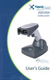
MS7120 Orbit Presentation Laser Scanner IUG - Finn-ID
MS7120 Orbit Presentation Laser Scanner IUG - Finn-ID
MS7120 Orbit Presentation Laser Scanner IUG - Finn-ID
Create successful ePaper yourself
Turn your PDF publications into a flip-book with our unique Google optimized e-Paper software.
<strong>MS7120</strong><br />
<strong>Orbit</strong> ® <strong>Presentation</strong> <strong>Laser</strong> <strong>Scanner</strong><br />
Installation and User’s Guide
Disclaimer<br />
Honeywell International Inc. (“HII”) reserves the right to make changes in<br />
specifications and other information contained in this document without prior<br />
notice, and the reader should in all cases consult HII to determine whether any<br />
such changes have been made. The information in this publication does not<br />
represent a commitment on the part of HII.<br />
HII shall not be liable for technical or editorial errors or omissions contained<br />
herein: nor for incidental or consequential damages resulting from the furnishing,<br />
performance, or use of this manual.<br />
This document contains propriety information that is protected by copyright. All<br />
rights reserved. No part of this document may be photocopied, reproduced, or<br />
translated into another language without the prior written consent of HII.<br />
© 2009 Honeywell International Inc. All rights reserved.<br />
Web Address: www.honeywellaidc.com<br />
Trademarks<br />
Metrologic, MetroSelect, and MetroSet2 are trademarks or registered trademarks<br />
of Metrologic Instruments, Inc. or Honeywell International Inc.<br />
Microsoft, Windows, and Windows 95 are trademarks or registered trademarks of<br />
Microsoft Corporation.<br />
IBM is a trademark of International Business Machines Corporation.<br />
Other product names mentioned in this manual may be trademarks or registered<br />
trademarks of their respective companies and are the property of their respective<br />
owners.<br />
Patents<br />
Please refer to page 34 for a list of patents.
TABLE OF CONTENTS<br />
Introduction<br />
Product Overview ............................................................................................. 1<br />
<strong>Scanner</strong> and Accessories................................................................................. 2<br />
<strong>Scanner</strong> Components....................................................................................... 4<br />
Cable Removal................................................................................................. 4<br />
Caution and Serial Number Labels................................................................... 5<br />
Maintenance..................................................................................................... 5<br />
Mounting Specifications ................................................................................... 6<br />
Installation<br />
RS232, or Light Pen ......................................................................................... 7<br />
RS485 .............................................................................................................. 8<br />
Keyboard Wedge.............................................................................................. 9<br />
Stand-Alone Keyboard Wedge ....................................................................... 10<br />
Full Speed or Low Speed USB....................................................................... 11<br />
<strong>Scanner</strong> Operation<br />
Indicators<br />
Audible ....................................................................................................... 12<br />
Visual ......................................................................................................... 13<br />
Failure ........................................................................................................ 14<br />
Depth of Field Specifications<br />
Normal Scan Zone ..................................................................................... 15<br />
Reduced Scan Zone................................................................................... 15<br />
Depth of Field by Bar Code Element Width<br />
Normal Scan Zone ..................................................................................... 16<br />
Reduced Scan Zone................................................................................... 17<br />
Troubleshooting Guide ....................................................................................... 18<br />
Design Specifications ......................................................................................... 22<br />
Applications and Protocols ................................................................................. 24<br />
ii
TABLE OF CONTENTS<br />
<strong>Scanner</strong> Configuration........................................................................................ 25<br />
Configuration Modes ...................................................................................... 25<br />
Bar Codes .................................................................................................. 25<br />
MetroSet2................................................................................................... 25<br />
Serial Configuration.................................................................................... 25<br />
Upgrading the Firmware..................................................................................... 26<br />
<strong>Scanner</strong> and Cable Terminations<br />
<strong>Scanner</strong> Pinout Connections .......................................................................... 27<br />
Cable Connector Configurations (Host End) .................................................. 28<br />
Regulatory Compliance<br />
Safety ............................................................................................................. 30<br />
EMC ............................................................................................................... 31<br />
Limited Warranty ................................................................................................ 33<br />
Patents ............................................................................................................... 34<br />
Index .................................................................................................................. 35<br />
Customer Support .............................................................................................. 37<br />
Technical Assistance...................................................................................... 37<br />
Product Service and Repair............................................................................ 38<br />
iii
INTRODUCTION<br />
<strong>Orbit</strong> ® is an aggressive, omnidirectional laser bar code scanner ideal for use in<br />
retail, convenience, liquor and specialty stores Designed to be lightweight and<br />
rugged, <strong>Orbit</strong>’s small size makes it ideal for applications where counter space is<br />
limited. The <strong>MS7120</strong> unique contoured shape allows it to be picked-up and used<br />
as a hand-held scanner when scanning large or bulky items.<br />
Key Product Features<br />
Fully Automatic Scanning Operation<br />
Adjustable Scan Head<br />
User-Replaceable Single Cable Interface To Host (Powerlink Compatible)<br />
Seven Beeper Tones<br />
Configurable Depth of Field<br />
Firmware updates are easily loaded into Flash memory<br />
OPOS and JPOS System Compatible<br />
Support For Common Interfaces Including USB (See Table Below)<br />
Easy Bar Code Configuration<br />
ORBIT<br />
MODEL NUMBER<br />
<strong>MS7120</strong>-38<br />
<strong>MS7120</strong>-41<br />
<strong>MS7120</strong>-47<br />
<strong>MS7120</strong>-106<br />
INTERFACE<br />
RS232 Low Speed USB,<br />
Keyboard Emulation Mode or Serial Emulation Mode*<br />
RS232/Light Pen Emulation<br />
Keyboard Wedge,<br />
Stand-Alone Keyboard and RS232 Transmit/Receive<br />
RS485 and Full Speed USB<br />
* Configurable for Keyboard Emulation Mode or Serial Emulation Mode.<br />
Default setting is Keyboard Emulation Mode.<br />
<br />
Applicable for IBM ® Host applications.<br />
1
INTRODUCTION<br />
<strong>Scanner</strong> and Accessories<br />
BASIC KIT COMPONENTS<br />
Part No.<br />
<strong>MS7120</strong><br />
00-02282x<br />
Description<br />
<strong>Orbit</strong> <strong>Presentation</strong> <strong>Laser</strong> Bar Code <strong>Scanner</strong><br />
<strong>MS7120</strong> <strong>Orbit</strong> <strong>Presentation</strong> <strong>Laser</strong> Bar Code <strong>Scanner</strong><br />
Installation and User’s Guide<br />
00-02407x MetroSelect ® Configuration Guide<br />
* Guides also available for download at www.honeywellaidc.com.<br />
OPTIONAL ACCESSORIES<br />
Part No.<br />
Description<br />
AC to DC Power Transformer - Regulated 5.2VDC @ 1A output.<br />
46-00525 90VAC to 255VAC United States, Canada and Japan<br />
46-00526 90VAC to 255VAC Continental European<br />
46-00527 90VAC to 255VAC United Kingdom<br />
46-00528 90VAC to 255VAC Australia<br />
46-00529 90VAC to 255VAC China<br />
46-00530 90VAC to 255VAC India<br />
59-59000x -3<br />
RS232 PowerLink Cable with Built in Power Jack<br />
straight cord, short strain relief<br />
Other items may be ordered for the specific protocol being used. To order additional items,<br />
contact the dealer, distributor or customer service representative.<br />
2
INTRODUCTION<br />
<strong>Scanner</strong> and Accessories<br />
OPTIONAL ACCESSORIES<br />
MVC**<br />
Part No.<br />
Description<br />
RS485 Applications<br />
MVC Cable ±12VDC to +5.2VDC<br />
** Contact a customer service representative for additional information on<br />
the MVC cable series and the host connections available.<br />
59-59002x-3<br />
59-59020x-3<br />
54-54213x-N-3<br />
54-54214x-N-3<br />
59-59235x-N-3<br />
Keyboard Wedge PowerLink Cable<br />
straight cord, short strain relief<br />
Stand Alone Keyboard PowerLink Cable<br />
straight cord, short strain relief<br />
USB Full Speed Cable, Locking Plus-Power Type A<br />
straight cord, short strain relief<br />
USB Full Speed Cable, Locking Plus-Power Type A<br />
straight cord, short strain relief<br />
This cable is for use with full speed<br />
USB (-106) interface only.<br />
USB Low Speed Communication Cable, Type A<br />
straight cord, short strain relief<br />
45-45619 Counter/Wall Mount Kit<br />
Other items may be ordered for the specific protocol being used. To order additional items,<br />
contact the dealer, distributor or customer service representative.<br />
3
INTRODUCTION<br />
<strong>Scanner</strong> Components<br />
ITEM NO<br />
DESCRIPTION<br />
1 White LED (see page 12)<br />
2 Blue LED (see page 12)<br />
3 Red Output Window (<strong>Laser</strong> Aperture)<br />
4 Speaker (see page 12)<br />
5 Pin Hole for Cable Release<br />
6 10-Pin RJ45, Female Socket (see page 28)<br />
7 Adjustable Scan Head, 30°<br />
Figure 1. <strong>Scanner</strong> Components<br />
Cable Removal<br />
1. Locate the small ‘pin-hole’ on the bottom of<br />
the scanner near the cable.<br />
2. Bend an ordinary paperclip into the shape<br />
shown.<br />
3. Insert the paperclip into the small ‘pin-hole’.<br />
4. There will be a faint ‘click’ when the cable<br />
lock is released. Pull gently on the strainrelief<br />
of the PowerLink cable to remove it<br />
from the scanner.<br />
4<br />
Figure 2. Cable Release
INTRODUCTION<br />
Caution and Serial Number Labels<br />
Figure 3. Labeling Locations on the Bottom of the <strong>Scanner</strong> and Examples<br />
Caution<br />
To maintain compliance with applicable standards, all circuits connected to the scanner must<br />
meet the requirements for SELV (Safety Extra Low Voltage) according to EN/IEC 60950-1.<br />
To maintain compliance with standard CSA C22.2 No. 60950-1/UL 60950-1 and norm<br />
EN/IEC 60950-1, the power source should meet applicable performance requirements for a<br />
limited power source.<br />
Maintenance<br />
Smudges and dirt on the unit's window can interfere with the unit's performance.<br />
If the window requires cleaning, use only a mild glass cleaner containing no<br />
ammonia. When cleaning the window, spray the cleaner onto a lint free, nonabrasive<br />
cleaning cloth then gently wipe the window clean.<br />
If the unit's case requires cleaning, use a mild cleaning agent that does not<br />
contain strong oxidizing chemicals. Strong cleaning agents may discolor or<br />
damage the unit's exterior.<br />
5
INTRODUCTION<br />
Mounting Specifications<br />
Optional Wall/Counter Mount<br />
Item Description Qty.<br />
a. Locking Plate, PN 50-50302 1<br />
b. Base Cover, PN 50-50301 1<br />
c. #7 x 1.00" Wood Screw, PN 18-18013 3<br />
d. M3 x 8 mm Flathead Screw, PN 18-18004 4 Figure 4. Kit Components<br />
1. Drill three #39 pilot holes.<br />
Note the position <strong>Orbit</strong> will rest<br />
(see Figure 5). Use the dimensions<br />
provided in Figure 5 or the locking<br />
plate as a template to drill three<br />
#39 pilot holes in the mounting<br />
surface.<br />
Figure 5<br />
2. Attach the locking plate to the wall/counter.<br />
Secure the locking plate to the counter/wall with the three #7 x 1.00" wood<br />
screws provided (see Figure 6).<br />
3. Attach the base plate to the <strong>Orbit</strong>.<br />
Secure the base cover to the bottom of <strong>Orbit</strong> using the four M3 x 8 mm<br />
screws provided (see Figure 7).<br />
4. Mount <strong>Orbit</strong> to the locking plate.<br />
Hold <strong>Orbit</strong> 90° clockwise from the desired position then lower it over the<br />
locking plate until it sits flush to the countertop. Twist <strong>Orbit</strong> counter<br />
clockwise 90° to lock the scanner in place (see Figure 8).<br />
Figure 6<br />
Figure 7<br />
Figure 8<br />
6
INSTALLATION<br />
RS232, Light Pen Emulation<br />
1. Turn off the host device.<br />
2. Plug the male 10-pin RJ45 end<br />
of the PowerLink cable into the<br />
10-pin socket on the <strong>MS7120</strong>.<br />
3. Connect the 9-pin female end of the<br />
PowerLink cable to the host device.<br />
4. Plug the external power supply into the<br />
power jack on the PowerLink cable.<br />
Check the AC input requirements<br />
of the power supply to make sure<br />
the voltage matches the AC outlet.<br />
The outlet must be located near<br />
the equipment and be easily<br />
accessible.<br />
5. Connect AC power to the transformer.<br />
6. Turn on the host device.<br />
Figure 9.<br />
When the scanner first receives power, the blue and white LED will<br />
toggle on and off then the scanner will beep once.<br />
Plugging the scanner into the serial port of the PC does not guarantee<br />
that scanned information will appear at the PC. A software driver and<br />
correct configuration setting are also required for proper<br />
communication to occur.<br />
Powering the <strong>MS7120</strong> directly from the host device can cause<br />
interference with the operation of the scanner or the computer. Not<br />
all computers supply the same current. For this reason, Honeywell<br />
recommends using an external power supply. For additional<br />
information contact a Honeywell customer service representative.<br />
See page 5.<br />
7
INSTALLATION<br />
RS485<br />
1. Turn off the host device.<br />
2. Plug the male 10-pin RJ45 end<br />
of the MVC cable into the<br />
10-pin socket on the <strong>MS7120</strong>.<br />
3. Connect the other end of the MVC<br />
cable to the host device.<br />
4. Turn on the host device.<br />
Figure 10.<br />
When the scanner first receives power, the blue and white LED will<br />
toggle on and off then the scanner will beep once.<br />
Plugging the scanner into the serial port of the PC does not<br />
guarantee that scanned information will appear at the PC. A software<br />
driver and correct configuration setting are also required for proper<br />
communication to occur.<br />
8
INSTALLATION<br />
Keyboard Wedge<br />
1. Turn off the host device.<br />
2. Plug the male 10-pin RJ45 end of the<br />
PowerLink cable into the 10-pin<br />
socket on the <strong>MS7120</strong>.<br />
3. Disconnect the keyboard from the<br />
host device.<br />
4. Connect the “Y” end of the PowerLink<br />
cable to the keyboard and the<br />
keyboard port on the host PC. If<br />
necessary use the male/female<br />
adapter cable supplied with the<br />
scanner for proper connections.<br />
5. Plug the external power supply into the<br />
power jack on the PowerLink cable.<br />
Check the AC input requirements<br />
of the power supply to make sure<br />
the voltage matches the AC<br />
outlet. The outlet must be<br />
located near the equipment and<br />
be easily accessible. Figure 11.<br />
6. Connect AC power to the transformer.<br />
7. Turn on the host device.<br />
When the scanner first receives power, the blue and white LED will<br />
toggle on and off then the scanner will beep once.<br />
Powering the <strong>MS7120</strong> directly from the host device can sometimes<br />
cause interference with the operation of the scanner or the computer.<br />
Not all computers supply the same current through the keyboard port.<br />
For this reason, Honeywell recommends using an external power<br />
supply. For additional information contact a customer service<br />
representative.<br />
See page 5.<br />
9
INSTALLATION<br />
Stand-Alone Keyboard<br />
1. Turn off the host device.<br />
2. Plug the male 10-pin RJ45 end<br />
of the PowerLink cable into the<br />
10-pin socket on the <strong>MS7120</strong>.<br />
3. Connect the other end of the<br />
PowerLink cable to the keyboard<br />
port on the host device.<br />
4. Plug the external power supply into<br />
the power jack on the PowerLink<br />
cable.<br />
Check the AC input<br />
requirements of the power<br />
supply to make sure the<br />
voltage matches the AC<br />
outlet. The outlet must be<br />
located near the equipment<br />
and be easily accessible.<br />
5. Connect AC power to the transformer. Figure 12.<br />
6. Turn on the host device.<br />
When the scanner first receives power, the blue and white LED will<br />
toggle on and off then the scanner will beep once.<br />
Powering the <strong>MS7120</strong> directly from the host device can sometimes<br />
cause interference with the operation of the scanner or the computer.<br />
Not all computers supply the same current through the keyboard port.<br />
For this reason, Honeywell recommends using an external power<br />
supply. For additional information contact a customer service<br />
representative.<br />
See page 5.<br />
10
INSTALLATION<br />
Full Speed or Low Speed USB<br />
1. Turn off the host device.<br />
2. Plug the male 10-pin RJ45 end of<br />
the USB cable into the 10-pin<br />
socket on the <strong>MS7120</strong>.<br />
3. Plug the other end of the USB<br />
interface cable into the host<br />
device’s USB port.<br />
4. Turn on the host device.<br />
When the scanner first receives<br />
power, the blue and white LED<br />
will toggle on and off then the<br />
scanner will beep once.<br />
Figure 13.<br />
As a default, the <strong>MS7120</strong>-38 leaves the factory with USB Keyboard<br />
Emulation Mode enabled. Scan the following bar code to configure<br />
the <strong>MS7120</strong>-38 for USB Serial Emulation Mode.<br />
³ 3 1 6 4 6 0<br />
Plugging the scanner into the USB port of the PC does not guarantee<br />
that scanned information will appear at the PC. A software driver and<br />
the correct configuration settings are also required for proper<br />
communication to occur.<br />
For Previous User’s of the MX009<br />
In order for the new integrated USB <strong>Orbit</strong>* to function with the same<br />
serial emulation driver as the old external USB <strong>Orbit</strong>, scan the<br />
following bar code.<br />
* Rev L <strong>Orbit</strong>s or above.<br />
³ 3 1 6 4 7 0<br />
11
SCANNER OPERATION<br />
Audible Indicators<br />
When the <strong>MS7120</strong> is in operation, it provides audible feedback to indicate the<br />
status of the scanner. Eight settings are available for the tone of the beep<br />
(normal, six alternate tones and no tone). For instructions on how to change the<br />
tone of the beeper, refer to the MetroSelect Configuration Guide (00-02407).<br />
One Beep<br />
When the scanner first receives power the blue and white LED will toggle on<br />
and off. The scanner will beep once, then the LEDs will stop toggling and the<br />
blue LED will remain on to indicate the scanner is ready to scan.<br />
When the scanner successfully reads a bar code, the white LED will flash and<br />
the scanner will emit a beep*. If the scanner does not beep once and the white<br />
light does not flash, then the bar code has not been successfully read.<br />
Razzberry Tone<br />
This is a failure indicator. Refer to Failure Mode Indicators on page 14.<br />
When in configuration mode, a razzberry tone indicates that an invalid bar code<br />
has been scanned.<br />
Three Beeps - During Operation<br />
When entering configuration mode † the scanner will beep three times and the<br />
white and blue LED will start to toggle on and off. The blue LED and the white<br />
LED will toggle on and off until the scanner exits the configuration mode.<br />
Upon exiting configuration mode † , the white LED will flash three times and the<br />
scanner will beep three times. The blue LED will then stay on indicating the<br />
scanner is ready to scan.<br />
When using one-code-configuring, the scanner will emit a unique beep three<br />
times after scanning. This indicates that the single configuration bar code has<br />
successfully configured the scanner.<br />
Three beeps* can also indicate a communications timeout during normal<br />
scanning mode.<br />
Three Beeps - On Power Up<br />
This is a failure indicator. Refer to Failure Mode Indicators on page 14.<br />
* This feature is configuration dependent. Refer to the MetroSelect Configuration Guide<br />
to enable this feature.<br />
† Refer to the Multi-Code Configuration Method in the MetroSelect Configuration Guide.<br />
12
SCANNER OPERATION<br />
Visual Indicators<br />
The <strong>MS7120</strong> is equipped with a blue and a white LED that indicates the<br />
scanner’s state and the status of the current scan when the unit is in operation.<br />
No LEDs<br />
Figure 14. LED Location<br />
The LEDs will not be illuminated if the scanner is not receiving power from the<br />
host or transformer.<br />
Steady Blue<br />
When the laser is active, the blue LED is illuminated. The blue LED will remain<br />
on until the laser is deactivated.<br />
During the power save mode, the laser will turn on and off. During this period,<br />
the blue LED will remain on.<br />
Steady Blue and Single White Flash<br />
When the scanner successfully reads a bar code, the white LED will flash and<br />
the scanner will beep once. If the white LED does not flash or the scanner<br />
does not beep once, then the bar code has not been successfully read.<br />
Steady White and Blue<br />
After a successful scan, the scanner transmits the data to the host device.<br />
Some communication modes require that the host inform the scanner when<br />
data is ready to be received. If the host is not ready to accept the information,<br />
the scanner’s white LED will remain on until the data can be transmitted.<br />
Alternating (Toggling) Blue and White<br />
This indicates the scanner is in configuration mode. A razzberry tone indicates<br />
that an invalid bar code has been scanned in this mode.<br />
13
SCANNER OPERATION<br />
Failure Mode Indicators<br />
Flashing Blue with One Razzberry Tone<br />
This indicates that the scanner has experienced a laser subsystem failure.<br />
Return the unit to an authorized service center for repair.<br />
Synchronized Flashing of Blue and White with Two Razzberry Tones<br />
This indicates that the scanner has experienced a motor failure. Return the unit<br />
to an authorized service center for repair.<br />
Three Beeps - On Power Up<br />
If the scanner beeps three times on power up, then the nonvolatile memory<br />
that holds the scanner configuration may have failed. First, check the<br />
scanner’s settings. Then, try to re-configure the scanner. If the problem<br />
persists return the unit to an authorized service center for repair.<br />
14
SCANNER OPERATION<br />
Depth of Field Specifications*<br />
Normal Scan Zone<br />
Specifications are based on a 0.33 mm (13 mil) bar code.<br />
Figure 15. <strong>MS7120</strong> Normal Depth of Field<br />
Reduced Scan Zone<br />
Specifications are based on a 0.33 mm (13 mil) bar code.<br />
Figure 16. <strong>MS7120</strong> Reduced Depth of Field<br />
* All specifications are subject to change without notice.<br />
15
SCANNER OPERATION<br />
Depth of Field by Bar Code Element Width*<br />
Normal Scan Zone<br />
MINIMUM BAR CODE ELEMENT W<strong>ID</strong>TH<br />
A B C D E F G H J K<br />
mm .13 - - - .19 - .25 .33 - .66<br />
mils 5.2 - - - 7.5 - 10 13 - 26<br />
Figure 17. Normal Scan Zone by Bar Code Element Width<br />
* All specifications are subject to change without notice.<br />
16
SCANNER OPERATION<br />
Depth of Field by Bar Code Element Width*<br />
Reduced Scan Zone<br />
MINIMUM BAR CODE ELEMENT W<strong>ID</strong>TH<br />
A B C D E F G H J K<br />
mm - .15 - - .19 - .25 .33 - .66<br />
mils - 5.7 - - 7.5 - 10 13 - 26<br />
Figure 18. Reduced Scan Zone by Bar Code Element Width<br />
* All specifications are subject to change without notice.<br />
17
TROUBLESHOOTING GU<strong>ID</strong>E<br />
The following guide is for reference purposes only. Contact a customer service<br />
representative to preserve the limited warranty terms on page 33.<br />
Symptoms Possible Cause(s) Solution<br />
All Interfaces<br />
During power<br />
up the unit<br />
beeps three<br />
times.<br />
There is a non-volatile<br />
RAM failure.<br />
Contact a customer service<br />
representative.<br />
During power<br />
up the unit<br />
razzes once<br />
and the blue<br />
LED flashes.<br />
There is a VLD failure.<br />
Contact a customer service<br />
representative.<br />
During power<br />
up the unit<br />
razzes twice<br />
and both LEDs<br />
flash in unison.<br />
There is a scanner<br />
motor failure.<br />
Contact a customer service<br />
representative.<br />
The unit has no<br />
LEDs, beeper<br />
or motor spin.<br />
No power is being<br />
supplied to the<br />
scanner.<br />
Check the transformer, outlet<br />
and power strip. Make sure the<br />
cable is plugged into the<br />
scanner.<br />
The unit has no<br />
LEDs and / or<br />
beeper.<br />
No power is being<br />
supplied to the<br />
scanner from host.<br />
Some host systems cannot<br />
supply enough current to power<br />
the <strong>Orbit</strong>. Use the power supply<br />
included with the scanner.<br />
The unit powers The beeper is disabled. Enable the beeper.<br />
up but does not<br />
beep. No tone is selected. Select a tone.<br />
18
TROUBLESHOOTING GU<strong>ID</strong>E<br />
Symptoms Possible Cause(s) Solution<br />
All Interfaces<br />
The unit powers<br />
up but does not<br />
scan and/or<br />
beep.<br />
The unit is trying to<br />
scan a particular<br />
symbology that is not<br />
enabled.<br />
The scanner has been<br />
configured for a<br />
character length lock,<br />
or a minimum length<br />
and bar code being<br />
scanned does not<br />
satisfy the configured<br />
criteria.<br />
UPC/EAN, Code 39, Interleaved<br />
2 of 5, Code 93, Code 128 and<br />
Codabar are enabled by default.<br />
Verify that the type of bar code<br />
being read has been selected<br />
Verify that the bar code that is<br />
being scanned falls into the<br />
criteria.<br />
Typical of Non-UPC/EAN codes.<br />
The scanner defaults to a<br />
minimum of four character bar<br />
code.<br />
The unit scans<br />
a bar code, but<br />
locks up after<br />
the first scan<br />
(the white LED<br />
stays on).<br />
The scanner is<br />
configured to support<br />
some form of host<br />
handshaking but is not<br />
receiving the signal.<br />
If the scanner is setup to support<br />
ACK/NAK, RTS/CTS,<br />
XON/XOFF or D/E, verify that<br />
the host cable and host are<br />
supporting the handshaking<br />
properly.<br />
The unit scans<br />
but the data<br />
transmitted to<br />
the host is<br />
incorrect.<br />
The scanner’s data<br />
format does not match<br />
the host system<br />
requirements.<br />
Verify that the scanner’s data<br />
format matches the format<br />
required by the host.<br />
Make sure that the scanner is<br />
connected to the proper host<br />
port.<br />
There are<br />
multiple scans<br />
upon<br />
presentation of<br />
code.<br />
The same symbol<br />
timeout is set too<br />
short.<br />
Adjust the same symbol timeout<br />
for a longer time increment.<br />
19
TROUBLESHOOTING GU<strong>ID</strong>E<br />
Symptoms Possible Cause(s) Solution<br />
All Interfaces<br />
<strong>Scanner</strong> beeps<br />
at some bar<br />
codes and NOT<br />
for others of the<br />
same bar code<br />
symbology.<br />
The bar code may<br />
have been printed<br />
incorrectly.<br />
The scanner is not<br />
configured correctly for<br />
the type of bar code.<br />
The minimum symbol<br />
length setting does not<br />
work with the bar code.<br />
Check if it is a check digit,<br />
character or border problem.<br />
Check if check digits are set<br />
properly.<br />
Check if the correct minimum<br />
symbol length is set.<br />
RS232 Only<br />
The unit powers<br />
up OK and<br />
scans OK but<br />
does not<br />
communicate<br />
properly to the<br />
host.<br />
The com port at the<br />
host is not working or<br />
is not configured<br />
properly.<br />
The cable is not<br />
connected to the<br />
proper com port.<br />
The com port is not<br />
operating properly.<br />
Check to make sure that the<br />
baud rate and parity of the<br />
scanner and the communication<br />
port match and that the program<br />
is looking for RS232 data.<br />
20
TROUBLESHOOTING GU<strong>ID</strong>E<br />
Symptoms Possible Cause(s) Solution<br />
RS232 Only<br />
The host is<br />
receiving data<br />
but the data does<br />
not look correct.<br />
The scanner and host<br />
may not be configured<br />
for the same interface.<br />
Check that the scanner and the<br />
host are configured for the same<br />
interface.<br />
Characters are<br />
being dropped.<br />
The inter character<br />
delay needs to be<br />
added to the<br />
transmitted output.<br />
Add some inter-character delay to<br />
the transmitted output by using<br />
the MetroSelect Configuration<br />
Guide (PN 00-02407).<br />
Keyboard Wedge Only<br />
The unit scans<br />
the bar code<br />
but there is no<br />
data.<br />
The unit may not be<br />
configured correctly.<br />
Make sure the scanner is<br />
configured for the appropriate<br />
mode.<br />
The unit scans<br />
but the data is<br />
not correct.<br />
The unit is not<br />
transmitting<br />
each character.<br />
Alpha characters<br />
show as lower<br />
case.<br />
Everything<br />
works except<br />
for a couple of<br />
characters.<br />
The unit may not be<br />
configured correctly.<br />
The unit may not be<br />
configured correctly.<br />
The computer is in<br />
caps lock mode.<br />
These characters may<br />
not be supported by<br />
the current country’s<br />
key, look up table.<br />
Make sure that the proper PC<br />
type (ie. AT or PS2 ) is selected.<br />
Verify correct country code and<br />
data formatting are selected.<br />
Adjust the inter-scan delay.<br />
Increase the inter-scan code<br />
delay setting. Adjust whether<br />
the F0 break is transmitted. It<br />
may be necessary to try both<br />
settings.<br />
Enable caps lock detect setting<br />
of the scanner to detect whether<br />
the PC is operating in caps lock.<br />
Try operating the scanner<br />
in Alt Mode.<br />
21
DESIGN SPECIFICATIONS<br />
<strong>MS7120</strong><br />
Operational<br />
Light Source:<br />
<strong>Laser</strong> Power:<br />
Visible <strong>Laser</strong> Diode (VLD) @ 650 nm<br />
Less than 1 mW average<br />
Normal Depth of Field:<br />
Reduced Depth of Field:<br />
Scan Speed:<br />
0 mm – 215 mm<br />
0 mm – 190 mm<br />
1120 scan lines per second<br />
0.33 mm (13 mil) bar code<br />
No. of Scan Lines: 20<br />
Motor Speed:<br />
Min Bar Width:<br />
Decode Capability:<br />
System Interfaces:<br />
Print Contrast:<br />
No. Characters Read:<br />
Beeper Operation:<br />
Indicators (LED):<br />
3360 RPM<br />
0.13 mm (5.0 mil)<br />
All standard 1-D bar codes including GS1 DataBar,<br />
GS1 DataBar - Expanded, and GS1 DataBar Limited<br />
RS232, Keyboard Wedge, Stand-Alone Keyboard, Light Pen<br />
Emulation, RS485, USB (low speed and full speed)<br />
35% minimum reflectance difference<br />
Up to 80 data characters<br />
Maximum number will vary based on symbology and density.<br />
7 tones or no beep<br />
Blue = laser on, ready to scan<br />
White = good read, decoding<br />
Mechanical<br />
Width: Base - 102 mm (4.0") Orb - 80 mm (3.1")<br />
Depth : 105 mm (4.1")<br />
Height: 150 mm (5.9")<br />
Weight: 14.5 oz (410 g)<br />
Orb Tilt:<br />
30° Vertical<br />
Specifications subject to change without notice.<br />
22
DESIGN SPECIFICATIONS<br />
<strong>MS7120</strong><br />
Electrical<br />
Voltage Supply: 5VDC ± 0.25V<br />
Operating Power:<br />
Standby Power:<br />
Operating Current:<br />
Standby Current:<br />
DC Transformers:<br />
0.9 W<br />
0.85 W<br />
180 mA typical at 5VDC<br />
170 mA typical at 5VDC<br />
Class II; 5.2VDC @ 1A<br />
For regulatory compliance information, see pages 30 - 32.<br />
Environmental<br />
Operating Temperature:<br />
Storage Temperature:<br />
Humidity:<br />
Contaminants:<br />
Ventilation:<br />
-20°C to 40°C (-4°F to 104°F)<br />
-40°C to 60°C (-40°F to 140°F)<br />
5% to 95% relative humidity, non-condensing<br />
Sealed to resist airborne particulate contaminants<br />
None required<br />
Specifications subject to change without notice.<br />
23
APPLICATIONS AND PROTOCOLS<br />
The model number on each scanner includes the scanner number and factory<br />
default communications protocol.<br />
SCANNER<br />
VERSION<br />
<strong>ID</strong>ENTIFIER<br />
38<br />
COMMUNICATION PROTOCOL(S)<br />
RS232 Low Speed USB,<br />
Keyboard Emulation or Serial Emulation<br />
<strong>MS7120</strong><br />
41 Full RS232C/Light Pen Emulation<br />
47<br />
Keyboard Wedge, Stand-Alone Keyboard and<br />
RS232 Transmit/Receive<br />
106 RS485 and Full Speed USB<br />
The <strong>MS7120</strong> scanner with built-in PC Keyboard Wedge Interface is designed to<br />
be used for keyboard emulation only. Many RS232 configurable<br />
functions (e.g. formatting) available in other Honeywell scanners are also<br />
available as keyboard wedge functions.<br />
The following are the most important selectable options specific to the keyboard<br />
wedge.<br />
Keyboard Type<br />
** AT (includes IBM ® PS2 models 50, 55, 60, 80)<br />
IBM PS2 (includes models 30, 70, 8556)<br />
Keyboard Country Type<br />
USA ** Italian Swiss<br />
Belgium Japanese Sweden/Finland<br />
French Russian Cryillic Turkish<br />
German Slovenian United Kingdom<br />
Hungarian Spanish<br />
** Default setting. Refer to the MetroSelect ® Configuration Guide<br />
(PN 00-02407) or MetroSet2’s help files for information on how to change the<br />
default settings.<br />
24
SCANNER CONFIGURATION<br />
CONFIGURATION MODES<br />
The <strong>MS7120</strong>* Series scanner has three modes of configuration.<br />
<br />
<br />
<br />
Bar Codes<br />
The <strong>MS7120</strong> can be configured by scanning the bar codes located in the<br />
MetroSelect ® Configuration Guide. This manual is available for download at<br />
www.honeywellaidc.com.<br />
MetroSet2<br />
This user-friendly Windows ® -based configuration program allows you to<br />
simply ‘point-and-click’ at the desired scanner options. MetroSet2 is<br />
available for download at www.honeywellaidc.com.<br />
Serial Configuration<br />
This mode of configuration is ideal for OEM applications. Serial<br />
programming mode gives the end-user the ability to send a series of<br />
commands using the serial port of the host system. The commands are<br />
equivalent to the numerical values of the bar codes located in the<br />
MetroSelect Configuration Guide.<br />
* Revision L or later.<br />
25
UPGRADING THE FIRMWARE<br />
The <strong>MS7120</strong> is part of Honeywell’s line of scanners with flash upgradeable<br />
firmware. The upgrade process requires, a new firmware file supplied to the<br />
customer by a customer service representative and Honeywell’s MetroSet2<br />
software . A personal computer running Windows 95 or greater with an<br />
available RS232 serial or USB port is required to complete the upgrade.<br />
PowerLink Cable #54-54014 is required when using RS232 for the<br />
upgrade process. This cable can be ordered by a customer service<br />
representative. Do not use the standard cable supplied with keyboard<br />
wedge or RS485 scanner interface kits. If using USB for the upgrade<br />
process, the standard USB cable provided with the scanner can be<br />
used.<br />
To upgrade the firmware in the <strong>MS7120</strong>:<br />
1. Plug the scanner into a serial communication port on the host system.<br />
2. Start the MetroSet2 software.<br />
3. Click on the plus sign (+) next to POS <strong>Scanner</strong>s to expand the supported<br />
scanner list.<br />
4. Choose the <strong>MS7120</strong> <strong>Orbit</strong> or <strong>Orbit</strong> (L+)* from the list.<br />
5. Click on the Configure <strong>Orbit</strong>/7120 (L+)* <strong>Scanner</strong> button.<br />
6. Choose Flash Utility from the options list located on the left side of the<br />
screen.<br />
7. Click on the Open File button in the Flash Utility window.<br />
8. Locate and open the flash upgrade file supplied.<br />
9. Select the COM port that the scanner is connected to on the host system.<br />
10. Verify the settings listed in the Flash Utility window.<br />
11. Click on the Flash <strong>Scanner</strong> button to begin the flash upgrade.<br />
12. A message will appear on the screen when the upgrade is complete.<br />
<br />
<br />
See Customer Support on page 37.<br />
MetroSet2 is available for download, at no additional cost, from<br />
www.honeywellaidc.com<br />
* Revision L or later.<br />
26
SCANNER AND CABLE TERMINATIONS<br />
<strong>Scanner</strong> Pinout Connections<br />
The <strong>MS7120</strong> scanner interfaces terminate to a 10-pin modular socket. The serial<br />
number label indicates the interface enabled when the scanner is shipped from<br />
the factory.<br />
<strong>MS7120</strong>-47 Keyboard Wedge<br />
and Stand-Alone Keyboard<br />
Figure 19.<br />
<strong>MS7120</strong>-41<br />
RS232C and Light Pen Emulation<br />
Pin Function Pin Function<br />
1 Ground 1 Ground<br />
2 RS232 Transmit Output 2 RS232 Transmit Output<br />
3 RS232 Receive Input 3 RS232 Receive Input<br />
4 PC Data 4 RTS Output<br />
5 PC Clock 5 CTS Input<br />
6 KB Clock 6 DTR Input/LTPN Source<br />
7 PC +5V 7 Reserved<br />
8 KB Data 8 LTPN Data<br />
9 +5VDC 9 +5VDC<br />
10 Shield Ground 10 Shield Ground<br />
<strong>MS7120</strong>-106<br />
RS485 and Full Speed USB<br />
<strong>MS7120</strong>-38<br />
RS232 Low Speed USB<br />
Pin Function Pin Function<br />
1 Ground 1 Ground<br />
2 RS232 Transmit Output 2 RS232 Transmit Output<br />
3 RS232 Receive Input 3 RS232 Receive Input<br />
4 IBM A+ 4 RTS Output<br />
5 IBM B- 5 CTS Input<br />
6 USB D+ 6 D+<br />
7 USB +V 7 V USB<br />
8 USB D- 8 D-<br />
9 +5VDC 9 +5VDC<br />
10 Shield Ground 10 Shield Ground<br />
27
SCANNER AND CABLE TERMINATIONS<br />
Cable Connector Configurations (Host End)<br />
Pin<br />
“Standard” PowerLink Cable<br />
PN 59-59000x -3 straight<br />
1 Shield Ground<br />
Function<br />
2 RS232 Transmit Output<br />
3 RS232 Receive Input<br />
4 DTR Input/Light Pen Source<br />
5 Power/Signal Ground<br />
6 Light Pen Data<br />
7 CTS Input<br />
9-Pin D-Type Connector<br />
8 RTS Output<br />
9 +5VDC<br />
USB Power/Communication Cable<br />
PN 54-54213x-N-3,<br />
54-54214x-N-3 or 59-59235x-N-3<br />
Pin<br />
Function<br />
1 PC +5V/V_USB<br />
2 D-<br />
3 D+<br />
4 Ground<br />
Shield Shield<br />
Locking, Type A<br />
PN 54-54213x-N-3 or<br />
PN 54-54214x-N-3<br />
Non-Locking, Type A<br />
PN 54-54214x-N-3<br />
Stand Alone Keyboard PowerLink<br />
Cable PN 59-59020x-3<br />
Pin<br />
1 PC Data<br />
2 No Connect<br />
3 Power Ground<br />
Function<br />
4 +5VDC PC Power to KB<br />
5 PC Clock<br />
6 No Connect<br />
6-Pin Male Mini-DIN Connector<br />
28
SCANNER AND CABLE TERMINATIONS<br />
Cable Connector Configurations (Host End)<br />
Keyboard Wedge PowerLink Cable<br />
PN 59-59002x -3<br />
Pin<br />
Function<br />
1 Keyboard Clock<br />
2 Keyboard Data<br />
3 No Connect<br />
4 Power Ground<br />
5 +5 Volts DC<br />
Pin Function<br />
1 PC Data<br />
2 No Connect<br />
3 Power Ground<br />
4 +5 Volts DC<br />
5 PC Clock<br />
6 No Connect<br />
5-Pin DIN, Female<br />
6-Pin DIN, Male<br />
Honeywell will supply an adapter cable with a 5-pin DIN male connector on one<br />
end and a 6-pin mini DIN female connector on the other. According to the<br />
termination required, connect the appropriate end of the adapter cable to the<br />
PowerLink cable, leaving the necessary termination exposed for connecting to<br />
the keyboard and the keyboard port on the PC.<br />
Keyboard Wedge Adapter Cable<br />
Pin Function<br />
1 PC Clock<br />
2 PC Data<br />
3 No Connect<br />
4 Power Ground<br />
5 +5 Volts DC<br />
Pin Function<br />
1 Keyboard Data<br />
2 No Connect<br />
3 Power Ground<br />
4 +5 Volts DC<br />
5 Keyboard Clock<br />
6 No Connect<br />
5-Pin DIN, Male<br />
6-pin Mini DIN, Female<br />
29
REGULATORY COMPLIANCE<br />
Safety<br />
ITE Equipment<br />
IEC 60950-1, EN 60950-1<br />
<strong>Laser</strong><br />
<strong>Laser</strong> Class 1: IEC 60825-1:1993+A1+A2,<br />
EN 60825-1:1994+A1+A2<br />
Caution<br />
Use of controls or adjustments or performance of procedures other than those specified<br />
herein may result in hazardous laser light exposure. Under no circumstances should the<br />
customer attempt to service the laser scanner. Never attempt to look at the laser beam,<br />
even if the scanner appears to be nonfunctional. Never open the scanner in an attempt to<br />
look into the device. Doing so could result in hazardous laser light exposure. The use of<br />
optical instruments with the laser equipment will increase eye hazard.<br />
Atención<br />
La modificación de los procedimientos, o la utilización de controles o ajustes distintos de<br />
los especificados aquí, pueden provocar una luz de láser peligrosa. Bajo ninguna<br />
circunstancia el usuario deberá realizar el mantenimiento del láser del escáner. Ni intentar<br />
mirar al haz del láser incluso cuando este no esté operativo. Tampoco deberá abrir el<br />
escáner para examinar el aparato. El hacerlo puede conllevar una exposición peligrosa a<br />
la luz de láser. El uso de instrumentos ópticos con el equipo láser puede incrementar el<br />
riesgo para la vista.<br />
Attention<br />
L'emploi de commandes, réglages ou procédés autres que ceux décrits ici peut entraîner<br />
de graves irradiations. Le client ne doit en aucun cas essayer d'entretenir lui-même le<br />
scanner ou le laser. Ne regardez jamais directement le rayon laser, même si vous croyez<br />
que le scanner est inactif. N'ouvrez jamais le scanner pour regarder dans l'appareil. Ce<br />
faisant, vous vous exposez à une rayonnement laser qú êst hazardous. L'emploi<br />
d'appareils optiques avec cet équipement laser augmente le risque d'endommagement de<br />
la vision.<br />
Achtung<br />
Die Verwendung anderer als der hier beschriebenen Steuerungen, Einstellungen oder<br />
Verfahren kann eine gefährliche <strong>Laser</strong>strahlung hervorrufen. Der Kunde sollte unter keinen<br />
Umständen versuchen, den <strong>Laser</strong>-<strong>Scanner</strong> selbst zu warten. Sehen Sie niemals in den<br />
<strong>Laser</strong>strahl, selbst wenn Sie glauben, daß der <strong>Scanner</strong> nicht aktiv ist. Öffnen Sie niemals<br />
den <strong>Scanner</strong>, um in das Gerät hineinzusehen. Wenn Sie dies tun, können Sie sich einer<br />
gefährlichen <strong>Laser</strong>strahlung aussetzen. Der Einsatz optischer Geräte mit dieser<br />
<strong>Laser</strong>ausrüstung erhöht das Risiko einer Sehschädigung.<br />
Attenzione<br />
L’utilizzo di sistemi di controllo, di regolazioni o di procedimenti diversi da quelli descritti nel<br />
presente Manuale può provocare delle esposizioni a raggi laser rischiose. Il cliente non<br />
deve assolutamente tentare di riparare egli stesso lo scanner laser. Non guardate mai il<br />
raggio laser, anche se credete che lo scanner non sia attivo. Non aprite mai lo scanner per<br />
guardare dentro l’apparecchio. Facendolo potete esporVi ad una esposizione laser<br />
rischiosa. L’uso di apparecchi ottici, equipaggiati con raggi laser, aumenta il rischio di<br />
danni alla vista..<br />
30
REGULATORY COMPLIANCE<br />
EMC<br />
Emissions: FCC Part 15, ICES-003, CISPR 22, EN 55022<br />
Immunity: CISPR 24, EN 55024<br />
Note: Immunity performance is not guaranteed for scanner cables greater than 3 meters<br />
in length when fully extended.<br />
Changes or modifications not expressly approved by the party responsible for compliance<br />
could void the user’s authority to operate the equipment.<br />
Class A Devices<br />
The following is applicable when the scanner cable is greater in length than 3<br />
meters (9.8 feet) when fully extended:<br />
Les instructions ci-dessous s’appliquent aux cables de scanner dépassant 3<br />
métres (9.8 pieds) de long en extension maximale:<br />
Folgendes trifft zu, wenn das <strong>Scanner</strong>kabel länger als 3 Meter ist:<br />
This equipment has been tested and found to comply with limits for a Class A digital<br />
device, pursuant to part 15 of the FCC Rules. These limits are designed to provide<br />
reasonable protection against harmful interference when the equipment is operated in a<br />
commercial environment. This equipment generates, uses and can radiate radio<br />
frequency energy and, if not installed and used in accordance with the instruction manual,<br />
may cause harmful interference to radio communications. Operation of this equipment in<br />
a residential area is likely to cause harmful interference, in which case the user will be<br />
required to correct the interference at their own expense. Any unauthorized changes or<br />
modifications to this equipment could void the user’s authority to operate this device.<br />
This device complies with part 15 of the FCC Rules. Operation is subject to the following<br />
two conditions: (1) This device may not cause harmful interference, and (2) this device<br />
must accept any interference received, including interference that may cause undesired<br />
operation.<br />
Notice<br />
This Class A digital apparatus complies with Canadian ICES-003.<br />
Remarque<br />
Cet appareil numérique de classe A est conforme à la norme canadienne NMB-003.<br />
European Standard<br />
Warning<br />
This is a class A product. In a domestic environment this product may cause radio<br />
interference in which case the user may be required to take adequate measures.<br />
Funkstöreigenschaften nach EN55022:1998<br />
Warnung!<br />
Dies ist eine Einrichtung der Klasse A. Diese Einrichtung kann im Wohnbereich<br />
Funkstörungen verursachen. In diesem Fall kann vom Betreiber verlangt werden,<br />
angemessene Massnahmen durchzuführen.<br />
31
REGULATORY COMPLIANCE<br />
Standard Europeo<br />
Attenzione<br />
Questo e’ un prodotto di classe A. Se usato in vicinanza di residenze private potrebbe<br />
causare interferenze radio che potrebbero richiedere all’utilizzatore opportune misure.<br />
Attention<br />
Ce produit est de classe “A”. Dans un environnement domestique, ce produit peut être la<br />
cause d’interférences radio. Dans ce cas l’utiliseteur peut être amené à predre les mesures<br />
adéquates.<br />
EMC<br />
Changes or modifications not expressly approved by the party responsible for compliance<br />
could void the user’s authority to operate the equipment.<br />
Class B Devices<br />
The following is applicable when the scanner cable is less than 3 meters (9.8 feet) in<br />
length when fully extended:<br />
Les instructions ci-dessous s’appliquent aux cables de scanner ne dépassant pas 3<br />
métres (9.8 pieds) de long en extension maximale:<br />
Folgendes trifft zu, wenn das <strong>Scanner</strong>kabel kürzer als 3 Meter ist:<br />
This device complies with Part 15 of the FCC Rules. Operation is subject to the following<br />
two conditions: (1) This device may not cause harmful interference, and (2) this device<br />
must accept any interference received, including interference that may cause undesired<br />
operation.<br />
This equipment has been tested and found to comply with the limits for a Class B digital<br />
device, pursuant to Part 15 of the FCC rules. These limits are designed to provide<br />
reasonable protection against harmful interference in a residential installation. This<br />
equipment generates, uses and can radiate radio frequency energy and, if not installed<br />
and used in accordance with the instructions, may cause harmful interference to radio<br />
communications. However, there is no guarantee that interference will not occur in a<br />
particular installation. If this equipment does cause harmful interference to radio or<br />
television reception, which can be determined by turning the equipment off and on, the<br />
user is encouraged to try to correct the interference by one or more of the following<br />
measures:<br />
Reorient or relocate the receiving antenna<br />
Increase the separation between the equipment and receiver<br />
Connect the equipment into an outlet on a circuit different from that to which the<br />
receiver is connected<br />
Consult the dealer or an experienced radio/TV technician for help<br />
Notice<br />
This Class B digital apparatus complies with Canadian ICES-003.<br />
Remarque<br />
Cet appareil numérique de classe B est conforme à la norme canadienne NMB-003.<br />
32
LIMITED WARRANTY<br />
Honeywell International Inc. ("HII") warrants its products and optional accessories to be<br />
free from defects in materials and workmanship and to conform to HII’s published<br />
specifications applicable to the products purchased at the time of shipment. This warranty<br />
does not cover any HII product which is (i) improperly installed or used; (ii) damaged by<br />
accident or negligence, including failure to follow the proper maintenance, service, and<br />
cleaning schedule; or (iii) damaged as a result of (A) modification or alteration by the<br />
purchaser or other party, (B) excessive voltage or current supplied to or drawn from the<br />
interface connections, (C) static electricity or electro-static discharge, (D) operation under<br />
conditions beyond the specified operating parameters, or (E) repair or service of the<br />
product by anyone other than HII or its authorized representatives.<br />
This warranty shall extend from the time of shipment for the duration published by HII for<br />
the product at the time of purchase ("Warranty Period"). Any defective product must be<br />
returned (at purchaser’s expense) during the Warranty Period to HII factory or authorized<br />
service center for inspection. No product will be accepted by HII without a Return Materials<br />
Authorization, which may be obtained by contacting HII. In the event that the product is<br />
returned to HII or its authorized service center within the Warranty Period and HII<br />
determines to its satisfaction that the product is defective due to defects in materials or<br />
workmanship, HII, at its sole option, will either repair or replace the product without charge,<br />
except for return shipping to HII.<br />
EXCEPT AS MAY BE OTHERWISE PROV<strong>ID</strong>ED BY APPLICABLE LAW, THE<br />
FOREGOING WARRANTY IS IN LIEU OF ALL OTHER COVENANTS OR WARRANTIES,<br />
EITHER EXPRESSED OR IMPLIED, ORAL OR WRITTEN, INCLUDING, WITHOUT<br />
LIMITATION, ANY IMPLIED WARRANTIES OF MERCHANTABILITY OR FITNESS FOR A<br />
PARTICULAR PURPOSE, OR NON-INFRINGEMENT.<br />
HII’S RESPONSIBILITY AND PURCHASER’S EXCLUSIVE REMEDY UNDER THIS<br />
WARRANTY IS LIMITED TO THE REPAIR OR REPLACEMENT OF THE DEFECTIVE<br />
PRODUCT WITH NEW OR REFURBISHED PARTS. IN NO EVENT SHALL HII BE<br />
LIABLE FOR INDIRECT, INC<strong>ID</strong>ENTAL, OR CONSEQUENTIAL DAMAGES, AND, IN NO<br />
EVENT, SHALL ANY LIABILITY OF HII ARISING IN CONNECTION WITH ANY<br />
PRODUCT SOLD HEREUNDER (WHETHER SUCH LIABILITY ARISES FROM A CLAIM<br />
BASED ON CONTRACT, WARRANTY, TORT, OR OTHERWISE) EXCEED THE ACTUAL<br />
AMOUNT PA<strong>ID</strong> TO HII FOR THE PRODUCT. THESE LIMITATIONS ON LIABILITY<br />
SHALL REMAIN IN FULL FORCE AND EFFECT EVEN WHEN HII MAY HAVE BEEN<br />
ADVISED OF THE POSSIBILITY OF SUCH INJURIES, LOSSES, OR DAMAGES. SOME<br />
STATES, PROVINCES, OR COUNTRIES DO NOT ALLOW THE EXCLUSION OR<br />
LIMITATIONS OF INC<strong>ID</strong>ENTAL OR CONSEQUENTIAL DAMAGES, SO THE ABOVE<br />
LIMITATION OR EXCLUSION MAY NOT APPLY TO YOU.<br />
All provisions of this Limited Warranty are separate and severable, which means that if any<br />
provision is held invalid and unenforceable, such determination shall not affect the validity<br />
of enforceability of the other provisions hereof. Use of any peripherals not provided by the<br />
manufacturer may result in damage not covered by this warranty. This includes but is not<br />
limited to: cables, power supplies, cradles, and docking stations. HII extends these<br />
warranties only to the first end-users of the products. These warranties are nontransferable.<br />
The duration of the limited warranty for the <strong>MS7120</strong> is three (3) year(s). The accessories<br />
have a 90 day limited warranty from the date of manufacture.<br />
33
PATENTS<br />
This Honeywell product may be covered by, but is not limited to, one or more of<br />
the following U.S. Patents:<br />
U.S. Patent No.;<br />
4,960,985; 5,081,342; 5,216,232; 5,260,553; 5,340,971; 5,340,973;<br />
5,424,525; 5,468,951; 5,484,992; 5,525,789; 5,528,024; 5,557,093;<br />
5,591,953; 5,616,908; 5,627,359; 5,637,852; 5,661,292; 5,777,315;<br />
5,789,730; 5,789,731; 5,811,780; 5,828,048; 5,844,227; 5,925,870;<br />
6,029,894; 6,098,885; 6,209,789; 6,257,492; 6,286,760; 6,299,067;<br />
6,347,743; 6,412,696; 6,460,767; 6,572,018; 6,604,684; 6,619,549;<br />
6,637,655; 6,651,890; 6,860,427; 6,863,217; 6,975,456; 7,044,383;<br />
7,097,105; D408,806<br />
No license, right or sublicense is granted, either expressly or by implication,<br />
estoppel, or otherwise, under any Metrologic, Honeywell or third party intellectual<br />
property rights (whether or not such third party rights are licensed to Metrologic<br />
and/or Honeywell), including any third party patent listed above, except for an<br />
implied license only for the normal intended use of the specific equipment,<br />
circuits, and devices represented by or contained in the products that are<br />
physically transferred to the user, and only to the extent of those license rights<br />
and subject to any conditions, covenants and restrictions therein.<br />
Other worldwide patents pending.<br />
34
INDEX<br />
A<br />
AC .................................. see power<br />
accessories ...............................2, 3<br />
adapter ....................................9, 34<br />
B<br />
bar code ......................................30<br />
bar width......................................22<br />
beep ............................see indicator<br />
blue .............................see indicator<br />
C<br />
cable<br />
communication.2, 3, 4, 7–11, 33–<br />
34<br />
pin assignments...........32, 33–34<br />
caution.....................................5, 35<br />
CE ..........................see compliance<br />
class ............................................37<br />
communication<br />
parameters.........................25–29<br />
compliance ........................5, 35, 36<br />
configuration................................30<br />
default................................25–29<br />
current .........................................23<br />
customer service ...................38, 42<br />
D<br />
DC .................................. see power<br />
default settings ................24, 25–29<br />
depth of field<br />
normal....................15, 16, 22, 29<br />
reduced..................15, 17, 22, 29<br />
E<br />
EMC ............................................36<br />
EMI..............................................36<br />
emissions ....................................36<br />
F<br />
flash...............................................1<br />
H<br />
hole pattern ...................................6<br />
host ....................................... 18–21<br />
I<br />
immunity...................................... 36<br />
indicator<br />
audible. 4, 12–14, 18–21, 22, 25–<br />
29<br />
failure ...................................... 14<br />
visual ........... 4, 12–14, 18–21, 22<br />
interface ................................ 22, 24<br />
Keyboard Wedge. 1, 3, 9, 21, 25–<br />
29<br />
Light Pen ................... 1, 7, 25–29<br />
OCIA ................................. 25–29<br />
RS232 ....... 1, 2, 7, 20, 21, 25–29<br />
RS485 ....................... 1, 8, 25–29<br />
Stand-Alone Keyboard .... 1, 3, 10<br />
USB................. 1, 2, 3, 11, 25–29<br />
K<br />
keyboard<br />
country..................................... 24<br />
type ......................................... 24<br />
keyboard emulation mode........... 11<br />
Keyboard Wedge ........see interface<br />
L<br />
label .............................................. 5<br />
laser ........................................ 4, 35<br />
LED.............................see indicator<br />
Light Pen.....................see interface<br />
light source.................................. 22<br />
M<br />
maintenance ................................. 5<br />
manual .......................................... 2<br />
MetroSelect................................. 30<br />
motor speed................................ 22<br />
N<br />
notices ........................................ 37<br />
O<br />
operation..................................... 37<br />
35
INDEX<br />
P<br />
patents.........................................39<br />
pin assignments<br />
cable ..................................33–34<br />
scanner ....................................32<br />
port ..............................7–11, 18–21<br />
power .................. 2, 3, 7–11, 22, 23<br />
PowerLink........................ see cable<br />
protocol........................................24<br />
R<br />
razz .............................see indicator<br />
RMA ............................................38<br />
RS232 ........................ see interface<br />
RS485 ........................ see interface<br />
S<br />
safety.....................................35, 37<br />
scan lines ....................................22<br />
scan pattern.................................22<br />
scan speed ..................................22<br />
scan zone.............see depth of field<br />
serial emulation mode .................11<br />
specification<br />
electrical...................................23<br />
environmental.......................... 23<br />
mechanical .............................. 23<br />
operational............................... 22<br />
Stand-Alone Keyboard see interface<br />
storage........................................ 23<br />
T<br />
tone......................................... 1, 12<br />
transformer......................see power<br />
troubleshooting ..................... 18–21<br />
U<br />
UL .......................... see compliance<br />
USB ............................see interface<br />
V<br />
ventilation.................................... 23<br />
voltage .............................. 7–11, 23<br />
volume ........................................ 12<br />
W<br />
warranty ...................................... 38<br />
weight ......................................... 22<br />
white ...........................see indicator<br />
window...................................... 4, 5<br />
36
CUSTOMER SUPPORT<br />
Technical Assistance<br />
If you need assistance installing or troubleshooting your device, please call your<br />
distributor or the nearest technical support office:<br />
North America/Canada<br />
Telephone: (800) 782-4263<br />
E-mail: hsmnasupport@honeywell.com<br />
Latin America<br />
Telephone: (803) 835-8000<br />
Telephone: (800) 782-4263<br />
E-mail: hsmlasupport@honeywell.com<br />
Brazil<br />
Telephone: +55 (21) 3535-9100<br />
Fax: +55 (21) 3535-9105<br />
E-mail: brsuporte@honeywell.com<br />
Mexico<br />
Telephone: (803) 835-8000<br />
E-mail: latechsupport@honeywell.com<br />
Europe, Middle East, and Africa<br />
Telephone: +31 (0) 40 7999 393<br />
Fax: +31 (0) 40 2425 672<br />
E-mail: hsmeurosupport@honeywell.com<br />
Hong Kong<br />
Telephone: +852-29536436<br />
Fax: +851-2511-3557<br />
E-mail: aptechsupport@honeywell.com<br />
Singapore<br />
Telephone: +65-6842-7155<br />
Fax: +65-6842-7166<br />
E-mail: aptechsupport@honeywell.com<br />
China<br />
Telephone: +86 800 828 2803<br />
Fax: +86-512-6762-2560<br />
E-mail: aptechsupport@honeywell.com<br />
Japan<br />
Telephone: +81-3-3839-8511<br />
Fax: +81-3-3839-8519<br />
E-mail: aptechsupport@honeywell.com<br />
Online Technical Assistance<br />
You can also access technical assistance online at www.honeywellaidc.com.<br />
37
CUSTOMER SUPPORT<br />
Product Service and Repair<br />
Honeywell International Inc. provides service for all its products through service<br />
centers throughout the world. To obtain warranty or non-warranty service,<br />
contact the appropriate location below to obtain a Return Material Authorization<br />
number (RMA #) before returning the product.<br />
North America<br />
Telephone: (800) 782-4263<br />
E-mail: hsmnaservice@honeywell.com<br />
Latin America<br />
Telephone: (803) 835-8000<br />
Telephone: (800) 782-4263<br />
Fax: (239) 263-9689<br />
E-mail: laservice@honeywell.com<br />
Brazil<br />
Telephone: +55 (21) 3535-9100<br />
Fax: +55 (21) 3535-9105<br />
E-mail: brservice@honeywell.com<br />
Mexico<br />
Telephone: +52 (55) 5203-2100<br />
Fax: +52 (55) 5531-3672<br />
E-mail: mxservice@honeywell.com<br />
Europe, Middle East, and Africa<br />
Telephone: +31 (0) 40 2901 633<br />
Fax: +31 (0) 40 2901 631<br />
E-mail: euroservice@honeywell.com<br />
Hong Kong<br />
Telephone: +852-29536436<br />
Fax: +851-2511-3557<br />
E-mail: apservice@honeywell.com<br />
Singapore<br />
Telephone: +65-6842-7155<br />
Fax: +65-6842-7166<br />
E-mail: apservice@honeywell.com<br />
China<br />
Telephone: +86 800 828 2803<br />
Fax: +86-512-6762-2560<br />
E-mail: apservice@honeywell.com<br />
Japan<br />
Telephone: +81-3-3839-8511<br />
Fax: +81-3-3839-8519<br />
E-mail: apservice@honeywell.com<br />
Online Product Service and Repair Assistance<br />
You can also access product service and repair assistance online at<br />
www.honeywellaidc.com.<br />
38
Honeywell Scanning & Mobility<br />
90 Coles Road<br />
Blackwood, NJ 08012<br />
00-02282 Rev E<br />
October 2009


