Sennheiser EM3032 user manual - Talamas
Sennheiser EM3032 user manual - Talamas
Sennheiser EM3032 user manual - Talamas

You also want an ePaper? Increase the reach of your titles
YUMPU automatically turns print PDFs into web optimized ePapers that Google loves.
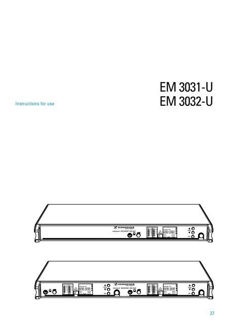
Instructions for use<br />
EM 3031-U<br />
EM 3032-U<br />
27
Thank you for choosing <strong>Sennheiser</strong>!<br />
You have made an excellent choice. This product will give you reliable and cost-effective ease of<br />
operation over many years. All of <strong>Sennheiser</strong>’s professional expertise and more than fifty years of<br />
experience have gone into the creation of this state-of-the-art product.<br />
Please take a few moments to read these instructions carefully. We want you to enjoy your new<br />
receiver quickly and to the full.<br />
Chapter<br />
Contents ............................................................................................................................. Page<br />
1 Brief description, variants, special features ........................................................... 29<br />
2 Connections and operating elements ..................................................................... 30<br />
3 Noise reduction with HiDyn plus ® ................................................................................................................................................. 32<br />
4 Diversity reception .................................................................................................. 33<br />
5 Assembly and mounting, assembly instructions ................................................... 34<br />
6 Connection and mounting of remote antennæ ...................................................... 36<br />
7 Switching the mains voltage / Mains connection .................................................. 37<br />
8 Putting the receiver into operation ......................................................................... 38<br />
9 Changing the receiving frequency ......................................................................... 39<br />
10 Selection and combination of possible receiving frequencies ............................... 40<br />
11 Reprogramming the receiving frequencies – no problem! ................................... 41<br />
12 Display of frequency groups ................................................................................... 41<br />
13 Power of the received radio signal ......................................................................... 32<br />
14 Squelch (Muting), AF squelch ................................................................................ 32<br />
15 Advanced muting function ..................................................................................... 43<br />
16 Monitoring the sound signal, headphone connection .......................................... 44<br />
17 Replacing a fuse ....................................................................................................... 45<br />
18 <strong>Sennheiser</strong> transmitters report their battery status ............................................... 46<br />
19 Suitable <strong>Sennheiser</strong> transmitters ............................................................................ 47<br />
20 Error messages ........................................................................................................ 48<br />
21 Error checklist ......................................................................................................... 48<br />
22 Safety instructions ................................................................................................... 48<br />
23 Recommended accessories ...................................................................................... 49<br />
24 Technical data .......................................................................................................... 50<br />
28
1 Brief description<br />
With the EM 3031-U and EM 3032-U receivers, <strong>Sennheiser</strong> offers the professional <strong>user</strong> high<br />
quality RF receivers with a high level of operational reliability and ease of use. The EM 3031-U<br />
and EM 3032-U receivers together with the suitable hand-held and pocket transmitters permit<br />
wireless transmission with studio quality sound. Due to further optimised PLL and microprocessor<br />
technology and the <strong>Sennheiser</strong> patented HiDyn plus ® noise reduction system, these transmission<br />
systems surpass the signal-to-noise ratio and dynamic range of modern CD productions. The true<br />
diversity technology of the EM 3031-U and EM 3032-U receivers ensures interference-free<br />
transmission and minimises the drop-outs in the RF path.<br />
Especially for small television studios and theatres, the simultaneous use of several EM 3031-U /<br />
EM 3032-U receivers is an economical alternative to technically more sophisticated and therefore<br />
more expensive multi-channel systems.<br />
Variants<br />
EM 3031-U: Single-32-channel true diversitiy receiver<br />
EM 3032-U: Two-32-channel true diversitiy receiver<br />
Note<br />
EM 3031-U and EM 3032-U differ in the fact that the EM 3032-U contains two<br />
complete true diversity receivers in a single 1 U rack housing. These two receivers<br />
are powered by a common mains power supply unit and via a common pair of<br />
antennæ (antenna splitter integrated).<br />
This <strong>manual</strong> is therefore always restricted to the description of just one receiver,<br />
the operation of the second receiver in the EM 3032-U is similar.<br />
<br />
<br />
<br />
<br />
<br />
<br />
<br />
Special features<br />
PLL microprocessor control, programmable<br />
<strong>Sennheiser</strong> HiDyn plus ® noise reduction system<br />
High transmission reliability due to true diversity reception<br />
Ease of use<br />
“LOW BATT“ display for transmitter battery status<br />
19" 1 U housing<br />
Supply voltage for external antenna boosters<br />
29
2 Connections and operating elements<br />
<br />
Headphone socket 1 / 4 “ (6.3 mm) ø<br />
<br />
Headphone volume control<br />
<br />
Multi-function display panel<br />
<br />
Buttons for selecting the receiving frequency<br />
<br />
SET/storage button for channel programming<br />
Changing the receiving frequency:<br />
<br />
<br />
Button <br />
Buttons , or <br />
Button for about 3 seconds<br />
<br />
ON / OFF switch<br />
30
Fuse holder and mains voltage selection<br />
2-pin IEC mains connector<br />
Squelch control<br />
Straw relief clamp for mains cable<br />
Service interface (not used in normal operation)<br />
AF output XLR-3, balanced<br />
Control for AF output level at the XLR socket <br />
Antenna input B<br />
Antenna input A<br />
31
3 Noise reduction with HiDyn plus ®<br />
Progress you can hear:<br />
This receiver is equipped with HiDyn plus ® , the <strong>Sennheiser</strong> noise reduction system. HiDyn plus ®<br />
reduces interference from the RF Line. It increases the signal-to-noise ratio in wireless audio<br />
transmission to up to 110 dB. The dynamic range of a CD is a maximum of 96 dB (16-bit transducer)<br />
and is thus surpassed considerably.<br />
HiDyn plus ® is a wideband compander system which compresses the AF level on the transmitter<br />
side in a ratio of 2:1 (related to dB), and expands it in an exactly the same way on the receiver side.<br />
The optimisation of the dynamic range and the supporting effect of the control amplifier in the<br />
transmitter effectively reduce modulation problems.<br />
HiDyn plus ® has been developed for use in high quality radiomicrophone systems.<br />
Note<br />
Only transmitters which are also equipped with HiDyn plus ® can work perfectly in<br />
combination with the EM 3031/3032 receiver. If this is not the case, the dynamic<br />
range is drastically reduced, the transmission sounds blunt and flat. HiDyn plus ®<br />
can not be switched off on the EM 3031/3032 receiver.<br />
32
eceiver 1<br />
AF-signal<br />
electronic switching<br />
from one signal to another<br />
AF-signal<br />
receiver 2<br />
4 Diversity reception<br />
The EM 3031/3032 receiver operates on the “true diversity” principle:<br />
A receiving antenna receives not only the electromagnetic waves which reach it by a direct path,<br />
but also the reflections of these waves which are created in the room by walls, windows, ceilings<br />
and fittings. When these waves are superimposed, destructive interference occurs, which can also<br />
be called “field strength gaps”. Repositioning the receiving antenna can bring a solution, provided<br />
the transmitter remains in its original position. With mobile transmitters, however (which all<br />
radiomicrophones are ), the “field strength gap“ will then occur with a different transmitter position.<br />
These “field strength gaps“ can only be eliminated with true diversity receivers.<br />
In true diversity, instead of one antenna and one receiver there are now two antennæ and two<br />
receiver sections. The antennæ are spatially separated. By means of a comparison circuit, the<br />
receiver section with the strongest RF signal is always switched to the common AF output. The<br />
risk of the occurrence of “field strength gaps” in both antennæ at the same time is virtually<br />
nonexistant.<br />
The display panel of the receiver always shows whether the diversity channel switched is channel<br />
A or channel B.<br />
33
5 Assembly and mounting<br />
Use as a stand-alone receiver<br />
For use as a stand-alone receiver, it is recommended that the supplied telescopic antennæ are used.<br />
They can be mounted quickly and easily to the rear of the receiver and are suitable for all applications<br />
where – good reception conditions provided – a wireless transmission system is to be used without<br />
a large amount of installation work.<br />
To ensure that the receiver is securely mounted<br />
on a surface on which it can not slip, four selfadhesive<br />
soft rubber feet are supplied. These feet<br />
are stuck into the recesses on the lower side of<br />
the receiver.<br />
Ensure that the recesses are clean and free from<br />
grease before mounting the feet.<br />
N.B.<br />
Do not use these feet if rack-mounting<br />
the receiver.<br />
34
Mounting the receiver into a rack<br />
With the two rack mount “ears“ supplied, the receiver can be mounted into a 19" rack (1 U). The<br />
rack mount “ears“ are screwed to the receiver on the left and right .<br />
Note<br />
If you wish to connect the antennæ to the front side, you must now pull the cables<br />
of the GA 3030-AM antenna mount through the holes on the rack mount “ears“<br />
before mouting the “ears“ .<br />
The GA 3030-AM antenna mount (accessory, see chapter 23) allows the antennæ to be connected<br />
to the front of the receiver, for example if the rear of the rack is closed.<br />
Mount the antenna holders to the right and left to the handles of the receiver . The connection<br />
cables, which are firmly fixed to the antenna holders, are connected to the antenna sockets on the<br />
rear of the receiver.<br />
Assembly instructions<br />
<br />
<br />
Do not place receivers in direct proximity to digitally controlled devices!<br />
Site the receivers as high as possible so that the receiving antennæ have a<br />
“free line of sight” to the transmitter antennæ!<br />
35
6 Connection and mounting of remote antennæ<br />
If the receiver position is not the best antenna position for optimum reception, you can use remote<br />
antennæ. These are available as accessories.<br />
The best reception quality is obtained with the <strong>Sennheiser</strong> A12 AD-UHF active antenna. Antenna<br />
and receiver can be connected with a RG 58 co-axial cable. Ready made up antenna cables from<br />
<strong>Sennheiser</strong> are available as accessories with lengths of 1 m, 5 m and 10 m (see chapter 20)<br />
Attention!<br />
To supply the antenna booster integrated in the A12 AD-UHF active antenna, a<br />
direct voltage (which can not be switched off) is output via the antenna sockets. If<br />
you use antennæ from other manufacturers instead of the A12 AD-UHF, take into<br />
account that these must be installed with direct voltage decoupling, i.e. isolated.<br />
The output voltage supply is short circuit-proof, but an active antenna connected<br />
to this supply increases the power consumption of the overall device.<br />
Notes on mounting the antennæ (which absolutely must be adhered to)<br />
<br />
<br />
<br />
Position antennæ in the same room in which the transmission takes place!<br />
Maintain a minimum distance of 1 metre from metal objects (including walls of<br />
reinforced concrete)!<br />
Maintain a minimum distance of 1 metre between the receiving antennæ!<br />
36
7 Switching the mains voltage<br />
Before you plug the mains connector into the mains, please check first of all<br />
that the receiver is set to the correct mains voltage!<br />
You can switch the mains voltage by removing the fuse holder with the inserted fuse , turning<br />
it through 180° and inserting it again , . The rated voltage set can now be seen at the top of<br />
the fuse holder.<br />
Mains connection<br />
Insert the mains cable supplied into the socket on the receiver and pass the cable through the<br />
traction relief .<br />
Because of the traction relief, the cable can no longer slip out of socket and interrupt operation.<br />
Note<br />
A straw relief clamp is particularly important when the receiver is permanently<br />
rack mounted. Inside the rack there are often a large number of cables - a straw<br />
relief clamp bracket prevents the cables from pressing each other out.<br />
37
8 Putting the receiver into operation<br />
The receiver is switched on with the ON / OFF switch . Display panel is now lit up to show<br />
that the receiver is switched on, and the last frequency set is shown (see chapter 10). The display<br />
“MUTE“ (see chapter 13) is lit up . If a suitable transmitter is already operating on this frequency,<br />
the display “MUTE“ is initially lit up for about 4 seconds. Then the display changes to “RF“ and<br />
“DEV“ (RF level and modulation, see chapter 13), and the diversity branch in use is displayed<br />
(see chapter 4).<br />
Note<br />
The ON / OFF switch works in the secondary circuit of the integrated mains<br />
transformer, and thus only switches the low voltage side. By using a modern magnetic<br />
core transformer, the power consumption of a EM 3031/3032 receiver of approx.<br />
1<br />
/ 2 Watt when switched off is extremely low. For larger installations with several<br />
receivers, a complete mains disconnection can best be achieved by an additional<br />
common ON / OFF switch.<br />
The AF connection is via the socket on the rear. The control controls the AF signal<br />
output level.<br />
38
9 Changing the receiving frequency<br />
To change the receiving frequency, please proceed with the following steps:<br />
<br />
<br />
Press button (“SET“). The text “FREQUENCY MHZ” in display panel begins to flash.<br />
With buttons (/) you can now select a different frequency. The display always jumps<br />
to the next fixed frequency setting in the program. 8 channels are allocated to each range.<br />
The 4 possible ranges are always shown by the display in display panel .<br />
Have you set the frequency correctly? Then press button (“SET“) again for about 3<br />
seconds. Your entry is confirmed by the fact that the text “FREQUENCY MHZ” ceases to flash. At<br />
the same time, “SŠł“ appears and the other displays in display panel go off briefly.<br />
Only now does the receiver change to the new frequency, any existing RF link to a<br />
transmitter on the previous frequency is interrupted.<br />
You can discontinue your entry at any time by briefly pressing button (“SET“). The cancellation<br />
is briefly confirmed on the display panel with “ESC“. The receiver switches back to normal<br />
operation and the text “FREQUENCY MHZ” ceases to flash. The frequency to which the receiver was set<br />
appears again.<br />
After about 5 seconds, the receiver then automatically returns to normal operation if no entry has<br />
been made during this period. Here, too, “ESC“ flashes briefly. You must then begin operation over<br />
again.<br />
39
10 Selection and combination of possible receiving frequencies<br />
Each EM 3031 receiver (or each of the two EM 3032 receivers) can be programmed with a<br />
maximum of 32 receiving frequencies within the switching bandwidth. These receiving frequencies<br />
are divided into 4 groups.<br />
Each group can contain from 0 to 8 receiving frequencies.<br />
Pre-programming and group assignment is carried out by<br />
the factory according to your specifications.<br />
Possible specifications for frequency combinations:<br />
<br />
Use of several receivers to make up a multi-channel system<br />
With this frequency combination, the receiving frequencies are divided into groups such<br />
that they can simultaneously be used within one group (or several groups) without causing<br />
intermodulation interferences.<br />
1 ... 8 1 ... 16 ... ...<br />
<br />
Use of receivers in different places<br />
Here, a frequency group is assigned to a TV channel. If one or several receiving frequencies<br />
are subject to interference (e.g. due to TV transmitters), please choose a frequency group<br />
in a different TV channel.<br />
40
Number of receiving frequencies<br />
For ease of use, or if required by country-specific restrictions on the frequency usage, it is<br />
also possible to program less than 32 receiving frequencies.<br />
Your local <strong>Sennheiser</strong> distributor will be happy to help you<br />
in the selection of your receiving frequencies.<br />
11 Reprogramming the receiving frequencies – no problem!<br />
If you wish – for whatever reason – to change your receiving frequencies, reprogramming, within<br />
the limits of the receiver’s specifications, can be carried out without any problems by your local<br />
<strong>Sennheiser</strong> service department.<br />
12 Display of frequency groups<br />
In the selection of receiving frequencies, the receiver goes through the four groups in succession.<br />
The groups are shown on the display panel in display . Each additional illuminated dot represents<br />
a further group:<br />
1 2 3 4<br />
41
13 Power of the received RF signal<br />
In display panel , the power of the received RF signal in (µV) and the level control of the AF<br />
signal – i.e. the modulation of the RF signal (in %) are shown. Both displays have an<br />
overmodulation display. If the signal is too high, the text “PEAK“ lights up briefly. Short<br />
overmodulation is not critical. Where longer overmodulation occurs, the modulation of the<br />
corresponding transmitter must be reduced. For the AF signal, “peak hold” is also shown, which<br />
means that short peaks remain visible for some time.<br />
14 Squelch (Muting)<br />
The EM 3031/3032 receiver is equipped with an adjustable squelch control which eliminates<br />
annoying noise when the transmitters are switched on and off. It also suppresses sudden noise<br />
when a transmitter leaves the reception area and there is no longer sufficient transmitter power<br />
received by the receiver.<br />
The squelch is adjusted on the rear of the receiver with control (“MUTING“). The adjustment<br />
range is between 0 and about 100 µV. When the squelch is active, the text “MUTE“ is shown in<br />
display panel .<br />
AF squelch<br />
The squelch also switches on when the selected radio channel is occupied by a wideband interference<br />
signal such as that generated by lighting control systems. This prevents an interfering signal from<br />
hindering reception even when the interfering signal has a high RF level. When control <br />
(“MUTING“) is set to position “0“, the AF squelch is also switched off.<br />
42
AMF<br />
AMF<br />
15 Advanced muting function<br />
This receiver also features AMF (Advanced Muting Function). This special electronic feature<br />
comes into effect when an RF signal drops by about 50 dB in a short time. The reception is then<br />
muted for 3 seconds. AMF thus suppresses the annoying switch-off click when a transmitter is<br />
switched off. Because of the delay in switching on again, the PLL circuit of the transmitter has<br />
enough time to adjust itself back to the corresponding transmission frequency.<br />
Example<br />
One possible area of use for AMF is the inaudible change of a hand-held transmitter.<br />
If the battery of the first transmitter has run down (display “LOW BATT“ on the<br />
receiver), a second transmitter is prepared on the same frequency: insert battery,<br />
select transmission channel. Then the first transmitter is switched off, AMF switches<br />
to mute and the second transmitter is immediately switched on. The PLL of<br />
transmitter 2 stabilises itself, AMF switches on again. The whole procedure takes<br />
place inaudibly in the background while AMF is switched to mute. Without AMF,<br />
the switching off, switching on and stabilising of the transmission frequency would<br />
have been audible in the form of possible crackles and whistling noises.<br />
AMF can be switched off. As it is coupled with the setting of the normal squelch, its function is<br />
cancelled if control (“MUTING“) is turned to position “0”.<br />
43
16 Monitoring the sound signal, headphone connection<br />
Socket on the EM 3031/3032 receiver can be used to monitor the sound signal received with<br />
headphones. The headphone volume is adjusted with control .<br />
Please use headphones with a 1 / 4 “ (6.3 mm) ø stereo jack plug. The sound signal itself is mono.<br />
The <strong>Sennheiser</strong> HD 25 headphone is especially usefull for this purpose.<br />
In order to judge the quality of the received sound signal even under unfavourable conditions (low<br />
AF level in the transmitter) and with high ambient noise (e.g. on the stage), the sound signal at<br />
socket can be monitored at an amplification of up to 30 dB compared with the LINE output.<br />
For strong sound signals, however, this can distort the sound if control is turned to a high level.<br />
In this case, turn control down until the distortion disappears. If the distortion remains, the<br />
transmitter itself is overmodulated.<br />
Volume up? – No!<br />
First of all, the volume control should always be adjusted to the lowest volume<br />
(by turning it anti-clockwise as far as possible). Then turn up the volume control <br />
gradually until you have reached the desired volume.<br />
When people use headphones, they tend to choose a higher volume than with<br />
loudspeakers. Listening at high volume levels for long periods can lead to permanent<br />
hearing defects. Please protect your hearing, and as far as possible, check the sound<br />
signal only briefly with the headphone.<br />
44
17 Replacing a fuse<br />
Disconnect the receiver completely from the mains! To do so, pull out the mains connector on<br />
the receiver. You can then remove the fuse holder with the inserted fuse. Replace the fuse by a<br />
new fuse with the same rating and switch on the receiver again. Make sure that you have inserted<br />
the fuse holder in such a way that the receiver is operated with the correct mains power!<br />
A faulty fuse should always be regarded as a warning. In most cases, the cause is harmless – a<br />
short voltage surge or some similar cause has triggered the protective mechanism. When the fuse<br />
has been replaced, the receiver works again.<br />
If the replacement fuse also blows, please consult a specialist who can discover the cause. We<br />
recommend you to contact your <strong>Sennheiser</strong> distributor or to send the receiver, with a precise<br />
description of the trouble, to a <strong>Sennheiser</strong> service departement in your area. You can find the<br />
address of your nearest service departement in the enclosed Service card or on the Internet under<br />
“http://www.sennheiser.com”.<br />
45
18 <strong>Sennheiser</strong> transmitters report their battery status<br />
<strong>Sennheiser</strong> supplies hand-held and pocket transmitters which provide information on the available<br />
transmitter battery status to the receiver. This information can be evaluated with the EM 3031 /<br />
EM 3032 receivers.<br />
When the battery capacity is so low that only a transmission time of about 20 to 30 minutes<br />
remains, the text “LOW BATT“ flashes on the display panel .<br />
You should now immediately replace the transmitter battery. The AMF (Advanced Muting Function)<br />
in the EM 3031 / EM 3032 receiver helps you, as far as possible, to maintain the transmission<br />
without noise (see chapter 15).<br />
<br />
<br />
Notes<br />
The “LOW BATT“ display is reset by the mute function. Whenever the squelch is<br />
activated in the receiver, the “LOW BATT“ display goes off and the evaluation of the<br />
feedback from the transmitter starts over again.<br />
Under favourable reception conditions, the evaluation of the battery information<br />
from the transmitter lasts about 10 – 20 seconds. However, it can be significantly<br />
longer if reception is subject to interference from time to time. This time is then<br />
also needed by the display in display panel in order to update the information<br />
shown.<br />
46
19 Suitable <strong>Sennheiser</strong> transmitters<br />
For the optimum use of the excellent reception qualities of the EM 3031 / EM 3032 receivers,<br />
<strong>Sennheiser</strong> offers hand-held and pocket transmitters in a variety of configurations:<br />
Pocket transmitters: SK 1063-U (without display of battery condition)<br />
BF 1083-U (without display of battery condition)<br />
SK 50-U<br />
(with display of battery condition)<br />
SK 250-U (with display of battery condition)<br />
Hand-held transmitters: SKM 1072-U (without display of battery condition)<br />
SKM 3072-U (with display of battery condition)*<br />
SKM 5000-U (with display of battery condition)<br />
Information on the many possible combinations of <strong>Sennheiser</strong> products and their use in multichannel<br />
systems can be found in the planning brochure “Practical Applications in RF Technology”<br />
which your <strong>Sennheiser</strong> distributor has in stock or will be pleased to order for you from <strong>Sennheiser</strong>.<br />
Up to date information on <strong>Sennheiser</strong> products can also be found<br />
on the Internet under “http://www.sennheiser.com”.<br />
<strong>Sennheiser</strong> products are exclusively distributed through authorised <strong>Sennheiser</strong> distributors. We<br />
regret that deliveries direct to private customers are not possible.<br />
* available from approx. 4/97<br />
47
20 Error messages<br />
The display panel of the receiver is also used by the integrated microprocessor to display error<br />
messages for service purposes. If you see error messages such as ERR ¡, ERR , ERR £ or ERR ¢, there<br />
is a fault in the receiver unit which can only be corrected by your local <strong>Sennheiser</strong> service departement.<br />
21 Error checklist<br />
Error<br />
Possible cause<br />
Receiver does not work;<br />
operating display dark Fuse defective<br />
Receiver does not work;<br />
operating display lit up Frequency of transmitter does not agree<br />
with receiving frequency<br />
• Switching threshold adjustment for<br />
mute function too high<br />
Sound distorted AF output signal adjusted too high. Input<br />
of the connected mixing console or<br />
amplifier is overmodulated<br />
<br />
Transmission microphone overmodulated<br />
(see corresponding section in the operating<br />
<strong>manual</strong> of the transmitter)<br />
Sound overlaid with background noise Transmitter not sensitive enough; where<br />
appropriate, switch transmitter sensitivity<br />
from ”low” to ”high”<br />
22 Safety instructions<br />
<br />
<br />
<br />
<br />
<br />
Never open electronic devices! This must only be done by authorised personnel and is all<br />
the more important for current-carrying units. If devices are opened by customers in breach<br />
of this instruction, the warranty becomes null and void.<br />
Always disconnect the unit from the main by removing the plug when you wish to change<br />
connections or move the device to a different place.<br />
Keep the system away from central heating radiators and electric heaters. Never expose it<br />
to direct sunlight.<br />
Use the system in dry rooms only.<br />
Use a damp cloth for cleaning the device. Do not use any cleansing agents or solvents.<br />
48
23 Recommended accessories<br />
• Antenna mount GA 3030-AM Cat. no. 04368<br />
• Active antenna A 12 UHF Cat. no. 04156<br />
• Ground plane antenna GZA 1036-9 Cat. no. 02332<br />
• Co-axial cable, 1 m GZL 1019 A1 Cat. no. 02324<br />
• Co-axial cable, 5 m GZL 1019 A5 Cat. no. 02325<br />
• Co-axial cable, 10 m GZL 1019 A10 Cat. no. 02326<br />
• BNC coupler GZV 1019A Cat. no. 02368<br />
• Active antenna splitter<br />
acc. to customer specifications AS-X Cat. no. 03273<br />
• Monitoring headphone HD 25 Cat. no. 02976<br />
49
24 Technical data EM 3031 / EM 3032<br />
RF characteristics<br />
Frequency range<br />
430–960 MHz<br />
Receiver frequencies<br />
max. 32 in 4 groups,<br />
pre-programmedto customer specifications<br />
Switching bandwidth<br />
24 MHz<br />
Frequency stability<br />
± 10 ppm (-10°C to +55°C)<br />
Sensitivity (with HiDyn plus ® )<br />
typ: 5 µV for 90 dBAeff SNR<br />
Squelch treshold<br />
0 to 100 µV, adjustable<br />
Image rejection<br />
≥ 50 dB, typ. 65 dB<br />
Adjacent channel rejection<br />
≥ 75 dB<br />
Intermodulation attenuation typ. 66 dB (400 kHz/800 kHz)<br />
Free field interference radiation 30 – 2000 MHz > -57 dBm (2nW)<br />
Antenna input<br />
2 BNC sockets<br />
Antenna input impedance<br />
50 Ω<br />
AF characteristics<br />
Modulation<br />
wideband FM<br />
Compander system <strong>Sennheiser</strong> HiDyn plus ®<br />
De-emphasis 50 µs<br />
Nominal/peak deviation<br />
±40 kHz/± 56 kHz<br />
AF frequency response<br />
45–20,000 Hz<br />
AF outputs LINE 3-pin XLR, transformer balanced<br />
MONITOR<br />
1<br />
/ 4 “ (6.3 mm) ø jack plug<br />
(mono signal on stereo socket<br />
Signal to L- and R-ring, sleeve earthed)<br />
AF output voltage at peak deviation<br />
LINE: 0–5.6 V adjustable, ≥ 2 kΩ<br />
MONITOR: 0–2.8 V adjustable, ≥ 600 Ω<br />
Amplification on monitor output<br />
30 dB<br />
Source impedance of AF output<br />
≤ 50 Ω (LINE at max. level)<br />
Signal-to-noise ratio<br />
120 dBA eff<br />
at 1 mV RF<br />
and peak deviation<br />
116 dB external eff<br />
106 dB CCIR peak<br />
THD at 1 kHz and nominal deviation ≤ 0.5%, typ. 0.25%<br />
Overall device<br />
Temperature range<br />
-10°C to +55°C<br />
Power supply 115/230 V AC +10%/-15%<br />
Power consumption EM 3031 / 3032<br />
max 10 VA / max 15 VA<br />
Dimensions (without rack mount “ears”) 436 x 215 x 43 mm (19", 1 U)<br />
Weight approx EM 3031 / 3032<br />
3300 g / 4000 g<br />
50
Änderungen vorbehalten<br />
Subject to alterations<br />
Sous réserve de modification<br />
Con riserva di modifiche<br />
Reservado el derecho a introducir modificaciones<br />
Wijzigingen voorbehouden<br />
<strong>Sennheiser</strong> electromic GmbH & Co. KG Telefon +49 (0)5130/600 0<br />
D-30900 Wedemark Telefax +49 (0)5130/600 300<br />
Printed in Germany Publ. 02/97 58822 / A02