

Owner's Manual - Smarthome
Owner's Manual - Smarthome
Owner's Manual - Smarthome

Create successful ePaper yourself
Turn your PDF publications into a flip-book with our unique Google optimized e-Paper software.
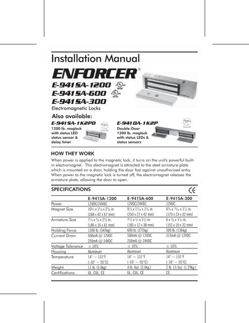
Installation <strong>Manual</strong><br />
ENFORCER®<br />
E-941SA-1200<br />
E-941SA-600<br />
E-941SA-300<br />
Electromagnetic Locks<br />
Also available:<br />
E-941SA-1K2PD<br />
1200 lb. maglock<br />
with status LED<br />
status sensor &<br />
delay timer<br />
Status LED<br />
E-941DA-1K2P<br />
Double-Door<br />
1200 lb. maglock<br />
with status LEDs &<br />
status sensors<br />
Status LED<br />
HOW THEY WORK<br />
When power is applied to the magnetic lock, it turns on the unit's powerful builtin<br />
electromagnet. This electromagnet is attracted to the steel armature plate<br />
which is mounted on a door, holding the door fast against unauthorized entry.<br />
When power to the magnetic lock is turned off, the electromagnet releases the<br />
armature plate, allowing the door to open.<br />
SPECIFICATIONS<br />
Power<br />
Magnet Size<br />
Armature Size<br />
Holding Force<br />
Current Drain<br />
Voltage Tolerance<br />
Housing<br />
Temperature<br />
Weight<br />
Certifications<br />
E-941SA-1200<br />
12VDC/24VDC<br />
10½ x 1 5 /8 x 2 5 /8 in.<br />
(268 x 42 x 67 mm)<br />
7 1 /4 x 5 /8 x 2 3 /8 in.<br />
(185 x 16 x 61 mm)<br />
1200 lb. (545kg)<br />
500mA @ 12VDC<br />
250mA @ 24VDC<br />
± 10%<br />
Aluminum<br />
14° ~ 131°F<br />
(-10° ~ 55°C)<br />
11 lb. (5.0kg)<br />
UL, CUL, CE<br />
E-941SA-600<br />
12VDC/24VDC<br />
9 7 /8 x 1 1 /16 x 1 5 /8 in.<br />
(250 x 27 x 42 mm)<br />
7 1 /4 x 1 /2 x 1 1 /2 in.<br />
(185 x 12 x 38 mm)<br />
600 lb. (272kg)<br />
500mA @ 12VDC<br />
250mA @ 24VDC<br />
± 10%<br />
Aluminum<br />
14° ~ 131°F<br />
(-10° ~ 55°C)<br />
4 lb. 6oz. (2.0kg.)<br />
UL, CUL, CE<br />
E-941SA-300<br />
12VDC<br />
6 3 /4 x 15 /16 x 1 1 /4 in.<br />
(170 x 23 x 32 mm)<br />
6 x 3 /8 x 1 1 /4 in.<br />
(152 x 10 x 32 mm)<br />
300 lb. (136kg)<br />
315mA @ 12VDC<br />
± 10%<br />
Aluminum<br />
14° ~ 131°F<br />
(-10° ~ 55°C)<br />
2 lb. 13.5oz. (1.29kg.)<br />
CE
ELECTROMAGNETIC LOCK Installation <strong>Manual</strong><br />
MOUNTING THE E-941SA-300, E-941SA-600 & E-941SA-1200<br />
A. Drill holes for the mounting plate and<br />
armature plate (see fig. 1 and 2) by<br />
doing the following:<br />
1. Fold the mounting template along<br />
the dotted line.<br />
2. Close the door. Find a mounting<br />
location on the door frame near<br />
the upper free-moving corner of<br />
the door, as close to the corner of<br />
the door frame as possible.<br />
3. Place the template against the<br />
door and frame.<br />
4. Drill two holes in the door frame<br />
and three holes in the door as<br />
indicated on the template.<br />
NOTE — A filler plate or an L-bracket<br />
or Z-bracket (optional) may be<br />
required for the electromagnet,<br />
depending on the door frame. See<br />
fig. 1. Z/L brackets are not available<br />
for E-941SA-300.<br />
B. Mount the armature plate to the door<br />
using at least two steel and one<br />
rubber washer (fig. 2):NOTE — Actual<br />
installation varies according to door<br />
style.<br />
1. Put one rubber washer between<br />
two steel washers, and place them<br />
over the armature screw between<br />
the armature plate and the door.<br />
This will allow the armature plate<br />
to pivot slightly around the<br />
armature screw in order to<br />
compensate for door misalignment.<br />
2. Tighten the sexnut bolt enough so<br />
the armature plate can withstand<br />
the force of someone attempting to<br />
break down the door while the<br />
electromagnet is engaged.<br />
3. Do not tighten the armature plate<br />
against the door. The plate must<br />
be able to pivot around the<br />
armature screw.<br />
Page 2<br />
4. Make sure the anti-spin guides are<br />
in the two guidepin holes.<br />
C. Screw the mounting plate to the door<br />
frame or optional bracket:<br />
1. Screw the two short self-tapping<br />
screws in the slotted holes of the<br />
mounting plate and adjust the<br />
position of the mounting plate so<br />
that it and the armature plate form<br />
a 90-degree angle.<br />
2. Once the position is correct, use<br />
the long self-tapping screws to<br />
permanently mount the bracket.<br />
3. Remove the two short screws.<br />
D. Drill the cable access hole.<br />
E. Mount the electromagnet to the door<br />
frame (fig. 1) — Use the Allen wrench<br />
to screw the socket-head mounting<br />
screws through the bottom of the<br />
electromagnet into the mounting<br />
bracket. (Brass sleeves will be needed<br />
for the E-941SA-600.)<br />
F. Connect the power leads (fig. 3):<br />
1. Open the electromagnet.<br />
2. Run two power leads from the<br />
power supply through the cable<br />
access hole into the<br />
electromagnet.<br />
3. Connect the power leads to the<br />
terminal block.<br />
4. Close the electromagnet.<br />
Note: E-941SA-300 is for 12VDC<br />
operation only. Connect the red wire to<br />
+12VDC, and the black wire to ground.<br />
G. Test the unit.<br />
H. Insert the tamper caps into the<br />
mounting screw access holes. This<br />
should be the last step, as once the<br />
tamper caps are in place, they will be<br />
difficult to remove.<br />
SECO-LARM U.S.A., Inc.
+<br />
-<br />
ELECTROMAGNETIC LOCK Installation <strong>Manual</strong><br />
FIG.<br />
1<br />
For Inswing Doors<br />
Filler<br />
Plate*<br />
Standard<br />
Mounting<br />
* Note: may require more<br />
than one filler plate.<br />
"L" Bracket<br />
(Z/L brackets are not available for E-941SA-300.)<br />
"Z"<br />
Bracket<br />
FIG.<br />
2<br />
Sexnut tube<br />
Sexnut<br />
bolt<br />
12345<br />
12345<br />
Steel and<br />
Rubber washers<br />
(as needed)<br />
Armature<br />
Armature<br />
Screw<br />
Sexnut<br />
bolt<br />
Steel and<br />
Rubber<br />
washers<br />
(as<br />
needed)<br />
12345678<br />
12345<br />
12345678<br />
Armature<br />
12345<br />
Screw<br />
Steel and<br />
Rubber washers<br />
(as needed)<br />
Armature Screw<br />
This side drill<br />
16mm only<br />
Drill a 8mm<br />
hole thru door<br />
HOLLOW METAL DOOR<br />
Drill an 8mm hole thru door. From sexnut<br />
bolt side only, enlarge the 8mm hole to<br />
16mm.<br />
Armature<br />
Drill 12.7mm<br />
(1/2") Drill a 8mm<br />
hole thru door<br />
SOLID CORE DOOR<br />
Drill an 8mm hole thru door. From sexnut<br />
bolt side of door, drill 12.7mm (1/2") hole,<br />
25mm (1") in depth.<br />
Armature<br />
Tap M8 x 1.25 Thread<br />
REINFORCED DOOR<br />
Drill a 6.8mm dia. hole and tap for<br />
M8 x 1.25 thread.<br />
FIG. 3<br />
(E-941SA-600 &<br />
E-941SA-1200 only)<br />
E-941SA-600<br />
Power<br />
Supply<br />
+<br />
-<br />
Power Cable<br />
To Magnet<br />
ENFORCER<br />
Control<br />
Device<br />
+<br />
-<br />
INPUT<br />
POWER<br />
Voltage Selection<br />
12VDC<br />
Magnet set for 12VDC<br />
operation as supplied<br />
from factory.<br />
24VDC<br />
Position a jumper over the<br />
two middle pins for 24VDC<br />
operation.<br />
Voltage Selection<br />
12VDC<br />
Magnet set for 12VDC<br />
operation as supplied<br />
from factory.<br />
24VDC<br />
Position a jumper over the<br />
two middle pins for 24VDC<br />
operation.<br />
Power Cable<br />
To Magnet<br />
INPUT<br />
POWER<br />
+<br />
-<br />
ENFORCER<br />
Control<br />
Device<br />
E-941SA-1200<br />
Power<br />
Supply<br />
Important note:<br />
Check jumper settings before connecting the<br />
lock to the 24VDC input power. Damage to the<br />
lock may result from incorrect jumper settings.<br />
Page 3
®<br />
ELECTROMAGNETIC LOCK Installation <strong>Manual</strong><br />
TROUBLESHOOTING<br />
Problem:<br />
Door does not lock<br />
Door locks, but can be<br />
easily forced open<br />
Delay in door releasing<br />
Possible cause:<br />
No power<br />
Poor contact between<br />
electromagnet and<br />
armature plate<br />
Incorrect voltage<br />
setting<br />
A secondary diode was<br />
installed across the<br />
electromagnet<br />
Solutions:<br />
• Check to make sure the wires are<br />
securely tightened to the terminal block<br />
• Check that the power supply is connected<br />
and operating<br />
• Make sure the lock switch is wired<br />
correctly<br />
• Make sure the electromagnet and<br />
armature plate are properly aligned<br />
• Make sure the contact surfaces of the<br />
electromagnet and armature plate are<br />
clean and free from rust<br />
• Check the power leads with a meter, and<br />
make sure 12VDC or 24VDC is present<br />
• The electromagnet is fitted with a metal<br />
oxide varistor to prevent interference, so<br />
do not install a secondary diode<br />
REGULAR MAINTENANCE<br />
• Clean the contact surfaces of the electromagnet or armature plate with a soft cloth and nonabrasive,<br />
non-corrosive cleaner.<br />
• Apply a light coat of a silicon lubricant to prevent rust. Wipe away the excess.<br />
• Check that the armature plate is securely attached to the door, yet can pivot slightly around the<br />
armature screw.<br />
• Check that the electromagnet is securely attached to the door frame.<br />
UL CERTIFICATION<br />
E-941SA-600 and E-941SA-1200 electromagnetic locks conform to UL/10B “Fire Tests of Door<br />
Assemblies” and UL/10C “Positive Pressure Fire Tests of Door Assemblies” for swinging door<br />
assemblies. They are also classified in accordance with the Uniform Building Code standard 7-2.<br />
WARRANTY: ENFORCER Electromagnetic Locks are warranted against defects in<br />
material and workmanship while used in normal service for a period of one (1) year from the<br />
date of sale to the original customer. Our obligation is limited to the repair or replacement of any<br />
defective part if the unit is returned, transportation pre-paid, to SECO-LARM.<br />
NOTICE<br />
The information and specifications printed in this manual are current at the time of publication.<br />
However, the SECO-LARM policy is one of continual development and improvement. For this reason,<br />
SECO-LARM reserves the right to change specifications without notice. SECO-LARM is also not<br />
responsible for misprints or typographical errors.<br />
Copyright © 2003 SECO-LARM U.S.A., Inc. All rights reserved. This material may not be reproduced<br />
or copied, in whole or in part, without the written permission of SECO-LARM.<br />
SECO-LARM ® U.S.A., Inc.<br />
16842 Millikan Avenue, Irvine, CA 92606<br />
Tel: 800-662-0800 / 949-261-2999 Fax: 949-261-7326<br />
Page 4<br />
Website: www.seco-larm.com<br />
E-mail: sales@seco-larm.com<br />
PITGW1<br />
E-941SAd.pmd<br />
SECO-LARM U.S.A., Inc.
ELECTROMAGNETIC LOCK Installation <strong>Manual</strong><br />
Page 5


