Read Installation Instructions - Chris Alston's Chassisworks
Read Installation Instructions - Chris Alston's Chassisworks
Read Installation Instructions - Chris Alston's Chassisworks

You also want an ePaper? Increase the reach of your titles
YUMPU automatically turns print PDFs into web optimized ePapers that Google loves.
READ ALL INSTRUCTIONS COMPLETELY AND THOROUGHLY UNDERSTAND THEM BEFORE DOING ANYTHING.<br />
CALL VARISHOCK TECH SUPPORT (916) 388-0288 IF YOU NEED ASSISTANCE.<br />
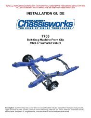
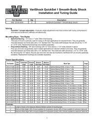
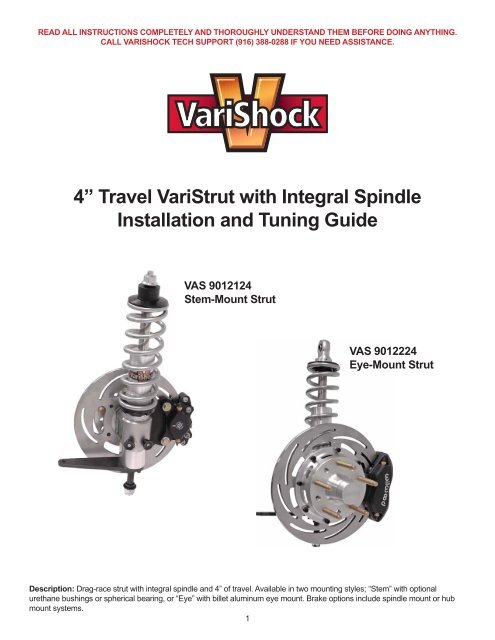
4” Travel VariStrut with Integral Spindle<br />
<strong>Installation</strong> and Tuning Guide<br />
VAS 9012124<br />
Stem-Mount Strut<br />
VAS 9012224<br />
Eye-Mount Strut<br />
Description: Drag-race strut with integral spindle and 4” of travel. Available in two mounting styles; “Stem” with optional<br />
urethane bushings or spherical bearing, or “Eye” with billet aluminum eye mount. Brake options include spindle mount or hub<br />
mount systems.<br />
1
PARTS LIST<br />
EYE-MOUNT STRUT<br />
VAS 9012224 – Eye Mount 4” Travel VariStrut<br />
Part Number Qty Description<br />
899-020-210 1 pr. Eye-mounted VariStrut assembly with integrated spindle, 4” travel<br />
VAS 21-09XXX 1 VariSpring 2-1/2” ID, 9” length (pair)<br />
6191 1 Control-arm set, VariStrut<br />
6192 or 6193 (optional) 1 Rod-end kit for control arms, 6192 7/16” bore, 6193 1/2” bore<br />
899-020-210 – Eye Mount 4” Travel VariStrut<br />
Part Number Qty Description<br />
883G400-CC0G 2 VariStrut 4” travel assembly<br />
VAS 502-100 1 Strut stud base and steering arm set<br />
VAS 506-100 1 Eye mount and spring seat set<br />
VAS 502-100 – Strut Stud Base and Steering Arm<br />
Part Number Qty Description<br />
2019 2 Spindle washer 1-1/2” x 3/4”<br />
3108-038H-S 4 Lock washer 3/8” high-collar<br />
3122-038C1.00B 4 12-point flange bolt 3/8-16 x 1”<br />
3145.156-1.00C 4 Cotter pin 5/32 x 1” long<br />
3630 2 Castle nut 3/4-20 steel<br />
3174-250-0.75S 6 Dowel pin .25 diameter x .75 long<br />
899-052-200 2 Base extension for integral spindle strut<br />
899-052-201 2 Steering arm for integral spindle strut, 3/8-24<br />
899-052-203 2 Strut control arm pivot stud<br />
899-052-204 2 Pivot spacer lower strut pivot<br />
899-057-625-18 2 Castle nut 5/8-18 steel<br />
VAS 506-100 – Eye Mounts and Spring Seats<br />
Part Number Qty Description<br />
3106-19CC0.63B 4 Set screw 10-24 x 5/8” cone point<br />
3106-31CK0.25SP 4 Set screw 5/16-18 x 1/4” cup point<br />
899-002-200 2 Lower spring seat for 2-1/2”-ID coil springs<br />
899-002-202 2 Upper spring seat for 2-1/2”-ID coil springs<br />
899-010-203 2 Top strut eye, COM-8 bearing<br />
899-013-203 2 Piston bump stop 7/8 “ID x 2” OD x 5/8” tall, urethane<br />
899-017-2431-22 4 Detent spring<br />
899-018-250 4 Stainless steel ball .250 diameter<br />
899-029-50-1.00 2 Spherical bearing 1” OD x 1/2” bore, Teflon® lined<br />
899-030-1.000 2 Retaining ring 1 .00” bore, internal<br />
899-053NTA-1625 2 Thrust bearing 1” bore x 1-1/2” OD<br />
899-053TRA-1625 4 Thrust washer 1” bore x 1-1/2” OD<br />
2
PARTS LIST<br />
STEM-MOUNT STRUT<br />
VAS 9012124 – Stem Mount 4” Travel VariStrut<br />
Part Number Qty Description<br />
899-020-209 1 pr. Stem-mounted VariStrut assembly with integrated spindle, 4” travel<br />
VAS 21-09XXX 1 VariSpring 2-1/2” ID, 9” Length (pair)<br />
6191 1 Control-arm set, VariStrut<br />
6192 or 6193 (optional) 1 Rod-end kit for control arms, 6192 7/16” bore, 6193 1/2” bore<br />
VAS 505-100 or<br />
VAS 505-101<br />
1 Chassis mount urethane bushing or spherical bearing<br />
899-020-209 – Stem Mount 4” Travel VariStrut<br />
Part Number Qty Description<br />
883H400-CC0G 2 VariStrut 4” travel assembly<br />
VAS 502-100 1 Strut stud base and steering arm set<br />
VAS 506-101 1 Stem mount and spring seat set<br />
VAS 502-100 – Strut Stud Base and Steering Arm<br />
Part Number Qty Description<br />
2019 2 Spindle washer 1-1/2” x 3/4”<br />
3108-038H-S 4 Lock washer 3/8” high-collar<br />
3122-038C1.00B 4 12-point flange bolt 3/8-16 x 1”<br />
3145.156-1.00C 4 Cotter pin 5/32 x 1” long<br />
3630 2 Castle nut 3/4-20 steel<br />
3174-250-0.75S 6 Dowel pin .25 diameter x .75 long<br />
899-052-200 2 Base extension for integral spindle strut<br />
899-052-201 2 Steering arm for integral spindle strut, 3/8-24<br />
899-052-203 2 Strut control arm pivot stud<br />
899-052-204 2 Pivot spacer lower strut pivot<br />
899-057-625-18 2 Castle nut 5/8-18 steel<br />
VAS 506-101 – Stem Mounts and Spring Seats<br />
Part Number Qty Description<br />
3106-31CK0.25SP 4 Set screw 5/16-18 x 1/4” cup point<br />
3132-063-18B 2 Flanged locknut 5/8-18<br />
899-002-200 2 Lower spring seat for 2-1/2”-ID coil springs<br />
899-002-202 2 Upper spring seat for 2-1/2”-ID coil springs<br />
899-013-203 2 Piston bump stop 7/8 “ID x 2” OD x 5/8” tall, urethane<br />
899-013-68-1.75 4 Top mount bushing .688 bore x 1.75 diameter, urethane<br />
899-017-2431-22 4 Detent spring<br />
899-018-250 4 Stainless steel ball .250 diameter<br />
899-053NTA-1625 2 Thrust bearing 1” bore x 1-1/2” OD<br />
899-053TRA-1625 4 Thrust washer 1” bore x 1-1/2” OD<br />
899-059-201 4 Top bushing mount backup washer, aluminum<br />
3
PARTS LIST<br />
STEM-MOUNT STRUT<br />
CHASSIS MOUNT OPTIONS:<br />
VAS 505-100 – Chassis Mount, Urethane Bushing<br />
Part Number Qty Description<br />
2065 4 Chassis mount gusset 1/8” thick, 4130<br />
2066 2 Chassis mounting plate 1/8” thick, 4130<br />
VAS 505-101 – Chassis Mount, Spherical Bearing<br />
Part Number Qty Description<br />
1166 2 Spherical-bearing housing<br />
1268 2 Safety nut 5/8-18<br />
1328 2 Thrust stand .340” offset, billet aluminum<br />
2064 2 Chassis mounting plate 1/8” thick, 4130<br />
2065 4 Chassis mount gusset 1/8” thick, 4130<br />
3117-063-18C 2 Locknut 5/8-18 half height, nylon insert<br />
3395 2 Spherical bearing 1-3/8” OD x 3/4” bore, Teflon® lined<br />
3679 2 Spirolox retaining ring 1.442 OD<br />
PARTS LIST<br />
EYE- AND STEM-MOUNT STRUT<br />
BRAKE OPTIONS:<br />
Spindle-Mount-Wheel Brake Kit (8364)<br />
Part Number Qty Description<br />
3915 1 Brackets single-piston caliper set<br />
3918 1 Light-duty slotted rotor, 10-1/4” diameter (pair)<br />
3919 1 Hat set for 10-1/4” diameter rotor (pair)<br />
3988 1 Billet single-piston Dynalite caliper & pads (pair)<br />
Light-Duty Brake Kit (8365)<br />
Part Number Qty Description<br />
3905 or 3906 1 10” rotor set, 3905 solid, 3906 slotted (pair)<br />
3914 1 Light-duty billet hubs & bearings (pair)<br />
3916 1 Brackets two-piston caliper set<br />
3996 1 Billet two-piston Dynalite calipers & pads (pair)<br />
Medium-Duty Brake Kit (8366)<br />
Part Number Qty Description<br />
3903 or 3904 1 11-3/4” rotor set, 3903 solid, 3904 slotted (pair)<br />
3910 1 Medium-duty billet hubs & bearings (pair)<br />
3917 1 Brackets four-piston caliper set<br />
3989 or 3990 1 Forged four-piston Dynalite calipers & pads, 3989 black, 3990 polished (pair)<br />
4
INSTRUCTIONS<br />
I. CHASSIS MOUNT INSTALLATION<br />
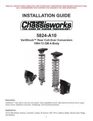
Note: To maintain proper front end geometry, the enclosed drawing (899-031-202-A) shows the location of all suspension<br />
mounting points in reference to the ground line. The view of the drawing is from the front of the chassis. The ride height of the<br />
strut is shown with a 12” rolling radius tire. If you have a larger or smaller tire, adjust the dimensions to match your tires installed<br />
rolling radius.<br />
A. Installing Upper Strut Mounts on Chassis Forward Struts<br />
1. Before you can install the upper strut mounts, you must determine what strut mount width you need for your<br />
tires to clear your fenders. Due to the many different front wheel and tire combinations, you should do the following<br />
calculations for your vehicle even if it is listed in the chart on your chassis instructions.<br />
Step 1: Determining the outside front tire width. Measure the width between the front fenders. You will need 4 to 5<br />
inches of clearance from the outside sidewall of the tire to the inner front fender lip. If you choose 4” of clearance,<br />
subtract 8” from the inner fender width. If you need 5” of clearance, subtract 10” from the inner fender width. This<br />
will equal the outside front tire width.<br />
Step 2: To determine the hub width, you need to know how much wider the outside of the tire is than the front hub.<br />
Put a yardstick across the outside sidewall of the tire and measure through the center to the side of the wheel that<br />
bolts to the hub. This is the amount that the wheel, when bolted on, is wider than the hub. Multiply this amount by 2<br />
and then subtract that amount from the outside tire width you calculated in step one. This will be the required hub<br />
width (A) on the drawing.<br />
Step 3: Subtract 11-1/2” from the hub width obtained in Step 2 to find the top strut mount width. Write your top<br />
mount width (B) on the drawing.<br />
2. The front spindle centerline will be used to locate all the strut mounting points. Using your chassis assembly drawing,<br />
mark the axle centerline on the driver and passenger front frame rails.<br />
3. Install the forward struts using the upper strut mount to position them.<br />
Stud Mount: Measured from the chassis centerline, install the stud mount strut with the bottom of the cup or<br />
plate 21-1/2” above the ground line, 10 degrees angle toward the rear of the chassis, or 1-7/8” behind the spindle<br />
centerline and 1/2 the “B” dimension calculated above. The cup also tilts out at the bottom as viewed from the front.<br />
Stem Mount: Measured from the chassis centerline, install the eye mount strut with the center of the mounting<br />
brackets 22-1/2” above the ground line, 10 degrees angle toward the rear of the chassis, or 1-7/8” behind the<br />
spindle centerline and 1/2 the “B” dimension calculated above.<br />
B. Installing Control Arms<br />
1. The drawing shows the location of the control arm pivot points in relation to the spindle centerline and the ground<br />
line. These dimensions do not change with the upper strut mounts. The rod end mounting points for the control arms<br />
are 24-1/2” wide and 6-1/8” off the ground line. The front and rear rod end centers are in the same plane. The control<br />
arm kit (part no. 6191) will have instructions on completing the installation of the control arms.<br />
C. Installing Rack-and-Pinion Mounts<br />
1. Shown on the drawing are the rack-and-pinion bracket mounting positions for the Pinto rack and pinion, our (part<br />
no. 6119) and the billet rack clamp (part no. 6124). These dimensions do not change with the upper strut mounts. The<br />
rack-and-pinion mount is offset from the chassis centerline 1-3/4” to the driver side of the chassis and 6-3/4” above<br />
the ground line. The mounting should be level front to rear and right to left. After the rack is mounted, install the tie rod<br />
tubes (part no. 6194).<br />
2. Checking bump steer is an important part of this installation. Bump steer can only be corrected by shimming the tie<br />
rod ends or the rack-&-pinion. Do not move the control arm mounts. It is best to follow the procedures in the tie rod tube<br />
(Part No. 6194) instructions to check this.<br />
5
II. STRUT ASSEMBLY<br />
A. Assembling Strut Base and Steering Arm<br />
1. You will need to assemble the strut base extension and steering arm. Insert the three dowel pins into the holes on<br />
the bottom of the strut.<br />
2. Slide the base extension block over the three dowel pins. Use a rubber hammer to set the base extension tight<br />
against the strut base. Be sure to start the block over all three dowel pins evenly, keeping the extension block and the<br />
strut base perfectly square until the extension base in fully seated.<br />
3. Set the steering arm on the extension block. Slide the 3/8” lockwasher over the 3/8-16x1” 12-point bolts and put a<br />
drop of 277 Red Loctite on each screw. Insert the bolts through the steering arm and into the extension block. To<br />
begin, screw the bolts half of the way into the extension blocks. Make sure you assemble the steering arms to make a<br />
right and left side.<br />
4. Put three drops of 277 Red Loctite on the threads of the control arm pivot stud. Be sure you do this on the end<br />
that does not have the cotter pin cross hole in it. Slide the pivot stud though the steering arm and base extension and<br />
thread it into the base of the strut.<br />
5. Tighten the two 12-point bolts to 30 lb-ft., of torque. Tighten the pivot stud to 80 lb-ft., of torque. Repeat this for the<br />
second strut. Remember to align the steering arms so they are both forward when the strut assemblies are installed<br />
creating a right and left side.<br />
B. Assembling Strut Top Mount<br />
1. Stem Mount Struts require an upper mount plate with an 11/16” hole in it. This plate must be installed in the chassis<br />
so it is exactly perpendicular to the strut at ride height. Failure to meet this requirement will damage the strut. Look at<br />
the assembly drawing to determine the location of each component in the upper mount. DO NOT forget to grease the<br />
thrust bearing. Tighten the top nut to 50 lb-ft., (it is self-locking).<br />
2. Eye Mount Struts require two 1/2” hole brackets per side of the chassis. They must be 1-1/8” apart inside. The pivot<br />
in the upper eye must be perpendicular to the strut at ride height. Failure to meet this requirement will damage the strut.<br />
Eye mounts are easier to build and attach to the chassis than stem mounts. Also, they have more misalignment than<br />
stem mounts. Look at the assembly drawing to determine the location of each component in the upper mount. The<br />
thrust bearing needs to be greased.<br />
The final/correct spring rate must be calculated after installing the baseline-rate spring which was shipped with your<br />
strut. The eye mount may have to be removed after initial installation to change to a different rate spring. Refer to your<br />
VariSpring <strong>Installation</strong> and Tuning Guide for specific instructions on calculating the correct spring rate.<br />
Eye Mount Initial Assembly<br />
Thread the lower spring seat onto the strut body until it is at the bottom of the available threads. Fully extend the strut<br />
piston rod. Place the spring over the piston rod followed by the bump stop, upper spring seat, and thrust bearing. Hold<br />
the piston rod in an aluminum vise jaw and tighten the top eye to 20-25 lb-ft. Do not scratch the piston rod. Follow the<br />
procedures for measuring the spring and calculating the correct spring rate as described in the VariSpring <strong>Installation</strong><br />
and Tuning Guide. If the calculated spring rate differs from the installed spring, the eye mount will have to be removed<br />
to install the correct rate spring.<br />
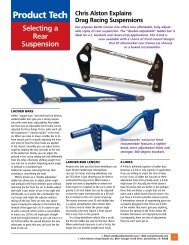
Eye Mount Final Assembly<br />
Grease the thrust bearing during when reassembling the strut with the correct rate spring. Hold the piston rod in an<br />
aluminum vise jaw and tighten the top eye to 45-50 lb-ft. Do not scratch the piston rod. Use a #21 bit (.159”) to drill<br />
shallow (1/16” deep) set screw landings through each of the eye-mount’s 10-24 set screw holes. The landings prevent<br />
the set screws from distorting the piston threads when tightened. Clear the holes of debris before applying #242 Blue<br />
Loctite onto the set screws and installing them into the eye.<br />
NOTE: Removal of the eye mount after final assembly may require heating the mount to break the Loctite bond.<br />
3. After the strut is installed on the chassis, check for binding at full compression and extension and, at full lock of the<br />
steering in each direction. This must be done without the spring installed. You must correct any binding that occurs in<br />
any part of the front suspension or damage will result.<br />
6
C. Installing Coil Spring<br />
1. Apply anti-seize to the threads on the inside of the lower spring seat and then screw the spring seat onto the shock<br />
body. The spanner wrench notches in the lower spring seat go toward the base of the strut (the end opposite where<br />
the shaft comes out). As you screw the lower spring seat on, you will be able to feel the ball locks in the spring seat<br />
snapping into the reservoir grooves. If you have trouble screwing the seat on, make sure that the set screws that secure<br />
the ball lock are not too tight. Unscrew the set screws so one thread shows. Screw the seat on as far as it will go.<br />
2. Place the spring over the strut. In most cases, you will have to compress the spring a little to slide the top seat<br />
between the spring and top eye. Remember, the 1-3/4” diameter counter bore in the upper spring seat goes against the<br />
top eye. The 2-1/2” diameter ledge goes into the spring.<br />
3. Make sure both lower spring seats are screwed on the same amount or you will preload the chassis. With the correct<br />
spring rate, the spring seat will normally be approximately 1” up from the bottom of the adjustment. Check the ride<br />
height using the upper strut mount location off the ground line.<br />
4. After the strut is final installed and adjusted, tighten the set screws to lock the lower spring seat in place. Never adjust<br />
the lower coil spring seat without first jacking up the car to remove the vehicle weight from the spring. Also, make sure the<br />
threads on the reservoir body are clean of any dirt before adjusting the spring seat.<br />
III. INSTALLING THE BRAKES<br />
Refer to the installation guide included with your brake kit for specific instructions.<br />
Spindle Mount Brakes (Part No. 8364) are for light vehicles and must always be used with a parachute. These brakes provide<br />
very little braking and are designed to be extremely light. ONLY FOR USE WITH Weld Racing Wheels - Alumastar 2.0 (788-<br />
15001) and Magnum Pro (786-15001 or 786P-15001) and American Racing Wheels - Torq Thrust® Pro (48553S) and TrakStar<br />
(48053SBC or 48053S).<br />
Light Duty Brakes (Part No. 8365) are also for use on light cars. They provide a braking power similar to that of the spindle<br />
mount brakes. It is a little heavier because it is designed for a bolt-on wheel. It will have a little better rotor and pad life than the<br />
spindle mount brake. It also must be used with a parachute.<br />
Medium Duty Brakes (Part No. 8366) provide much more stopping power and are recommended by <strong>Chassisworks</strong> for use<br />
whenever possible. This kit will provide better pad and rotor life. A parachute is recommended but many lightweight cars have<br />
had good pad and rotor life without one. It is your responsibility to determine the safest way to operate your vehicle.<br />
7
VariStrut Adjustment and Tuning Guide - QuickSet 2<br />
This guide covers adjustment features and tuning procedures for VariStrut QuickSet 2, double-adjustable strut. The information<br />
contained has been greatly simplified and is only intended to get you started in the right direction. Suspension tuning involves<br />
multiple variables such as: spring rates, antiroll bar rates, vehicle weight distribution, tire sizes, tire pressures, suspension<br />
geometry, and track conditions. We highly recommend thoroughly researching suspension tuning and vehicle dynamics, or<br />
consulting an experienced professional.<br />
Travel Limiters<br />
Struts are not to be used as travel limiters. An extension travel limiter, such as a strap or cable, should be used to prevent<br />
topping out and damaging the struts. The installed compression bumper protects the strut if bottomed out during normal use.<br />
If the bumper shows signs of wear or damage it must be replaced immediately. Never operate a vehicle with a missing or<br />
damaged bumper. Vehicles that consistently land harshly from wheel stands should use a higher rate spring along with some<br />
form of suspension stop to limit compression travel without directly impacting the strut body. Any strut will be damaged if the car<br />
is dropped from a wheel stand.<br />
Ride Height<br />
When a strut is at ride height a certain amount of travel is available in either direction. Drag race vehicles generally require more<br />
extension (rebound) travel to help weight transfer, and because the drag strip is very flat, less compression travel is needed.<br />
The amount of extension travel available in the strut will drastically affect how the car works. The VariStrut drag race strut has<br />
4” of travel. At baseline ride height, the strut and spring should collapse 2.56” from their installed heights. This results in 2.56” of<br />
available extension travel and 1.44” of compression travel.<br />
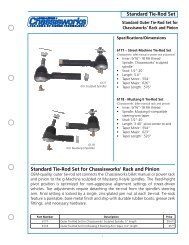
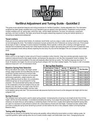
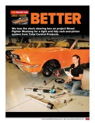
Baseline Spring Rate Selection<br />
9” Spring Rate Baseline<br />
Spring rate affects ride quality, ride height, stored Front Vehicle Rate Spring<br />
energy, weight transfer and how effectively the front Weight (lbs) (lb/in) Travel (in)<br />
suspension handles downward movement after<br />
the launch. Differences in vehicles such as specific<br />
performance application, weight reduction and<br />
chassis stiffening should be taken into consideration.<br />
Additional springs can be purchased for tuning<br />
purposes. The recommended spring rates are based<br />
on the combination of front end weight of the car and<br />
baseline strut ride height. Put scales under the front<br />
tires to determine the actual weight, and then refer<br />
to the baseline spring rate chart. The recommended<br />
rate assumes that the strut travel is at the designed ride height with the strut collapsed 2.56”.<br />
Spring Preload<br />
The threaded lower spring seat is used to adjust spring preload. Compressing the coil spring to any length shorter than it’s free<br />
height, with the strut fully extended, is considered preloading the spring. If you adjust the spring seat to change the vehicle’s<br />
ground clearance, be aware that you will be adding or subtracting travel in the front strut. Usually when lighter-than-baseline<br />
spring rates are used it is necessary to add preload to achieve the correct balance of travel and ride height. If preload has been<br />
added make sure there is adequate spring travel remaining to prevent coil bind before the strut is fully collapsed. (Refer to the<br />
Spring Rate Baseline chart.)<br />
Tuning with Spring Rate<br />
A drag race car should run the lightest front spring rate possible, without letting the struts bottom out when making a pass. As<br />
a general guideline, lighter springs allow the car to easily transfer weight, and settle faster down track. Changing spring rate<br />
affects ride height and the rate at which weight is transferred to the rear tires. A softer rate makes the front easier to raise during<br />
acceleration. A stiffer rate makes the front harder to raise during acceleration. If you are having trouble getting the front end to<br />
rise, you can soften strut rebound valving or change to a softer spring. When using lighter rate springs preload must be added<br />
by screwing the lower spring seat upward, compressing the spring to achieve proper ride height. In general terms, the worse<br />
a car hooks the more strut extension travel it will need. If you need more extension travel, preload can be removed to lower<br />
ride height. Using this method will cause the car to have less ground clearance and reduce the amount of compression travel.<br />
If you are going to operate the strut at a ride height shorter than recommended, the upper chassis mounts must be relocated<br />
to correct any major vehicle ride height issues. It may take some work with spring rates and upper mount relocation to get the<br />
correct combination of vehicle ride height and front suspension travel for your application.<br />
8<br />
Maximum<br />
Preload (in)<br />
Part Number<br />
900-975 185 5.70 1.58 VAS 21-09185<br />
975-1125 210 5.64 1.52 VAS 21-09210<br />
1125-1275 240 5.57 1.45 VAS 21-09240<br />
1275-1475 275 5.46 1.34 VAS 21-09275<br />
1475-1650 310 5.57 1.45 VAS 21-09310<br />
1650-1800 350 5.17 1.05 VAS 21-09350
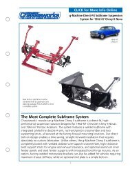
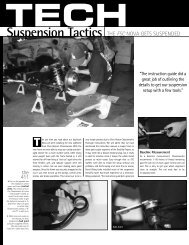
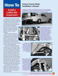
Adjustment Features<br />
The QuickSet 2 valve system features dual adjustment knobs that<br />
independently control bump- and rebound-damping stiffness of the<br />
strut. Dual-arrow symbols engraved into the strut body demonstrate<br />
the function of each knob. Arrows pointing toward each other<br />
designate bump (compression) adjustment; the strut collapsing.<br />
Arrows pointing away from each other represent rebound (extension)<br />
adjustment; the strut extending. Knobs are clearly etched indicating<br />
the correct direction of rotation to decrease (-), or increase (+)<br />
damping stiffness. There are 16 specific adjustment positions for<br />
each knob, with a total of 256 unique combinations possible.<br />
<br />
<br />
<br />
<br />
Position 1, the softest setting, is found by turning the knob in<br />
the counter-clockwise direction until the positive stop is located.<br />
Rotating the knob in the clockwise direction increases damping<br />
stiffness. Each of the 16 settings is indicated by a detent that can be<br />
felt when turning the knob, and an audible click as the knob gently<br />
locks into position. Only very light force is necessary to rotate the<br />
knob past each detent. If access to the adjustment knobs is limited,<br />
a 5/64 ball-drive Allen wrench can be used to adjust the knob. Do<br />
not force the knob beyond its intended stop, doing so will damage<br />
the valve mechanism.<br />
Symbol Direction Effect<br />
+ Clockwise Increase Stiffness<br />
- Counter-Clockwise Decrease Stiffness<br />
<br />
<br />
Bump (compression) Adjustment<br />
<br />
<br />
Rebound (extension) Adjustment<br />
Note: VariStruts have a substantial range of adjustment with very little bypass or internal bleed. Due to our minimal-bleed<br />
design, struts will feel extremely stiff at some settings when operated by hand, whereas other struts with excessive bleed<br />
will move more freely. Manual comparison should not be performed. A person cannot manually operate the strut at a rate<br />
anywhere near real life conditions and any results found in this manner will be meaningless. Prior to shipping, every VariStrut is<br />
dynamometer (dyno) tested and calibrated throughout an accurate range of shaft speeds and cylinder pressures found in realworld<br />
operation.<br />
The Truth About 16- vs. 24-Clicks<br />
Don’t be fooled by struts offering more adjustment clicks. They are actually 1/2-click adjustments. The manufacturer merely<br />
added more detents to the mechanism without increasing the range of adjustment. This practice gives more clicks, but the<br />
adjustment is so slight that your vehicle will not respond to the change. A 16-position VariStrut actually has a broader range of<br />
adjustable force with the added benefit of a more manageable number of adjustments to try.<br />
Tuning Procedures - QuickSet 2<br />
VariStrut’s broad range of adjustment is suitable for the unique vehicle dynamic requirements of drag racing. A properly tuned<br />
drag race suspension effectively controls weight transfer and maintains traction throughout launch and each gear shift. Before<br />
proceeding verify that all suspension components, such as control arms, balljoints, and bushings are in acceptable condition<br />
and that tire pressures are correctly set.<br />
Tuning for Drag Racing - QuickSet 2<br />
Required settings for drag racing applications vary greatly depending upon, vehicle weight, weight distribution, suspension<br />
geometry and travel, horsepower, and available traction. A properly tuned drag race suspension enables the vehicle to<br />
launch straight while transferring weight to the rear tires in an efficient, controlled manner. Extensive testing and adjustment is<br />
critically important when operating your vehicle at or near its performance limits. Testing must be done in a safe and controlled<br />
environment, such as a dedicated motorsports facility. It is generally better to tune struts and shocks according to improvements<br />
in ET’s (Elapsed Times) rather than for specific occurrences such as the amount of wheel-stand. Due to differences in weight<br />
distribution, wheel base, tire size, and horsepower, not all vehicles leave the starting line in the same manner once their<br />
suspension has been optimized. Watch your ET’s and if your times start to get slower return to the prior adjustment. Once you<br />
have completed the following procedures, only fine adjustments may be needed to tune for specific track conditions.<br />
Prior to Testing<br />
Make certain that wheelie bars are raised as high as possible while maintaining control and eliminating their influence as much<br />
as possible on damper settings. Begin with struts adjusted to the number 3 position for bump and rebound.<br />
9
Initial Testing<br />
First verify that the vehicle tracks straight before aggressively launching from the line. Begin with light acceleration and low<br />
speeds. If the vehicle tracks and drives acceptably at this level, make incremental increases in acceleration and top speed<br />
until the vehicle is safe at higher speed. Vehicles not tracking straight at speed should verify all chassis settings including but<br />
not limited to alignment, bump steer, tire pressures, etc. Once the vehicle drives in a safe manner at speed, move on to test<br />
launching.<br />
Test launches should consist of only the initial launch with no subsequent gear changes. Begin with low rpm launches and<br />
gradually increase rpm and severity if the car launches acceptably. At this time we are only determining that the car launches in<br />
a controlled manner to avoid damaging components or the vehicle. The vehicle should leave in a straight line without extreme<br />
wheel standing or harsh bounces. Sudden, uncontrollable front end lift should be corrected by making suspension instant center<br />
adjustments, if possible. More gradual front end lift can be corrected by adjusting the strut valving. If the car gradually wheel<br />
stands or bounces violently, adjust front suspension first, then rear. If there is rear tire shake, wheel hop or excessive body<br />
separation, adjust rear suspension first, then front. If your car is launching severely to the right or left, first check that the rear<br />
end is centered and there is no preload adjusted into the rear suspension. If the car still launches severely to the right or left,<br />
you will have to add preload to the rear suspension. If everything checks out okay and the car only minimally drives to the right<br />
or left, you can stagger the rear shock valving to correct this.<br />
Use of a double-adjustable QuickSet 2 will allow the following procedure.<br />
When a vehicle launches slightly toward the right, rebound (shock extension) stiffness is added to the driver side and bump<br />
(shock compression) stiffness is added to the passenger side. A vehicle launching slightly toward the left would make the<br />
opposite adjustments. It is not recommended to have more than two clicks difference side to side for either bump or rebound.<br />
Rear shock adjustments are only applicable to correcting the launch and will have little to no effect on down track performance.<br />
After the car has been adjusted to launch straight, test launch and include the first gear change. Make any required adjustments<br />
and add the next gear change. Repeat until the car can be launched straight and driven at speed safely. The car is now ready<br />
for fine tuning to optimum results.<br />
Front Strut Adjustment<br />
Pay close attention to what is happening to the front end during launch. Your goal is to eliminate all jerking or bouncing movements<br />
during launch and gear shifts. Ideally the front end should rise in a controlled manner, just enough to keep the rear tires loaded,<br />
then continue the pass with smooth transitions at all times. Front end rise without any appreciable traction gain is wasted energy<br />
that should be used to propel the vehicle forward instead of up. While testing, document your ET’s along with any changes made.<br />
If ET does not improve, return to previous settings.<br />
Front Rebound (Extension) Adjustment Overview<br />
Too light of a rebound (extension) setting allows excessive front end chassis separation and may result in the front wheels<br />
jerking violently off the ground during launch. Also, during gear change, too light a setting allows the car to bounce off its front<br />
rebound travel limiter and then bottom out in an oscillating manner. Too firm a setting will prevent the front end from rising<br />
sufficiently, limiting the amount of weight transferred to the rear tires. Adjust the rebound setting in one click increments to<br />
control the rate at which the front end rises at launch and during gear changes. While testing, document your ET’s along with any<br />
changes made. If ET does not improve, return to previous settings.<br />
Front Wheels Lose<br />
Contact with Ground<br />
Rear Tires Hook Then<br />
Lose Traction<br />
No Front End Rise<br />
Increase<br />
Rebound<br />
Stiffness<br />
Increase<br />
Rebound<br />
Stiffness<br />
Decrease<br />
Rebound<br />
Stiffness<br />
Violent chassis separation and may result in jerking the front wheels off the ground.<br />
Increase strut rebound stiffness by one, then test again.<br />
If weight transfer occurs too quickly the rear tires may hook then lose traction as the<br />
front end begins to travel downward. Slowing the rate at which the front end rises<br />
prevents the struts from topping out too quickly and increases the duration of time<br />
that the rear tires benefit from the weight transfer. Increase strut rebound stiffness by<br />
one, then test again.<br />
Too firm of a damper setting limits the amount of weight transferred to the rear tires,<br />
resulting in poor traction. Decrease strut rebound stiffness by one, then test again.<br />
10
Front Bump (Compression) Adjustment Overview<br />
After the launch or during a gear change, a firm bump setting will cause the chassis to bounce off the front tire as the chassis<br />
settles down. Too light of a bump setting allows the strut to bottom out and bounce off the stop travel bumper. Adjust bump in one<br />
click increments to control the amount and rate at which the front end settles during gear change. While testing, document your<br />
ET’s along with any changes made. If ET does not improve, return to previous settings.<br />
Front<br />
“Bottoms<br />
Out“ After<br />
Launch<br />
Hard Front<br />
End Bounce<br />
(After Launch or<br />
Gear Change)<br />
Increase<br />
Bump<br />
Stiffness<br />
Decrease<br />
Bump<br />
Stiffness<br />
If front suspension settles too fast after launch or gear change it may cause the front<br />
suspension to bottom out at the end of its downward travel. If the suspension bottoms out<br />
hard enough, rear traction may be lost. Increase strut bump stiffness by one, then test again.<br />
If increasing bump stiffness cannot extend weight transfer duration long enough, a higher rate<br />
spring should be installed.<br />
If the tires cause the front end to bounce upon landing, the struts are too stiff. The front end<br />
should settle in a single, smooth motion. Decrease strut bump stiffness by one, then test again.<br />
This can be a very subtle problem. Watch the front tire sidewall as it contacts the ground.<br />
Rear Shock Adjustment (Double Adjustable)<br />
Maintain traction by controlling the rate at which torque and weight is transferred to the rear tires. Ideally the rear suspension<br />
should be as firm as possible before a loss of traction occurs. Changes to the vehicle such as ride height, tire size, weight<br />
distribution, or suspension link adjustments will alter the instant center location in relation to the vehicle’s center of gravity. Any<br />
shift of either the instant center or center of gravity will usually require a shock setting adjustment to optimize traction. While<br />
testing, document your ET’s along with any changes made. If ET does not improve, return to previous settings.<br />
Rear End<br />
Squats<br />
Vehicle<br />
Separates<br />
from Rear<br />
End<br />
Loss of<br />
Traction<br />
with Minimal<br />
Chassis<br />
Movement<br />
Increase<br />
Bump<br />
Stiffness<br />
Increase<br />
Rebound<br />
Stiffness<br />
Decrease<br />
Bump/<br />
Rebound<br />
Stiffness<br />
Some vehicles will squat during launches instead of pushing the vehicle forward. To assist<br />
in planting the tires, increase shock bump stiffness by one, then test again.<br />
Some suspension geometries plant the tires so forcefully that the rear end of the vehicle<br />
rises away from the housing too rapidly. The vehicle may hook initially, then spin the tires<br />
once the shocks are topped out. Slowing the rate at which the rear end rises increases<br />
the duration of time that the rear tires benefit from the improved traction. Increase shock<br />
rebound stiffness by one, then test again.<br />
A suspension system that is too stiff can hit the tires too hard, causing a loss of traction.<br />
Softening the suspension slows the transfer of weight and reduces the initial tire shock. Minimal<br />
chassis movement makes if very difficult to visually tell if the bump or rebound needs to be<br />
decreased. We suggest adjusting bump first and watch for a gain or loss in the ET. If ET does<br />
not improve, return to previous setting, then adjust rebound instead and test again.<br />
Completion of Testing<br />
When all adjustments have been completed, reset your wheelie bars as low as possible without affecting your ET.<br />
11
NOTE: Drill two shallow set<br />
screw landings onto piston<br />
threads, using a #21 bit (.159”).<br />
Refer to section II-B-2.
WARRANTY NOTICE:<br />
There are NO WARRANTIES, either expressed or implied. Neither the seller nor manufacturer will be liable for any loss, damage or injury,<br />
direct or indirect, arising from the use or inability to determine the appropriate use of any products. Before any attempt at installation,<br />
all drawings and/or instruction sheets should be completely reviewed to determine the suitability of the product for its intended use. In<br />
this connection, the user assumes all responsibility and risk. We reserve the right to change specification without notice. Further, <strong>Chris</strong><br />
Alston’s <strong>Chassisworks</strong>, Inc., makes NO GUARANTEE in reference to any specific class legality of any component. ALL PRODUCTS ARE<br />
INTENDED FOR RACING AND OFF-ROAD USE AND MAY NOT BE LEGALLY USED ON THE HIGHWAY. The products offered for sale<br />
are true race-car components and, in all cases, require some fabrication skill. NO PRODUCT OR SERVICE IS DESIGNED OR INTENDED<br />
TO PREVENT INJURY OR DEATH.<br />
<strong>Chris</strong> Alston’s <strong>Chassisworks</strong><br />
8661 Younger Creek Drive<br />
Sacramento, CA 95828<br />
Phone: 916-388-0288<br />
Technical Support: tech@cachassisworks.com<br />
899-031-202 REV 12/11/12<br />
16