Complete (13 MB) - Chris Alston's Chassisworks
Complete (13 MB) - Chris Alston's Chassisworks
Complete (13 MB) - Chris Alston's Chassisworks

You also want an ePaper? Increase the reach of your titles
YUMPU automatically turns print PDFs into web optimized ePapers that Google loves.
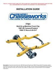
READ ALL INSTRUCTIONS COMPLETELY AND THOROUGHLY UNDERSTAND THEM BEFORE DOING ANYTHING.CALL CHASSISWORKS TECH SUPPORT (916) 388-0288 IF YOU NEED ASSISTANCE.INSTALLATION GUIDE7703Bolt-On g-Machine Front Clip1970-77 Camaro/FirebirdDescription: A-arm front clip bolt-on for 1970-77 Camaro/Firebird. Includes welded front frame clip, body mounts,upper and lower A-arms, spindles, coil-over shock and springs,billet rack and pinion, billet rack and pinion mounts,ties rod ends, disc brake kit, engine mounts, and transmission mount installation instructions.
336INSTALLATION GUIDE70-77 CAMAROS & FIREBIRDS2036Equipment List andHardware ListInstalling Lower & UpperA-arms and Spindles20 Installing Steering Rack26 Front Suspension Alignment33 Installing Antiroll Bar3939 Installing Shocks and Springs4358 5343 Installing Brakes53Installing Engine Mounts andMid Plate58 Installing Manual Transmission72786161 Removing Stock Front Clip72 Installing Bolt-On Frame78Installing TransmissionCrossmember79 Aligning The Frame81Reinstalling FactoryComponents88949684 Installing Steering Shaft88 Installing Fender Flaps94 Installing Headers96Installing SubframeConnectors917703 Page 1
CONGRATULATIONSYou have purchased the finest bolt-on Camaro front frame available. We hope youare as excited about installing it as we were about designing it.This assembly booklet should guide you through a seamless installation. However,if you have any questions please give our tech line a call at (916) 388-0288.Monday through Friday 7:00 a.m. to 5:00 p.m., Saturday 8:00 a.m. to 1:00 p.m. PST.Every effort has been made to insure that each component has been boxedcorrectly. However, we urge you to open each box and verify its contents againstthe enclosed parts list.We also suggest that you read this entire assembly booklet before you begin. Thiswill help you become familiar with the project.Please remember that when you modify a vehicle, you assume all risks. You arechanging the structural integrity manufactured into the original vehicle. As such,you need to be cognizant of potential failures. Initially you must conduct a series ofshort tests in a safe location. Test for handling, steering, and braking at slightlyincreasing speeds.Once you are confident the vehicle handles and stops properly, take a series ofdrives with slightly increasing speeds stopping to check all components. Graduallyincrease the distance of your drives. Once you have confirmed your installation isroad-worthy, you must develop a maintenance program. You must check allcomponents for looseness, and wear and tear on a regular schedule. Yourschedule must be more intense and frequent than a regular OEM vehicle.<strong>Chris</strong> <strong>Alston's</strong> <strong>Chassisworks</strong> would appreciate any feedback regarding yourexperience during installation and use of this frame. If there are any accessories oroptions you would like to see us manufacture, please let our sales departmentknow.That said, let’s install!Page 2 917703
Recommended Equipment ListThis list will give you a good idea of the necessary tools required to complete this installation.There will be additional items needed.Hand Tools Adjustable wrench Allen wrench set Anti-seize compound Brake line wrench Center punch Clecos & pliers 1/8 size Combination wrenches 3/8 to 3/4” Vise grip pliers Drill bit size 1/8 (.125) Level Loctite #242 thread lock Philips screwdriver sizes #1 & #2 Pry bar Wire brush Socket set 3/8 to 3/4” with 3/8 drive 15/16” socket with 1/2” drive ratchet Steel & plastic head hammers Straight blade screwdriver Pliers Tape measure Tap handle small and medium Tap sizes: 10-32, 3/8-16, 7/16-14, 1/2-<strong>13</strong>,5/8-18 Needle nose pliersShop Equipment Floor jack Jack stands –quantity 4 Digital level 3/8” electric drillTorque Specification ChartDESCRIPTIONTORQUEDESCRIPTIONTORQUEA-arm pivot studs50 lb-ftFrame mounting bolt 5/8-11 x 380 lb-ftAntiroll bar clamp socket head allens3/8-16 x 2 1/2”Antiroll bar link eyebolt button head allen3/8-16 x 3/4”Antiroll bar link eyebolt socket head allen3/8-16 x 2 1/4”20 lb-ft20 lb-ft20 lb-ftMotor mount spudsRack clamp socket head allens1/2-<strong>13</strong> x 2”Rack clamp caps socket head allens5/16-18 x 1”Shock spuds20 lb-ft45 lb-ft15 lb-ft20 lb-ftBalljoints150 lb-ftShock bolts 1/2-20 x 2 1/2”45 lb-ftBalljoint studs105 lb-ftTie rod stud60 lb-ftCaliper socket head allens 3/8-16 x 1 3/8”30 lb-ftWheel studs 1/2-20 x 2 1/4” 12 point40 lb-ftFrame mounting bolt 1/2-<strong>13</strong> x 2 1/2”45 lb-ftWe recommend applying a small amount of Loctite on all fasteners except the balljoint studs, and the tie rod studs.917703 Page 3
DISCLAIMER OF WARRANTYPurchasers recognize and understand that products and services manufactured, provided, and/or sold byCHRIS ALSTON’S CHASSISWORKS, INC., are exposed to many varied conditions due to the manner inwhich they are used. Purchasers assume the responsibility to develop a Maintenance Procedure toidentify and replace worn components before they fail. Your Maintenance Procedure must include everycomponent on the vehicle. CHRIS ALSTON’S CHASSISWORKS, INC., makes no claims or guaranteesthat any product or service is designed or intended to comply with any industry standards or governmentregulations. CHRIS ALSTON’S CHASSISWORKS, INC., makes no claims or guarantees in reference toany acceptance for use of its products or services by any entity or racing association, or that its productscan legally be installed on any vehicle that operates on a public highway.CHRIS ALSTON’S CHASSISWORKS, INC., reserves the right to make changes or improvements indesign, materials or specifications or make product changes without incurring any obligation to replace,change or improve products manufactured prior hereto.There are NO WARRANTIES, either expressed or implied. There is no warranty of merchantability.Neither the seller nor manufacturer will be liable for ANY loss, damage or injury direct or indirect, arisingfrom the use or inability to determine the appropriate use of any product. Buyer will not rely onCHASSISWORKS skill or judgment to select or furnish the proper part or equipment for their application.Buyer expressly affirms that they are relying upon their own skill and judgment to select and purchasesuitable goods.Before any attempt at installation, all drawings and/or instruction sheets must be completely reviewed todetermine the suitability of the product for its intended use and that the buyer has the skills required toinstall and maintain the product. Buyer assumes all responsibility and risk for correct installation. CHRISALSTON’S CHASSISWORKS, INC., accepts no responsibility for failure to read, or understand theinstallation guidelines. All products are intended for racing or off-road use and may not be legal forhighway use. The information contained in this Installation Guide is correct to the best of our know-ledgeand belief, having been compiled from reliable sources. However, CHRIS ALSTON’S CHASSISWORKS,INC., cannot assume responsibility for possible error. BUYER IS RESPONSIBLE FOR DETERMININGTHE SUITABILITY OF ANY AND ALL PRODUCTS PURCHASED FROM CHRIS ALSTON’SCHASSISWORKS, INC.It is expressly understood and agreed between purchasers and <strong>Chris</strong> Alston’s <strong>Chassisworks</strong>, Inc., that aspart of the bargain between CHRIS ALSTON’S CHASSISWORKS, INC., and purchasers, and inconsideration of doing business with each other, all purchasers take, select and purchase said racingparts, equipment any and all inventory, or services from CHRIS ALSTON’S CHASSISWORKS, INC., “as is”and “with all faults” and CHRIS ALSTON’S CHASSISWORKS, INC., shall always provide purchasers with afull and complete opportunity to examine, at purchasers’ leisure and convenience, any racing parts andequipment, any and all inventory, or services when purchasing or contemplating purchasing from CHRISALSTON’S CHASSISWORKS, INC. Use of CHRIS ALSTON’S CHASSISWORKS, INC., productsconstitutes acceptance of this agreement in its entirety.BUYER IS RESPONSIBLE FOR DETERMINING THE SUITABILITY OF ANY AND ALL PRODUCTSPURCHASED FROM CHRIS ALSTON’S CHASSISWORKS, INC. NO PART, COMPONENT,INVENTORY, OR SERVICE MANUFACTURED OR SOLD BY CHRIS ALSTON’S CHASSISWORKS, INC.,IS DESIGNED OR INTENDED TO PREVENT INJURY OR DEATH.Purchasers understand and agree that no officer, director, employee, salesperson, or agent of CHRISALSTON’S CHASSISWORKS, INC., has any authority to make any statement contrary to the terms of thisagreement. CHRIS ALSTON’S CHASSISWORKS, INC., disavows any statement contrary to what isherein above written.Page 4 917703
Frame and Sheet Metal Hardware List#3097 HARDWARE BOX FOR CAMARO/FIREBIRD BOLT-ON FRAMEQTY PART DESCRIPTION WHERE USED8 2052 Shim, Camaro clip body mount 2.5x.63x.10 Between floor and body bushings.2 1248 Alignment pin 67-81 Camaro Aligns front clip.3 3430 Button head allen 5/16-18 x 3/4” Caps clutch pivot holes in frame.6 3454 Cup point set screw 1/2-<strong>13</strong> x 1/2” Caps extra holes in frame horns.917703 Page 5
Installing SuspensionNote: The photos in this installation guide were taken using a1967-69 Camaro. There may be slight differences from yourapplication, but the assembly procedure is identical.In this section you will install all of the front suspension components and align the front-endgeometry. It is easier to do this before the new front clip is installed to the body.If you purchased plain steel A-arms, have them painted or powder coated before you assemblethem. Do not get paint in the balljoint housing thread bore or in the pivot bushing bores. Theballjoint bores are precision machined. Consequently, you cannot install and remove the balljointsmultiple times. The self-locking threads on the balljoint will destroy the balljoint housing if it isremoved and installed several times. Have your A-arms painted before the balljoint is assembledto minimize this potential problem.Do not plate or chrome the A-arms. The plating solution can leak into the tubes and cause themto rust from the inside out. If you drill drain holes in the tubes, the A-arm will crack from the holes.If you want a highly polished look, purchase our stainless A-arms.The mild steel lower A-arms are shipped without their pivot bushings installed to make painting orpowder coating easier. Use an arbor press to install the bushings.Installing Upper & LowerA-arms and SpindlesThe first parts installed will be the upperand lower A-arms. The stainless steellower A-arm comes with all of thebushings installed. You will be installingthe bushings and rod ends in the upperA-arms later.For identification, the driver side A-armassembly is embossed with a “D” on theballjoint housing.The passenger side is embossed with a“P” on the balljoint housing.Page 6 917703
The balljoint rubber boot is installed in theballjoint housing first. Because the boot fitstight in the housing, installing it before theballjoint is easier. Drop the boot into themachined bore in the balljoint housing.Work your way around the boot’s edge,pushing it down into the bore with yourfingers. You can also use a blunt tool to dothis.During the assembly process we are goingto coat all of the threaded assemblies withan anti-seize compound to prevent thethreads from being damaged and aiddisassembly in the future.Put a thin layer of anti-seize on the balljointthreads.917703 Page 7
The balljoint is then screwed into the balljointhousing as far as possible by hand. Makeabsolutely sure that the thread startsstraight. This is a little tricky. The threadson the balljoint are easy to cross thread.Use the balljoint wrench included with yourkit to tighten the balljoint. Tighten it until it isfully seated against the balljoint housing.The force required can be over 150 lb-ft oftorque. Be careful not to scratch the A-arm.Repeat this for the passenger side lower A-arm.One convenient method for holding the A-arm while installing the balljoint is totemporarily install the A-arm on the frame.The upper A-arms will be assembled next.Although they are very similar, they are notidentical. The letter “D” or “P” on theballjoint housing identifies which side of thecar the A-arm installs in.Page 8 917703
Use a 5/8-18 tap to chase the threads in theupper A-arm. Clear any debris left in thethreads.Use the same procedure to assemble theupper A-arm as the lower. First, install theballjoint boot into the balljoint housing.Next, apply a layer of anti-seize to theballjoint threads.917703 Page 9
Thread the balljoint in as far as possible byhand.Finish tightening the balljoint with theballjoint wrench until it is seated tight againstthe balljoint housing. Repeat this for thepassenger side upper A-arm.Install the rod ends into the upper A-arms.To provide an initial alignment baseline, thejam nut should be threaded until there is 1-1/16 inches of thread remaining past the jamnut.Page 10 917703
After the application of another dab of antiseize,the rod ends are threaded into theA-arms, until the jam nuts are snug againstthe arm itself.This step must be done carefully becausethe upper and lower A-arm mounts arethreaded and welded to the frame. Use the5/8-18 tap to chase the threads on the frontand backsides of both upper mounts. Blowany remaining particles out of the hole withan air hose.917703 Page 11
Next, chase the threads in the lower A-armmounts with the 5/8-18 tap and blowout anyremaining particles.Now, apply some anti-seize to the threads ofthe pivot stud. Also put anti-seize inside thebore of the A-arm mounts. Insert one of thelower A-arm pivot studs and then run it in allthe way to its stop, it should go in easy. Usethe same procedure to verify all of the pivotstuds will easily thread into their mountinglocations.REARThe lower A-arm fits tight over the mount.Slide the rear of the A-arm onto the mountand then use a piece of wood between theframe and the A-arm to pry it over themount. A 12” piece of 1x2 works well.Page 12 917703
When installing the lower A-arm pivot studs,be careful not to damage the threads. Tapthe pivot stud into place with your hand.If the hand method does not work, you canuse a plastic-tipped hammer to gently installthe pivot stud. It is best to move the pivotstud a small amount at a time until thethreads make contact.Do not put grease on the pivot bushings theyare self-lubricating.Once the pivot studs are in place, use anAllen T-wrench to tighten them. The pivotstuds should go in easily and should betightened until they are fully seated. This willgive the bushings the proper amount ofcrush, and allow the lower A-arm to movewith a small amount of resistance.917703 Page <strong>13</strong>
If you have to remove the lower A-arm pivotstuds, use a piece of wood and a few tapswith a hammer while turning the pivot studcounter-clockwise. The pivot stud will comeout easily.After tightening the lower A-arm pivot studs,check to be sure the A-arm swings freely butsnugly throughout its travel.The lower A-arm should also staysuspended when released. It should take afew pounds of pressure to make it move.Page 14 917703
A set screw is used to lock the A-arm pivotstuds. The set screw locks on the groovemachined into the pivot stud.Before installing the pivot stud set screws,apply a drop of Loctite thread sealingcompound to the screws. Be careful not toget excess Loctite in the pivot stud bore.The next step is to install the upper A-armand spindle. During this step you are goingto need the lower A-arm at its ride heightposition.Two of these shock simulators are includedin the suspension kit. The top holerepresents full shock extension, the bottomhole full compression, and the middle hole(at 12 inches) represents the ride height ofthe shock absorber.917703 Page 15
Next, install the shock simulator at the rideheight position. Install the lower bolt firstand then the upper.Installing the upper A-arm is similar toinstalling the lower A-arm. Slide the frontrod end over the front mount first and thenswivel the rear one into place.Install the upper mount bolts just like thelower mount bolts. Do not fully tighten thembecause they need to be moved when weadjust the front suspension settings later.Repeat the installation of the upper A-armon the passenger side.Page 16 917703
You are now going to install the droppedspindles. The "L" cast into the back of thespindles, does not designate "Left," it is thefoundry mark. The best way to identify thedriver and passenger side spindle is toremember the steering arm (shown witharrow) always goes toward the front of thecar.Place the driver side spindle over theballjoint and thread the 9/16-18 castle nuton.The balljoint castle nut will not thread oneasily if the threads are nicked. A thread filecan be used to correct the problem. Afterfiling, try the castle nut again before puttingthe spindle on. Thread files can be found atmost auto parts stores.917703 Page 17
With the cotter pin installed, use pliers to foldthe legs over the castle nut. One leg goesdown the other over the top of the balljointstud.Repeat the procedure for the upper A-arm.First tightening the castle nut.Install the cotter pin and fold the legs over aswe did on the lower one. Repeat thisprocedure on the passenger side of the car.917703 Page 19
The first step in aligning the new A-arm frontsuspension is to center the rack in its travel.Placing a U-joint on the rack makes turning iteasy.Turn the rack toward the passenger side ofthe car until it stops (full lock position).On the driver side, measure and record thedistance from the rack mount to the end ofthe tie rod end. In our example the length is9 7/8 inches.917703 Page 23
Install the tie rod end in the steering arm.Hold it in place next to the tie rod and adjustthe jam nut until it is against the tie rod end.Remove the tie rod end from the steeringarm and thread it onto the tie rod until itcontacts the jam nut. Next, reinstall the tierod end into the steering arm. Verify thedistance from the frame to the inside of thetie rod end; this should be 8 5/8 inches asmeasured earlier.Repeat this procedure for the passengerside. The measurements are the same asthe driver side.917703 Page 25
Loosely install the castle nut on the tie rodend. Make sure the spindle moves smoothlyfrom full shock extension to fullcompression, as indicated by the holes inthe shock simulator.Now, set the shock simulator in the rideheight position before you start to check thesuspension settings. Do this on the driverand passenger sides.Front SuspensionAlignmentBefore checking the front-end alignment,check to be sure the frame is still level. Puta level on the frame as shown, and adjustthe jack stands until the car is level front torear.Readout from a digital level is preferred foraccuracy when setting the front-endalignment. Level the crossmember and ifneeded, adjust the height by placing shimsunder one of the jack stands.Page 26 917703
First, check and record the camber andcaster readings, they will be adjusted later.The caliper-mounting bosses aremachined perpendicular to the spindle sothey are an excellent place for the level.To check the camber, hold the levelagainst the machined caliper mountingpads on the spindle. Record the reading.Next, check the caster by installing the3/8-16 x 1 3/8” caliper mounting sockethead allens (supplied in your brake kit) intothe threaded bosses on the spindle.Set the digital level against the calipermounting bolts. Record the casterreading. Positive caster is when thespindle top is tipped toward the rear of thecar when viewed from the side.We will now fine tune the camber andcaster settings.917703 Page 27
The adjustment for both caster andcamber is made through theadjustable rod ends on the upperA-arms. Moving both rod ends outincreases positive camber.To adjust caster, move the forwardrod end out further than the rear.This increases positive caster.Adjust the upper A-arm rod ends untilyou have the camber set at zero, or90 degrees on the digital level andthe caster set at 1 to 5 degreespositive. Both sides must be thesame. Remember, if your car has aforward rake when sitting on theground the positive caster will bedecreased by the angle of the bodiesrake. Three degrees of positivecaster with the body level will only be1 degree of positive caster with a 2degree body rake. Adjust one rodend at a time one-half turn until youhave the correct setting. Repeat forthe passenger side before going tothe next step.The next step is setting the toe-in.Cut two pieces of 3/4 inch tubing orelectrical conduit, 26 inches long.Drill a 3/8-inch hole through eachtube 9 inches from one end. Thesetubes will assist in setting the toe-in.Bolt the tube to the upper calipermountingboss with the long end tothe front of the car. The 26-inchlength simulates the tire diameter anddrilling the hole 9 inches from the endcenters the bar over the spindle.Page 28 917703
Next, set the bar level and tighten itdown. Do this on both the driver andpassenger sides.Using two tape measures, measurethe outside width at the front and therear of the tubes. The front dimensionshould be 1/8 to 3/16 less than therear; this is the total amount of toe-in.Record the front and rear dimensionsand calculate the amount of toe-in bysubtracting the front measurementfrom the rear.To adjust the toe-in, rotate the tie rodends to move the spindle in or out asrequired. Make sure to rotate boththe driver and passenger side thesame amount. One-half revolution ofboth tie rod ends will change the toeinby approximately ¼ inch, front toback.917703 Page 29
If rotating the tie rod end 360 degreeschanges the toe-in too much, use therack tie rod to make smaller adjustments.Put the tie rod end in thesteering arm and snug the castle nutbefore adjusting. Use vise-grips tograb onto the tie rod and rotate it toadjust the length. Be careful to turnboth tie rods the same amount.When turning the tie rods, the rubberboot will “wind up" on the tie rod.Once the toe-in is adjusted, use pliersto “unwind” the boot around the tierod. Gently grab onto the outer bootclamp and twist it back around untilthe boots are straight. The jam nutscan now be tightened against the tierod ends.Verify caster, camber and toe-in arecorrect before proceeding.Once the camber, caster, and toe-inare set, tighten down the A-arm boltsand jam nuts, and install the setscrews with a drop of Loctite.Page 30 917703
Next, you can final assemble the tierod ends. Start by installing thegrease zerk fitting in the hole at thebottom.Install the rubber boot.Put the tie rod ends back into thesteering arm. Tighten the castle nutand, install and bend the cotter pinlike you did on the balljoints.917703 Page 31
Grease the tie rod end with a smallgrease gun. Add only enough greaseuntil a small amount starts to comeout from under the rubber boot.Grease the upper and lowerballjoints. Install the zerk fittings andinject grease with a grease gun. Putonly enough grease in to make theballjoint rubber boot bulge out on theside. If you are installing the balljointcaps, remove the zerk fitting.Set the stainless steel cap over theballjoint.Page 32 917703
The caps are held in place with thecountersunk stainless steel allenscrews provided. They screw into thehole where the grease zerk was justremoved. Be sure to remove allgrease from the threads in theballjoint and Loctite thecountersunk allen head screw inplace.Use the same procedure to install thelower balljoint caps.Installing Antiroll BarNext, install the antiroll bar.These are the components of theantiroll bar kit.917703 Page 33
To prevent the urethane bushingsfrom squeaking in action, use thesupplied silicone grease to coat allsides of the urethane bushing thatcontact a metal surface. A thinscrewdriver can be used to smear itaround inside the bushing. Takeextra care not to get this grease allover, it’s very sticky.To open up the bushings, use thehandle end of the balljoint wrenchthat is included in the suspension kit.Once the slot in the bushing isopened, slide it over the antiroll barnear the 90-degree bend.Page 34 917703
With both bushings on the bar, bring it upfrom under the car and set it in position.Center the bushings on the mounting padswelded to your frame.Center the antiroll bar in the frame bymeasuring from the side of the frame to theend of the bar on the driver and passengersides.917703 Page 35
Slide the billet aluminum cap over thebushing and secure with the 3/8-16 x 2 1/2”socket head allen and locknuts provided.Put the urethane bushings into the upperantiroll-bar-link eyebolt.Coat the bushings with the silicone grease.Page 36 917703
Next, slide the link eyebolt onto the end ofthe antiroll bar.Shown here is the hardware used to attachthe link eyebolt to the antiroll bar.Attach the link eyebolt to the antiroll bar.Place the internal tooth lock washer next tothe head of the 3/8-16 x 3/4” button headallen and the beveled stainless steelwasher. Apply Loctite to the button headallen and tighten.Put the star lock washer, bushing washerand one urethane bushing on the 3/8-16 x 21/4 socket head allen. This attaches the linkeyebolt to the lower A-arm. Apply siliconegrease to the bushing on all surfaces.917703 Page 37
Insert the lower bushing assembly into thelower A-arm mount bracket.Grease the upper bushing and slide it andthe other bushing washer over the bolt.Apply Loctite to the bolt. Push down onthe antiroll bar and thread the bolt into theend of the link eyebolt.Page 38 917703
Screw the spring seat adjuster onto theshock. The set screw locking ball allows thespring seat height to be adjusted in ½ turnincrements and then locked once thedesired spring height is set.This upper spring seat holds the spring inplace at the top of the shock. The slotallows the spring seat to be inserted afterthe spring is in place.Slide the rubber bumper down the shockshaft before installing the spring.After dropping the spring over the shock,slide the upper spring seat over the shaft.Page 40 917703
Next, turn the shock over and tighten thespring seat against the spring. After thespring seat makes contact with the spring,turn it one-half of a revolution. This will adda small amount of preload to the coil spring.Tighten the set screw locking ball with anallen wrench. With the spring seat at thisposition, adjusting the spring seat up ordown 1/2-inch can make small changes inthe vehicle ride height.The designed ride height of the suspensionhas the compressed coilover at 12” eye toeye. If you install a 195/65-15 tire on a 6”wide 15” diameter 3 1/2” backspace wheel,the tire will have 6 1/2” of thread width be 8”wide at the section, have a mounteddiameter of 25” and a rolling radius of 12”.This will hold the bottom of thecrossmember 4 1/2” off the ground. The tirewill hold the spindle centerline 12” off theground. If you use a larger or smallerdiameter tire, the crossmember clearancewill change accordinglyThese are the stainless steel shockmounting spuds used at the top and bottomof the shocks. If you did not purchasethese, use the 1/2 x 2-1/2 bolts and locknutsprovided with your suspension kit.Insert the shock from the bottom. It will fitbetween the antiroll bar and the lower A-armshock mount cross tube.917703 Page 41
Install the lower shock spud first. Insert themale shock spud from the front of the carinto the lower A-arm. Insert the female partof the spud from the back, it acts as the nut.Use Loctite to secure threads.Using the spindle shaft as a handle, line upthe top eye of the shock in the upper mountand slide the male spud in. Insert thefemale part of the spud from the back, it actsas the nut. Use Loctite to secure threads.With both halves in place, use two Allenwrenches to tighten the spud together.Tighten them until they stop, the correctamount of crush is calculated into theirlength.Page 42 917703
Installing BrakesThe 11 3/4 inch vented rotors aredirectional. The “P” machined on the insideidentifies the passenger side rotor. There isa "D" on the driver side rotor.These brakes require at least a 15” diameterwheel; however, even some 15” wheels maynot clear. Verify you have at least 1/4” ofwheel clearance from all brake components.The billet aluminum hubs have threadedstud-mounting holes for both 4 1/2 and 4 3/4inch bolt circles.Choose the bolt circle that matches yourwheels and chase the threads with a 1/2-20tap.After chasing the threads, it is a good idea toblow them out with an air hose making sureno debris remains in the holes.Set the rotor over the backside of the billethub. The larger bearing race snout on thehub is the backside. Line up the bolt circleson the hub and the rotor.917703 Page 43
Add a drop of Loctite to the threads, upnear the shoulder and insert the studsthrough the proper series of holes. Theprovided 12-point bolts are 2 1/4 incheslong. If you need a longer wheel stud forthicker wheels, 3-inch long studs areavailable from <strong>Chassisworks</strong>.Tighten the studs from the backside of theassembly. You're ready to install the innerwheel bearing and seal.The bearing races are pressed in the billethub from the factory. You must pack thewheel bearing before installing it. In thephoto, a wheel-bearing packer is shown. Ifyou do not have one available, hand packingthe bearing is okay. If you are unsure howto pack the bearing, refer to an auto repairmanual for assistance.Page 44 917703
After the bearing is packed, drop it in thebearing race. The inner wheel bearing sealis then positioned on the hub.Place the hub on a wood surface beforeinstalling the seal. Using a hammer andseal installer, drive the seal into the hubmaking sure it's fully seated.With the inner bearing and seal in place,slide the hub and rotor assembly onto thecorrect spindle (remember, the rotors aredirectional).917703 Page 45
Pack the outer wheel bearing as you did theinner one. Slide the bearing into the race.Slide the washer over the spindle shaft andinstall the castle nut.To fully seat the bearings, tighten the castlenut to 12 lb-ft while turning the rotorassembly forward by hand. This will removeany grease that could cause excessivewheel bearing play. Back off the castle nutto the "just loose" position and then handtighten. There will be .001 to .005 inches ofend play when the wheel bearings areproperly adjusted.Page 46 917703
After the wheel bearings are tight, insert thecotter pin through the castle nut and the holein the end of the spindle shaft. Do nottighten the castle nut when aligning thecotter pin; only loosen it.Use the same procedure you used on theballjoints to fold the cotter pin legs.Apply anti-seize to the threads of the screwondust cap. Screw the dust cap onto thehub. It only needs to be hand tightened, theo-ring inside will keep it from coming loose.917703 Page 47
Next, install the Wilwood brake calipers.Start by inserting the brake pads into thecaliper, one on each side of the rotor slotwith the metal backing toward the pistons.Slide the caliper with the pads installed overthe rotor and the caliper mounting pads onthe spindle. Use the 3/8-16 x 1 3/8 sockethead allens, lock washers, and flat washersprovided in your brake kit to mount thecalipers. The lock washer goes against thehead of the fastener.Use the T-handle Allen wrench to tighten themounting bolts. Rotate the rotor assemblyslowly to check for any clearance problemsbetween the rotor and the caliper.Page 48 917703
Finally, bolt your wheel and tire on the huband check again to be sure there is at least1/4” clearance between the caliper and thewheel. There are differences in wheelmanufacturer’s tolerances. Make sure yourwheel turns freely. Do not use positiveoffset wheels with this suspension system.Next, remove the plastic plug protecting theinlet port of the Wilwood caliper to start theinstallation of the stainless steel brake lines.Coat the 1/8-pipe threads of the 90-degreebrake line adapter fitting with Loctite teflonsealing compound.Thread the fitting into the caliper. Be sure tostart it straight so you do not cross thread it.If the threads in the caliper get damaged youwill have to replace the caliper.917703 Page 49
Use a 3/8” wrench to tighten the brake lineadapter fitting. The hose end of the fittingshould point toward the lower calipermountingbolt when tight.Remember, the caliper is aluminum and thefitting is steel. Do not over tighten and stripthe threads in the caliper.Thread the swivel end of the stainless steelbrake line onto the adapter fitting until it isfinger tight.Drill and tap the side of the frame for two 10-32 threaded holes. These holes will positionthe brake line tab 2” below the top of theframe and 2-1/2” ahead of the weld at thedropped crossmember.Page 50 917703
Attach the tab to the frame rail with thestainless steel 10-32 x 3/8” button head and3/16 high collar lockwasher provided. Usean allen wrench to tighten the button head.Insert the brake line through the tab andtighten using one wrench to hold the brakeline and another to tighten the jam nut.Next, check the brake line for clearance toall suspension parts. Also, be sure thebrake line is not stretching or binding whilethe suspension goes through its full traveland its lock-to-lock turning radius.Unbolt the driver side end of the anti-roll bar,remove the passenger side coil-over shockand install the shock simulator in the fullycompressed position. Turn the spindle tothe full left lock position; check the brake linefor binding.917703 Page 51
Move the spindle to full right lock, check thebrake line for any binding.Move the shock simulator to the fullextension setting, turn the spindle to full rightlock position. Check the brake to be sure itis not stretched.Turn the spindle to the full left lock position;check the brake line for binding. Repeat thisprocedure at the ride height setting.Page 52 917703
You can now final tighten the brake line atthe caliper adapter.Repeat this procedure for the passengerside brake line assembly.Installing BilletEngine Mounts & TransmissionMid PlateFor clarity, some of the engine installationphotos are shown without the clip installed inthe car. If you have the luxury of a liftavailable, it is actually easier to set the bodyonto the frame with the engine and transmissioninstalled. This does present its ownproblems because it is more difficult to alignthe body mounting locations. You will needa lot of extra hands and three floor jacks tomove the frame and engine assembly underthe car. A safety note: The car will be veryrear end heavy and tend to tip on the lift.We show how to install our clip on jackstands because we feel it is a more popularinstallation method.There are two types of motor mountsavailable; motor plates, and side mounts.The <strong>Chassisworks</strong> motor plates areavailable for small and big block Chevyengines. They are shipped completelymachined and ready to bolt in. Theysandwich between the water pump andblock and bolt to tabs that are pre-welded tothe frame.917703 Page 53
Insert one urethane bushing into each sideof the billet mount. Install the steel sleeveinto the bushings.There is no need to lubricate the urethanebushing assembly, it does not rotate.Repeat the bushing and sleeve installationfor the other billet side mount.Install the assembled billet mount to theengine block with the stainless steel 3/8-16 x1 1/2 inch socket head allens and 3/8-inchhigh collar lockwashers provided. It is bestto start all three fasteners before finaltightening the billet mount to the block.Once both billet mounts are installed, youcan install the mid plate.Bolt the automatic transmission mid plate tothe back of the engine block. <strong>Chassisworks</strong>manufactures different automatic mid platesfor use with Chevrolet and Pontiac V8.Page 54 917703
Installation of a manual transmission andLakewood bell housing will require the midplate shown here. <strong>Chassisworks</strong>manufactures different mid plates forChevrolet and Pontiac V8.Set the engine in place lining up the billetmotor mounts with the frame motor mountbrackets. Maneuver the engine into placecarefully checking that all parts havesufficient clearance.Make sure the mid plate is on the front sideon the mounting bracket when setting theengine in place.917703 Page 55
These optional stainless steel "spuds" willbe used to fasten the billet motor mount tothe frame.If you did not purchase the spuds, use thestainless steel 1/2-<strong>13</strong> x 3 1/2 inch sockethead allens and locknuts provided in thebillet motor mount kit (shown in upper left).Insert the female spud through the framemount into the billet motor mount assemblyfrom the rear. Do the driver side first. Thepassenger side frame adapter has a slot toallow for misalignment.Apply a small amount of Loctite and insertthe male portion of the spud through themotor mount bracket and into the billetmotor mount assembly. Thread the maleand female spuds together and just fingertighten for now.Repeat this on the passenger side beforegoing to the next step.Page 56 917703
Use the stainless steel 3/8-16 x 1 1/4 inchbutton head allens, flat washers andlocknuts to attach the mid plate to the midplate mount brackets. Put a flat washeragainst the button head and another one onbefore the locknut.Do not final tighten these until you have thedriver and passenger side button headallens installed. Use an allen wrench and a9/16 inch wrench to final tighten the midplate button heads allens.Final tighten the motor mount spuds usingtwo allen wrenches. Torque them to 20 lb-ft.The engine is now mounted and ready forthe transmission.917703 Page 57
Installing Manual Transmission,Clutch Linkage andLakewood Can<strong>Chassisworks</strong> manufacturers a differentreplacement block saver midplate for usewith the Lakewood clutch can for Chevroletand Pontiac engines.The block saver mid plate uses all thestandard Lakewood hardware to attach tothe engine.The block saver mid plate attaches to the<strong>Chassisworks</strong> frame the same as theautomatic transmission mid plate.Page 58 917703
To install clutch linkage, bolt the optionaltorsion shaft outer support to the frame asshown.Install the clutch linkage torsion shaft andlinkage as in the stock car. Some blocksdo not have a pivot ball hole for the otherend of the torsion shaft. <strong>Chassisworks</strong> hasan optional bracket to solve this problem.<strong>Chassisworks</strong> currently manufacturestransmission crossmembers for mostapplications. Not all automatictransmission deep pans will clear the<strong>Chassisworks</strong> crossmembers. The Turbo350 is the most varied.917703 Page 59
Item 5916-F20-03 Turbo 400, 200-4R,4L65E crossmembers must be installed sothe transmission mount surface slopesdown hill to the rear of the car. Todetermine which way the crossmemberinstalls, place a straight edge on thetransmission-mounting pad to determine itsslope.These two photos show an engine andTurbo 400 installed.Page 60 917703
These two photos show an engine andRichmond 6 speed installed.Removing Stock Front ClipThe first step is to remove the hood,engine and transmission. This will make iteasier to see and work in the enginecompartment. It is also important that thegas tank is empty so fuel cannot siphonout when the fuel line is disconnected.917703 Page 61
After you remove the engine, place yourvehicle on jack stands. The jack standsmust be supported by a level concretesurface at least as large as the car. Puttwo stands under the rocker panels about4” in front of the front door. Put two standsunder the rear axle. These stand locationswill prevent the car from tilting backwardswhen you remove the front clip. DO NOTREMOVE THE FRONT SHEETMETAL.This is a view of the passenger side innerfender panel before we removed anycomponents.Page 62 917703
This is a view of the firewall before weremoved components.This is a view of the driver side innerfender panel before we removed anycomponents.Your car should look like this with the hoodremoved and positioned on four jackstands before you go any further.917703 Page 63
Use vise grip pliers and an end wrench todisconnect the parking brake adjustermechanism.Use vise grip pliers to remove the springclip from the parking brake cable adjuster.Remove the parking brake cable from theframe on the driver side.Page 64 917703
Disconnect the steering column from therag joint using end wrenches.Use a pair of pliers to remove the cotter pinthat holds the transmission linkage to thesteering column lever.Disconnect the transmission linkagebracket from the frame so it won’t hang upon something when you slide the frame outfrom under the car.917703 Page 65
Disconnect the clamps that attach the fuelline to the frame. Remember for safety,the gas tank needs to be empty.Use a piece of string to tie the fuel line upout of the way. Also, disconnect theground strap from the frame.Using a brake line (flare nut) wrench,disconnect both the driver and passengerfront brake lines from the metering blockunder the master cylinder.Page 66 917703
Disconnect the brake line clamp by thesteering box.From under the floor, disconnect bothbrake line clamps on the outside of thedriver side frame rail.Remove the battery tray for easier accessto the front frame bolts.917703 Page 67
Remove the bolts that attach the ends ofthe bumper to the body.Remove the bolts that attach the bumperto the frame bracket.Remove the bumper brackets from theframe.Page 68 917703
Remove the bolts that attach the radiatorcore support to the frame.Slide a floor jack under the front clip andcenter it on the drag link, this is the bestbalance point. Raise the jack so it hasslight pressure on the drag link to hold theframe up. Do not lift the car up off of thejack stands.Remove the rear frame mount bolts.917703 Page 69
You need three people; one to operate thejack; one to steady the frame by holding onto the spindle through the wheel well; andthe third person will remove the frame boltsat the firewall.Remove the center frame mount bolts. Donot get under the car in case the framefalls.After all the frame mounts are removed,the third person needs to pry the rag jointforward off of the column. The frame mustslide forward.Page 70 917703
Only slide the frame forward enough todisconnect the rag joint. The front framehorn to the front-end sheet metal’s lowervalance. Clearance is minimal; do notbend the lower valance with the framehorn.Lower the frame until the rag joint is belowthe steering column and then push theframe rearward about 6” to clear thevalance. You will have to tilt the frame upa the front while you do this to preventbending the valance917703 Page 71
Lower the clip to the ground and pull it outtoward the front of the car.Installing Bolt-On FrameThese are the <strong>Chassisworks</strong> providedframe alignment pins.This photo shows the passenger sideframe mounting location at the firewall.Notice the slotted hole beside the bolt holefor the body mount. The alignment pin isused to align the front frame duringinstallation.Page 72 917703
This photo shows the driver side framemounting location at the firewall. Noticethat it’s alignment pinhole is round.These are the components of the urethanebushing set for one side of the car. Theyare laid out how they are installed with theleft side toward the front on the car. Theeight 2-1/2” OD silver body shims may notbe needed in your application. Somebodies or their front sheet metal will requirethat the frame be shimmed to take up thegap at the front valance panel.917703 Page 73
This is the correct orientation of the fronturethane body bushings at the radiatorcore support.This is the correct orientation of the middleurethane body bushings at the firewall.Page 74 917703
The alignment pins slide up through the5/8” hole beside the middle body mount.This is the correct orientation of theurethane body bushings at the rear of theframe where it mounts under the seats.917703 Page 75
Place the top part of the mid and rearurethane body mounts into their mountsbefore the next step.Place the dropped crossmember portion ofthe new <strong>Chassisworks</strong> frame clip on thefloor jack and slide it under the car.Page 76 917703
Jack the clip up with the frame on a slightangle. The front of the clip needs to beabove the rear. This will allow you to slideit up above the valance. Be careful not tobend the valance. Once the front of theframe is above the valance, jack the frameup so it is flat against its middle and rearbody mounts.Lower the front of the frame just enough toinstall the lower half of the urethane bodymount.Install the upper half of the urethane bodymount and screw the 1/2” bolt into theframe at least 1/2”, however, the bushingmust be loose.917703 Page 77
Install the lower half of the rear urethanebody mount but do not tighten it. Leavethe bolt loose.Install the lower half of the middle urethanebody mount. Again, do not tighten it.Leave the bolt loose.Installing TheTransmission CrossmemberBefore we align the frame, install thetransmission crossmember. Thecrossmember must be installed beforetightening the frame to the body. Theframe can be flexed when tightening to thebody so if the crossmember is notinstalled, it may not fit later on.Page 78 917703
The transmission crossmember isdesigned to raise up into the pocket in thefloor. This provides extra exhaustclearance. The transmission crossmembermay have to be slapped to get it intolocation. A firm slap with the palm of yourhand will usually do the trick. A plastichammer would also work.Tighten the transmission crossmemberbolts before bolting on the frame. If thetransmission crossmember mounting boltsdo not fit centered in their slots, have someone pull the frame apart or, press ittogether while you tighten the bolts. Thiswill make the crossmember easier toremove and reinstall after the frame isbolted to the body. Also, some of the moreswept back crossmembers (like the Turbo400 model) will touch the floor slightly afterthey are installed. If this condition causesa rattle in your car, use a body hammer topush the floor up where it hits thecrossmember.Aligning The FrameThe first step in aligning the front end is toput the alignment pins in both the firewallbody mounts. Do not remove any of theother body bushing bolts. If your front sheetmetal is correctly installed, getting both pinsin will be easy. Do not expect the radiatorcore support 1/2” bolts to be centered in theurethane bushing sleeves. If it appears thatyour core support won’t allow the frame to bepositioned correctly, remove the front bodymount bolts and continue with the alignmentprocedure. Push the driver side alignmentpin against the body mount bracket andtighten the body bushing. Repeat thisprocedure on the passenger side.917703 Page 79
Measure from the lip on the rocker panel tothe side of the frame clip at the front of therocker panel and the rear of the frame.Bump the frame around until the frame isparallel with the rocker panel on each sideand the same distance from the frame tothe rocker lip on each side. If the lip underthe rocker panel is not straight, use a bodyhammer and dolly to straighten it beforemeasuring. Try to bump the frame aroundso that the largest measured differencebetween any two of the four rocker panellips is less than 1/4 inch.After you have finished the previous step,verify the distance from the rear framegauge hole to the back of the frame. Thelength should be within 1/8 of an inch fromside to side.Page 80 917703
After all dimensions verify, tighten frame tothe body mounts with the alignment pinsinstalled. Verify your measurements aftertightening.In some cases, you may have to shim thesubframe to get the front-end radiator coresupport to attach. You can put shimsbetween the floor and the urethane to raisethe frame in the front. Or, you can putshims between the frame and the urethanecore support mounts. You can also shimthe firewall body mounts to lower the frameat the core support. Some vehicles comefrom the factory with shims. If your vehiclehas shims, it is probably best to reusethem.If your core support will not line up afteryou have the clip aligned and attached tothe body, then you need to reinstall thefront sheet metal. Remember, these carsare over 30 years old so there is no tellingwhat your car has been through.Sometimes you can get the core support tofit by simply loosening all its bolts andpushing it around and then retightening it.Retorque all body mounts after 1000miles of use.Reinstalling FactoryComponents to FrameReinstall the parking brake cable into the<strong>Chassisworks</strong> frame using the stock springclip.917703 Page 81
Attach the stock hook rod to the passengerside of the <strong>Chassisworks</strong> frame and stockparking brake cable.Adjust the parking brake mechanism forcorrect operation.Drill two 1/4” holes in the driver side of theframe to attach the brake line clamps.Attach the clamp to the frame with thestock 5/16 self-tapping screw at the firewalland rear mounts.Page 82 917703
Bend the rear brake line under the mastercylinder so it’s clamp sits on top of theframe where shown and attach it to theframe with it’s stock 5/16 self-tappingscrew.If you are using an automatic transmission,install three 5/16” button head screws toclose the holes where the clutch linkagetorsion shaft bracket goes.Install a self-locking set screw in the sparehole in the top of the front frame horn. Dothis for each side.917703 Page 83
Install two 1/2” self-locking set screws inthe spare holes for the bumper mount inthe frame horn. Do this for each side.Reinstall the bumper brackets using thestock hardware in the correct holes.Reinstall the bumper and correctly align itwith the body.Installing Steering ShaftThis photo shows the flanged 1" DD u-jointthat attaches to the stock steering column.There are also two u-joints shown thatattach to the rack shaft. They are bothsized as 3/4-36 x 3/4 DD. The longeru-joint is a VIBRATION isolator styleu-joint. This type of u-joint will isolatesome of the road vibration from thesteering wheel. Both u-joints install thesame way, however, we will show theisolator style u-joint in the installationphotos.Page 84 917703
The first step to installing the steering shaftis to bolt the 1” DD shaft u-joint to the factorysteering column where the rag jointattached. Just like the factory stock column,the flanged side of the u-joint has a 5/16”and a 3/8” bolt hole.Install the 5/16” and the 3/8” bolts into theflange and place the u-joint up against thecolumn. A flat washer goes over each boltagainst the stock column flange and issecured with a locknut.Slide the larger end of the steering shaft intothe u-joint until it bottoms out. Then, justbarely tighten one set screw so it won’t fallout. Do not tighten the set screw enough tomark the tube. You will be removing it soon.917703 Page 85
Slide the splined end of the u-joint onto therack input shaft and tighten the set screwsinto the groove in the shaft.Hold the 3/4” DD lower end of the shaft upagainst the u-joint. Line them both upstraight and parallel to each other. Mark theshaft even with the lower end of the rubberflange around the u-joint. The lower flangeis even with the bottom of the bore in theu-joint. On the regular u-joint, make the3/4” DD shaft even with the lower end of the3/4” DD bore in the u-joint yoke. Use ahacksaw to cut the shaft to length and file a1/32” chamfer on the end.The intermediate shaft should be flush withthe U-joint bore. If it protrudes more thanthe pointer shows, it will bind. Use a sanderto shorten it for proper fit.Page 86 917703
To install the 3/4” DD shaft, you will have toremove the rack clamps to push the rackforward. Use a 1/4” drill to make a dimpleon the 3/4” DD shaft for the set screws.Repeat the dimple procedure for the top u-joint. Do not drill the dimple so deep that thedrill starts to make a 1/4” hole.The final step after the shaft has beeninstalled, is to verify that with the steeringwheel level, the wheels point straight ahead.Rotate the rack so the wheels point straightahead. Follow the procedure used whenaligning the front end. Level the steeringwheel. Slide the splined u-joint onto the rackshaft. Reinstall the rack clamps. Because therack has 36 teeth, the steering wheel can onlybe positioned every 10 degrees. If you wantperfect alignment, you can adjust the centerposition of the shaft by turning 1 tie rod in andthe other out. Make sure you turn them equalamounts and in the direction that requires theleast rotation. If you do this, be sure to verifythe front-end alignment for toe-in.917703 Page 87
This is a photo of the completed installation.Wire the column lever to the position itwould be in park or the key mechanismwon’t function properly. Paint the U-jointsand steering column shaft to prevent rusting.Installing Fender FlapsThe <strong>Chassisworks</strong> splash flaps replace thefactory rubber flaps.Use a flat blade screw driver and hammer toopen up the staples.Page 88 917703
Use a pair of needle nose pliers to removethe staples.Use a wire brush to remove any crud fromthe inside of the fender well.Mark the center of the opening on the innerfender panel.917703 Page 89
Drill a 1/8” hole centered in the opening onthe flat of the inner fender panel.Drill a total of 10 holes in the fender panelon 2-1/2” centers.Lay the splash boot on top of the upperA-arm and even with the formed ledge in thefender panel.Page 90 917703
Hold a 1x2 board across the top of thesplash boot to hold the boot flush whiledrilling.Use the top row of holes for a drill guide anddrill the flap to match.Move the splash flap to the tire side of thefender panel. Put a row of clecos in the toprow of holes. The clecos are installed fromthe wheel side.917703 Page 91
Drill the remaining rivet holes starting fromthe top. Use the end of your 1x2 heldagainst the splash flap from the tire side fora backup tool to drill the rivet holes. Makesure the flap sits flush against the fenderpanel.Install clecos in the remaining drilled holes.Remove the top center cleco and install thepop rivets from the engine side of the fenderpanel.The pop rivet backup washers go againstthe rubber splash flap on the tire side of thefender panel.Page 92 917703
After all of the rivets with backing plates areinstalled, the splash boot will look like thisviewed from the tire side of the splash panel.This is a view of the splash boot completedinstallation for the passenger side viewedfrom the engine bay.Repeat the procedure for the driver side.Note: The Nova inner fender panel openingis shaped a little different than the Camaro.The <strong>Chassisworks</strong> splash flap is designed tofit both cars. The rivet positions will beslightly different, however, the proceduresare the same.917703 Page 93
Installing HeadersSpecial Note: We suggest leaving theheaders in their plastic bag during the initial fit.If the headers do not fit your application, youcan return them within 30 days of the purchasedate for credit of the purchase price only. Thereturned parts must be in new condition (noscratches, dents or dings). <strong>Chassisworks</strong>reserves the right to return to the customer anyheader kit that is returned in substandardcondition.There are many manufactures of cylinder heads and several of them have made changes to the basicdimensions of the stock head. These changes will affect how our headers fit because we have builtour headers to a close tolerance. Below are suggestions of modifications that can be made duringyour installation to insure the best fit.1. Bolt hole resizing of the header flanges.2. Different spark plugs to gain clearance for spark plug wires.3. Different spark plug boots or wires to clear the header tubes.4. Shimming the transmission mount up or down for additional tube clearance to the frame. If thetransmission has been relocated from the stock location or replaced with a different model, theheader fit may be affected.5. Minor dimpling or denting of the header tubes.6. Minor grinding of the header flange around the head bolts.7. Changing the cylinder head fastener style for more clearance ( i.e. 12 point bolts or nuts, nowasher or head studs).8. The shape of the exhaust port may require a gasket change or modification for best seal.9. Not all cylinder head manufactures use the same specifications on the width, height, and angle ofthe exhaust ports. If the ports are changed from the stock location in any way, the headers will betoo wide to fit between the frame rails.10. It is a good idea to test fit the headers on the engine prior to installing them. Make changesbefore you have the headers in the car.We suggest angle plug heads for betterfit. The spark plug clearance will bevery tight on the straight plug heads. Ashorter length spark plug is availablefrom most vendors. Champion C63YCis a good starting point for a street smallblock with straight plugs. However,even this spark plug will come veryclose to some tubes. MSD makes aheat shield material that should bewrapped around the tubes that havespark plug boot interference.Page 94 917703
It is best to install the headers in the frameand lower the engine over them.Engine installation is at least a three-personjob. One on the hoist, and one on each sideholding the headers.After the headers and engine are installed,you will have to reinstall the steeringcolumn.917703 Page 95
Installing SubframeConnectorsThe subframe connector options include:5602-20 – For OEM rear frame rails5602-21 – For <strong>Chassisworks</strong> rear frame rails5602-32 – Bolt-in center support (not shown)For this installation, we have the car on ourlift.You can install them with the car on jackstands under the front and rear of the rockerpanels. The car should be at least 14inches off the ground.So there is no tension on the leaf springs,use a second pair of jack stands as supportfor the rear-axle housing. You can nowremove the driver side shock absorber.Page 96 917703
This is the driver side front leaf springhanger. You will need to loosen it inorder to get the rear on the subframeconnector under the inside two bolts.Unbolting the forward leaf spring hangershould never be done with an impactwrench. The nuts holding the bolts inplace are just spot welded to thesespring clips and they’re easy to break.Spray the nuts with a lubricant orpenetrating oil before you start to loosenthem.Carefully remove the three bolts thathold the spring hanger in place. If thespring clips do break, they are availablefrom both GM and the aftermarket.917703 Page 97
Once you have all the bolts removed,use a small pry bar to separate thespring hanger from the unibody framerail and floor.Slide the driver side subframe connectorover the back of the bosses on the frontclipframe rail. Once you have it startedover the boss, slide it as far forward asyou can. The slotted holes allow for anyslight length difference from car to car.Page 98 917703
You will need two people for this step.Let the rear end housing down enoughso the front spring hanger drops about1/2 inch away from the body.Have one person pull down on the frontof the spring while the other personworks the connector into place betweenthe spring hanger and the car’s body.The connector may need to be movedslightly front to rear to allow it to slideinto place.Since the mounting pad for the subframeconnector doesn’t extend to the outerspring-hanger bolt, a spacer is providedto keep the spring hanger in its correctlocation.917703 Page 99
The spring clips can be just as tricky toreinstall as they were to get out. Use abent-tip tool or your finger on the top ofthe bolt to hold it while starting thethreads of the bolt.The subframe connector inner mountingbracket has been positioned so that thehead of the bolt winds up under the rearseat. It’s necessary to remove the seatand peel back the carpet to install thebolt.Page 100 917703
Remove the door sill plates to get at thecarpet. The carpet needs to be pulledback before drilling the hole through thefloor from the bottom of the car.Use a 3/8 inch diameter bit to drill a holethrough the floor, using the hole in thesubframe connector as a guide.Insert the 3/8-24 x 1 hex bolt and 3/8 flatwasher through the hole from inside thecar under the rear seat. Hold the boltwith a 9/16 wrench while tightening fromunder the car.917703 Page101
Slide a 3/8 inch flat washer over the boltand secure with a 3/8-24 locknut.Tighten all three bolts at the rear springhanger before going to the next step.Slide the two clamping brackets over thesubframe connector. These are used toprovide a firm attachment between thesubframe boss and the subframeconnector.Install the 1/2-20 x 3 inch bolts andlocknuts with the nut toward the outsideof the car to keep them away fromexhaust-system heat. Torque to 45 lb-ft.Page 102 917703
Reattach the shock absorber, then moveon to the passenger side of the car torepeat the process.With the bolt-on frame clip and subframeconnectors installed this is what yourproject should look like.917703 Page103
Page 104 917703
WARRANTY NOTICE:There are NO WARRANTIES, either expressed or implied. Neither the seller nor manufacturer will be liable for any loss, damageor injury, direct or indirect, arising from the use or inability to determine the appropriate use of any products. Before any attempt atinstallation, all drawings and/or instruction sheets should be completely reviewed to determine the suitability of the product for itsintended use. In this connection, the user assumes all responsibility and risk. We reserve the right to change specifi cation withoutnotice. Further, <strong>Chris</strong> Alston’s <strong>Chassisworks</strong>, Inc., makes NO GUARANTEE in reference to any specifi c class legality of anycomponent. ALL PRODUCTS ARE INTENDED FOR RACING AND OFF-ROAD USE AND MAY NOT BE LEGALLY USED ON THEHIGHWAY. The products offered for sale are true race-car components and, in all cases, require some fabrication skill. NO PRODUCTOR SERVICE IS DESIGNED OR INTENDED TO PREVENT INJURY OR DEATH.<strong>Chris</strong> Alston’s <strong>Chassisworks</strong>8661 Younger Creek DriveSacramento, CA 95828Phone: 916-388-0288Technical Support: tech@cachassisworks.com917703 REV 05/28/11