- Page 1: READ ALL INSTRUCTIONS COMPLETELY AN
- Page 5 and 6: DISCLAIMER OF WARRANTYPurchasers re
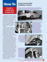
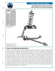
- Page 7 and 8: Installing SuspensionNote: The phot
- Page 9 and 10: The balljoint is then screwed into
- Page 11 and 12: Thread the balljoint in as far as p
- Page 13 and 14: Next, chase the threads in the lowe
- Page 15 and 16: If you have to remove the lower A-a
- Page 17 and 18: Next, install the shock simulator a
- Page 20: With the cotter pin installed, use
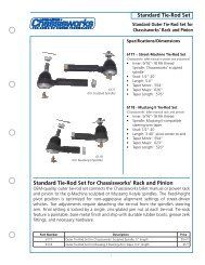
- Page 26 and 27: Install the tie rod end in the stee
- Page 28 and 29: First, check and record the camber
- Page 30 and 31: Next, set the bar level and tighten
- Page 32 and 33: Next, you can final assemble the ti
- Page 34 and 35: The caps are held in place with the
- Page 36 and 37: With both bushings on the bar, brin
- Page 38 and 39: Next, slide the link eyebolt onto t
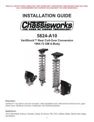
- Page 41 and 42: Screw the spring seat adjuster onto
- Page 43 and 44: Install the lower shock spud first.
- Page 45 and 46: Add a drop of Loctite to the thread
- Page 47 and 48: Pack the outer wheel bearing as you
- Page 49 and 50: Next, install the Wilwood brake cal
- Page 51 and 52: Use a 3/8” wrench to tighten the
- Page 53 and 54:
Move the spindle to full right lock
- Page 55 and 56:
Insert one urethane bushing into ea
- Page 57 and 58:
These optional stainless steel "spu
- Page 59 and 60:
Installing Manual Transmission,Clut
- Page 61 and 62:
Item 5916-F20-03 Turbo 400, 200-4R,
- Page 63 and 64:
After you remove the engine, place
- Page 65 and 66:
Use vise grip pliers and an end wre
- Page 67 and 68:
Disconnect the clamps that attach t
- Page 69 and 70:
Remove the bolts that attach the en
- Page 71 and 72:
You need three people; one to opera
- Page 73 and 74:
Lower the clip to the ground and pu
- Page 75 and 76:
This is the correct orientation of
- Page 77 and 78:
Place the top part of the mid and r
- Page 79 and 80:
Install the lower half of the rear
- Page 81 and 82:
Measure from the lip on the rocker
- Page 83 and 84:
Attach the stock hook rod to the pa
- Page 85 and 86:
Install two 1/2” self-locking set
- Page 87 and 88:
Slide the splined end of the u-join
- Page 89 and 90:
This is a photo of the completed in
- Page 91 and 92:
Drill a 1/8” hole centered in the
- Page 93 and 94:
Drill the remaining rivet holes sta
- Page 95 and 96:
Installing HeadersSpecial Note: We
- Page 97 and 98:
Installing SubframeConnectorsThe su
- Page 99 and 100:
Once you have all the bolts removed
- Page 101 and 102:
The spring clips can be just as tri
- Page 103 and 104:
Slide a 3/8 inch flat washer over t
- Page 105 and 106:
Page 104 917703