Installation Instructions - Chris Alston's Chassisworks
Installation Instructions - Chris Alston's Chassisworks
Installation Instructions - Chris Alston's Chassisworks

Create successful ePaper yourself
Turn your PDF publications into a flip-book with our unique Google optimized e-Paper software.
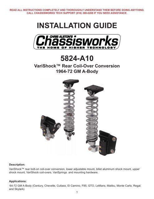
4DRIVER SIDE SHOWN
INSTRUCTIONS1. Before starting measure the height ofthe rear wheel well opening from theground on the driver and passengersides. Record these dimensions.This measurement will be used as areference to adjust the height of thelower billet shock mount and verify thatthe ride height is set correctly.2. Measure from the center of theaxle to the fender lip. Record thesemeasurements.It may be easier to accurately measurefrom the center of the axle to theground. This measurement can besubtracted from the previous fender-lipto ground measurement to calculate theneeded dimension.This information provides a referencepoint to correctly position rearendhousing once the vehicle is off theground and the wheels are removed.6
3. Jack the car up and place two jackstands under the frame just in front ofthe lower control arm mounts. The carmust be high enough to fully extend theshock to remove the OEM coil springs.4. Remove the wheels and tires.5. Keep the fl oor jack under the center onthe rear end housing to hold it up whileremoving the shocks.6. Remove the two bolts at the top eye ofeach factory shock.7. Unbolt the cantilever pin at the factorylower shock eye.7
8. Lower the rear end down until the coilsprings are loose.NOTE: On 1964-67 models you willneed to remove the bolt, washer andspacer used to position the spring on thehousing mounting plate.9. Remove the coil springs.10. Place the upper shock mount intoposition, aligning it with the factoryshock mounting holes.(Passenger side shown; use 7961-013)8
11. Bolt the upper coil-over mount to thedriver side OEM shock mount framebracket using the 5/16-18 x 1” sockethead cap screws, fl at washers andlocknuts supplied.12. Tighten the two bolts installed in thefactory shock mount holes before drillingthe new holes.13. Using the upper mount bracket as aguide, drill the two additional 5/16”diameter holes in the OEM shock mountbracket.DRILL HOLES FORSPECIFIC YEAR SPANNOTE: The required drilled holes aredifferent for the 1964-67 and 1968-72models.‘64-67&‘68-72‘68-72‘64-679
14. Secure the upper mount with twoadditional 5/16-18 x 1” socket head capscrews, fl at washers and locknuts.15. The upper mount is complete. Repeatthis procedure on the opposite side ofthe car.16. Place jack stands under the rearend housing so it is in the ride heightposition. Use the measurementsrecorded early to position the housing atthe correct height in relation to the wheelwell opening.17. Using the 1/2-13 x 1-1/4” bolts, fl atwashers and locknuts supplied, bolt thelower coil-over mount to the lower shockbracket on the housing. The lower holeof the bolt-on bracket will align with thefactory shock mounting hole.10
18. Align the top edge on the coil-overmount parallel to the axle tube, using alevel as shown.19. Tighten the 1/2” bolt securing the coilover bracket to the OEM shock mount.20. Use a clamp to hold the mount in placewhile drilling a second mounting hole.21. Using the mount as a guide drill a 1/2”diameter hole through the OEM bracketas shown.11
22. Secure the mount to the housing bracketwith a second 1/2-13 x 1-1/4” bolt, pairof fl at washers, and locknut. Torque bothbolts to 45 lb-ft.23. Drill a 5/16”-diameter hole through thecoil-over mount and housing bracket.24. Secure the mount with a5/16-18 x 1-1/4” bolt, fl at washers andlocknut. Torque to 25 lb-ft.12
25. Remove the rear lower control arm boltsat the rear end housing bracket.26. Slide the gusset bracket (7961-020)behind the lower coil-over mount andalong side the lower control bracket onthe housing.27. Bolt the gusset to the coil-over mountbracket with two 5/16-18 x 1-1/4” bolts,fl at washers and locknuts. DO NOT fullytighten the bolts at this time.28. Use the 1/2” fender washers as shims totake up any space between the gussetand the control arm mount.13
29. Insert the 1/2-13 x 4-1/4” hex boltthrough the housing brackets andcontrol arm.30. Secure the assembly with a fl at washerand 1/2” locknut. Torque to 45 lb-ft.31. Tighten the 5/16” bolts and torque to20 lb-ft.32. The lower coil-over mount is installed.Repeat this procedure on the oppositeside of the car before installing the coilovershock.14
Before proceeding, the rearend housingmust be positioned to match the centerof-axleto fender-lip measurment takenearlier.33. Slide the billet shock mount into the coilovermount as shown. Measure from theupper coil-over mount shock hole down13-1/2”. This is the location of the billetshock mount hole at the shock’s centerof-travelheight.34. Move the billet mount to the closestposition to the 13-1/2” length.35. Secure the billet mount with the 3/8”bolts, aircraft washers, and locknutsprovided.36. Tighten the bolts and torque to 35 lb.-ft.15
37. Install the coil-over shock between theupper and lower mounts WITHOUT thecoil spring installed.38. Place one shock spacer on each sideof the shock’s COM bearing. Thecounterbore of each spacer will seataround the end of the bearing sleeve.39. Slide a fl at washer over the1/2-20 x 2-1/2” hex bolt and insertit through the upper mount bracket,spacers, and shock bearing.40. Place a second fl at washer onto the boltfollowed by a locknut.SPACERS41. Tighten and torque to 55 lb-ft.16
42. The upper mount and coil-over shockare installed.43. Place one shock spacer on each side ofthe shock’s COM bearing, and align withthe billet lower shock mount.44. Secure the lower eye of the shock usinga 1/2” bolt and locknut.17
45. Torque to 45 lb-ft.46. Repeat the above on the opposite sideof the vehicle.47. Move the rear suspension through its complete range of shock travel, including full compression, fullextension, and full roll in both directions. There should be at least 1” of clearance between the shock bodyand the axle tube at all points.Full CompressionFull ExtensionFull Roll18
48. Once the clearance is checked you can installthe coil springs on the shocks using the VAS-200 spring compressor. Follow the instructionsincluded with the compressor.49. Re-install the coil-overs with springs and torquethe bolts to 45 lb-ft.VariShock Air SpringsAdditional clearance checks are required wheninstalling air springs.• Clearance around the top of the shock forthe port and for the air line to be safelyrouted around any exhaust components ormoving parts.• Clearance around the air bag, including theaxle tube, brake/fuel lines, and exhaust.19
50. With the weight on the coil-overs the center tocenter dimension on the shock should be 13-1/2” to13-5/8”. Follow the information included with yourshock to fi ne tune the coil-over ride height.51. Set the car on the ground and check the distancefrom the center on the axle to the wheel wellopenings they should match the measurementsrecorded earlier.Do not adjust the spring seat to alter ride heightmore than 1/2”. Instead, changing the position ofthe lower billet shock mount should be used tomake ride height adjustments of 1/2” or greater.VERIFY RIDE HEIGHT (AIR SPRINGS)After all suspension clearances have been checked and the shocks installed onto the vehicle, you must verify that theshocks rest at ride height within their allowable range of operation.• The suspension must carry the full weight of the complete vehicle, including interior and passenger weight, with thewheels on the ground during measurement.• Measure the length of the shock and compare to Air-Spring Shock Specifi cations chart to ensure you are within theRide Height range. Air pressure will need to be adjusted until both shocks measure equal to each other and are at thecorrect length.Air-Spring-Shock Ride-Height SpecificationsMounting Total Compressed Extended Ride Height* PortPart NumberAir-Bag StyleUpper Lower Travel Length 1 Length 1 Min. Max. LocationVAS 131K2-515 Poly Poly 5.00 11.56 16.56 13.56 14.56 Cap 4” Tapered Sleeve* Shock length is the measured distance between centers of mounting eyes.20
VERIFY RIDE HEIGHT (COIL-OVERS)After all suspension clearances have been checked and the shocks installedonto the vehicle with the springs, you must verify that the shocks rest at rideheight within their allowable range of operation.• The suspension must carry the full weight of the complete vehicle,including interior and passenger weight, with the wheels on the groundduring measurement.• Measure the length of the shock and compare to Shock Specifi cationschart to ensure you are within the Ride Height range. Spring preload willneed to be adjusted at the lower spring seat until both shocks measureequal to each other and are at the correct length.• SUSPENSION MUST BE AT FULL EXTENSION AND THE VEHICLESAFELY SUPPORTED WHILE ADJUSTING THE LOWER SPRING SEAT.• With the vehicle weight carried by the suspension, it is easier to get anaccurate measurement from the bottom of the upper spring seat to thecenter of the lower mounting bolt.• DO NOT THREAD THE LOWER SPRING SEAT UPWARD MORE THAN1/2” FROM IT’S LOWEST POSITION.• If more than 1/2” of preload is needed to raise the vehicle into the correctride height range, you must step up to a heavier spring rate. Failure toincrease the spring rate will allow the spring to abruptly coil-bind before fullshock compression, limit suspension travel, and damage the shock andrelated chassis and suspension components.Bottomof UpperSpringSeat11.43” to12.46”Ride-HeightLengthCenterof MountEyeCoil-Over-Shock Ride-Height SpecificationsMountingTotal Compressed Extended Ride Height* SpringPart NumberUpper Lower Travel Length* Length* Min. Max. LengthVAS 11X11-515 COM-8 COM-8 5.15” 9.37” 14.52” 11.43” 12.46” 12”* Shock length is measured from the top of the coil spring to the top surface of the lower crossbar tab. It is easiest to measure betweenthese two points once the shock has been mounted to the vehicle.Spring Selection GuidelinesA good spring rate baseline for passenger vehicles is 200 lb./in.Differences that alter desired spring rate:Weight Reduction -50 lbsRoad Race +50 lbs (better handling)Drag Race -50 lbs (more stored energy)Spring rate effects ride quality, ride height and roll ratecharacteristics. Differences in vehicles such as aluminum enginecomponents, fi berglass body parts and chassis stiffening should betaken into consideration. Additional springs can be purchased fortuning purposes.12” VariSpringsRate(lb/in)Part Number110 VAS 21-12110130 VAS 21-12130150 VAS 21-12150175 VAS 21-12175200 VAS 21-12200250 VAS 21-12250300 VAS 21-12300350 VAS 21-12350400 VAS 21-1240021
Determining Your Baseline Spring RateDetermining the correct spring rate and correctly adjusting your suspension is very important to achievingthe best possible and most reliable performance from your components. In fact, the vast majority of problemspeople experience with coil-over shocks can be attributed to using the wrong spring rate or incorrectadjustment of the shocks many settings.What is the Baseline Spring Rate?“Baseline spring rate” is defi ned as the pound-per-inch rate (lb/in) at which the spring supports the cornerweight of the vehicle with the coil-over shock at the correct installed height without the need to preload thespring. Once the baseline spring rate has been established, the vehicles performance goals and further testingwill reveal the correct fi nal spring rate for each installation. Differences such as how the spring is mounted(installation motion ratio), vehicle weight reduction, chassis stiffening, specifi c performance application, anddriver preference and skill level all have a bearing upon the correct fi nal spring rate.Where to Begin? (Initial Spring Rate)Based on our experience with vehicles and performance applications similar to your own, <strong>Chassisworks</strong> canrecommended an “initial spring rate” to install on your vehicle, from which the correct baseline spring ratecan be derived. In many cases our recommended initial spring rate will be the correct baseline spring rate.However, due to the sheer number of variables, it is impossible for our technical staff to predict the precisebaseline spring rate for each and every installation scenario. To assist you in obtaining the correct spring rate,a second set of springs can be purchased at a discount.Taking Measurements<strong>Chassisworks</strong> has developed a simple method to determine the correct baseline spring rate. This methodrequires installation of our initially recommendedspring, followed by a couple quick measurementsand some simple calculations. Before gettingstarted, the vehicle must be 100% complete. Thisincludes interior, glass, fluids, weight ballasts,and sand bags or free weights to substitute asthe weight of the driver. At this point, the springsshould already be installed on the shocks withNO PRELOAD and ready to go onto the vehicle.Lower spring seats should be just tight enough toremove free play from the spring.1. Record the initial spring rate as value “R” in thecalculation table that follows. Most VariSpringswill have the rate printed directly on them.2. With the shock fully extended, measure theinstalled free-length of the spring. At the upperspring-seatslot, hook the end of the tapemeasure against the spring and measure, withone sixteenth-of-an-inch accuracy, the distanceto the ground bottom edge of the spring.Record this dimension as value “F” in thecalculation table that follows.NOTE: The measured length may differslightly from the nominal spring length. In ourexample the 9” VariSpring actually measures8-15/16” when correctly installed.3. Install all shocks and springs onto the vehicleand lower it to the ground.Hook the tape measure against thespring at the upper spring seat slot.Measure the bottom end of the spring.2211-15/16”
1. Verify that the springs are supporting the full weight of the vehicle. Any chassis or shock bump stops thatare in contact must be temporarily removed. Make sure to replace bump stops when fi nished.2. Measure the springs again at their newly collapsed installed height to within one sixteenth-of-an-inchaccuracy from the same spring reference points used previously. Record this dimension as value “L” in thecalculation table that follows.Installed Height by PerformanceWhen a shock is at installed length (ride height) a certain amount of travel is available in either direction.Depending upon performance application, shock travel will be reserved in different percentages for bump(shock compressing) and rebound (shock extending). Use the Reserved Shock Travel Percentage Guidelinesand appropriate chart to determine the amount of bump travel required to collapse the shock to the correctinstalled length for your performance application. Record this dimension as value “T” in our calculations.NOTE: In our example calculation, a handling performance application with a 4.25”-travel coil-over shock listsa “T” value of 2.13.Perform the CalculationsCalculation TableThe leftmost column in the calculation table gives you a place to record your values. Use a pencil in case youmake a mistake.Record Values Variable Description__ __.__ __ F measured initial Free length of installed unloaded spring__ __.__ __ L measured Loaded spring compressed lengthF - L Answer 1 Subtract L from F__ __ __ lb/in R initial spring Rate in pounds per inchAnswer 1 x R Answer 2 Multiply Answer 1 by R__ __.__ __Answer 2 ÷ TTBASELINEspring Travel to achieve desired ride height (from chart on pg.13)SPRING RATE Divide Answer 2 by T =Example:Measured free length (F) 8-15/16” or 8.94Minus measured loaded length (L) 6-1/2” or 6.508.94F - 6.50L = 2.44Multiply that answer by the current spring rate 500 lb/in2.44 x 500R = 1220Divide that answer by the correct (T) value in chart1220 ÷ 2.13T = 572.77BRound the fi nal answer up or down to a suitable spring rate.( F - L ) RTBaselineSpring Rate23
Reserved Shock Travel Percentage GuidelinesStreet Baseline: 60-percent Bump, 40-percent ReboundStreet vehicles require more available compression (bump) travel for improved ride quality and unexpectedroad hazards. At baseline ride height, the shock and spring should collapse 40-percent from their installedheights. This results in 40-percent of travel available for extension and 60-percent for compression travel.Handling Baseline: 50-percent Bump, 50-percent ReboundHandling performance applications are usually limited to smooth prepared road-course- or autocross tracks,therefore less compression travel is required. Suspension geometry or track conditions may require the travelpercentages to be shifted to prevent topping- or bottoming-out the shock.Drag Race Baseline: 40-percent Bump, 60-percent ReboundDrag race vehicles generally require more extension (rebound) travel to help weight transfer, and becausethe drag strip is very fl at, less compression travel is needed. The amount of extension travel available in theshock will drastically affect how the car works. At baseline ride height, the shock and spring should collapse 60-percent from their installed heights. This results in 60-percent of travel available for extension and 40-percent ofcompression travel.Optionally, it is acceptable to adjust the shock’s installed height to any length between the minimum andmaximum spring-length value shown in the chart. This range allows you to adjust the vehicle ride height a smallamount by using the threaded lower spring seat.VariShock Coil-Over ShocksCoil-Over Street Handling Drag Spring Street Handling DragShock 60/40 50/50 40/60 Free Max. Center Min.Travel (T) Spring Travel Used At Ride Height Length Installed Spring Length At Ride Height5.15 2.06 2.58 3.09 12 9.94 9.43 8.91WARRANTY NOTICE:There are NO WARRANTIES, either expressed or implied. Neither the seller nor manufacturer will be liable for any loss, damageor injury, direct or indirect, arising from the use or inability to determine the appropriate use of any products. Before any attemptat installation, all drawings and/or instruction sheets should be completely reviewed to determine the suitability of the product forits intended use. In this connection, the user assumes all responsibility and risk. We reserve the right to change specifi cationwithout notice. Further, <strong>Chris</strong> Alston’s <strong>Chassisworks</strong>, Inc., makes NO GUARANTEE in reference to any specific class legality of anycomponent. ALL PRODUCTS ARE INTENDED FOR RACING AND OFF-ROAD USE AND MAY NOT BE LEGALLY USED ON THEHIGHWAY. The products offered for sale are true race-car components and, in all cases, require some fabrication skill. NO PRODUCTOR SERVICE IS DESIGNED OR INTENDED TO PREVENT INJURY OR DEATH.<strong>Chris</strong> Alston’s <strong>Chassisworks</strong>8661 Younger Creek DriveSacramento, CA 95828Phone: 916-388-0288Technical Support: sales@cachassisworks.com7951-5824A1024REV 09/23/10