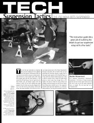
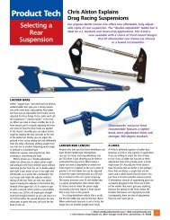
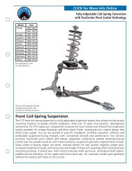
Determining Your Baseline Spring RateDetermining the correct spring rate and correctly adjusting your suspension is very important to achievingthe best possible and most reliable performance from your components. In fact, the vast majority of problemspeople experience with coil-over shocks can be attributed to using the wrong spring rate or incorrectadjustment of the shocks many settings.What is the Baseline Spring Rate?“Baseline spring rate” is defi ned as the pound-per-inch rate (lb/in) at which the spring supports the cornerweight of the vehicle with the coil-over shock at the correct installed height without the need to preload thespring. Once the baseline spring rate has been established, the vehicles performance goals and further testingwill reveal the correct fi nal spring rate for each installation. Differences such as how the spring is mounted(installation motion ratio), vehicle weight reduction, chassis stiffening, specifi c performance application, anddriver preference and skill level all have a bearing upon the correct fi nal spring rate.Where to Begin? (Initial Spring Rate)Based on our experience with vehicles and performance applications similar to your own, <strong>Chassisworks</strong> canrecommended an “initial spring rate” to install on your vehicle, from which the correct baseline spring ratecan be derived. In many cases our recommended initial spring rate will be the correct baseline spring rate.However, due to the sheer number of variables, it is impossible for our technical staff to predict the precisebaseline spring rate for each and every installation scenario. To assist you in obtaining the correct spring rate,a second set of springs can be purchased at a discount.Taking Measurements<strong>Chassisworks</strong> has developed a simple method to determine the correct baseline spring rate. This methodrequires installation of our initially recommendedspring, followed by a couple quick measurementsand some simple calculations. Before gettingstarted, the vehicle must be 100% complete. Thisincludes interior, glass, fluids, weight ballasts,and sand bags or free weights to substitute asthe weight of the driver. At this point, the springsshould already be installed on the shocks withNO PRELOAD and ready to go onto the vehicle.Lower spring seats should be just tight enough toremove free play from the spring.1. Record the initial spring rate as value “R” in thecalculation table that follows. Most VariSpringswill have the rate printed directly on them.2. With the shock fully extended, measure theinstalled free-length of the spring. At the upperspring-seatslot, hook the end of the tapemeasure against the spring and measure, withone sixteenth-of-an-inch accuracy, the distanceto the ground bottom edge of the spring.Record this dimension as value “F” in thecalculation table that follows.NOTE: The measured length may differslightly from the nominal spring length. In ourexample the 9” VariSpring actually measures8-15/16” when correctly installed.3. Install all shocks and springs onto the vehicleand lower it to the ground.Hook the tape measure against thespring at the upper spring seat slot.Measure the bottom end of the spring.2211-15/16”
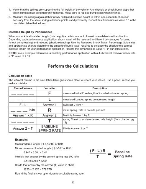
1. Verify that the springs are supporting the full weight of the vehicle. Any chassis or shock bump stops thatare in contact must be temporarily removed. Make sure to replace bump stops when fi nished.2. Measure the springs again at their newly collapsed installed height to within one sixteenth-of-an-inchaccuracy from the same spring reference points used previously. Record this dimension as value “L” in thecalculation table that follows.Installed Height by PerformanceWhen a shock is at installed length (ride height) a certain amount of travel is available in either direction.Depending upon performance application, shock travel will be reserved in different percentages for bump(shock compressing) and rebound (shock extending). Use the Reserved Shock Travel Percentage Guidelinesand appropriate chart to determine the amount of bump travel required to collapse the shock to the correctinstalled length for your performance application. Record this dimension as value “T” in our calculations.NOTE: In our example calculation, a handling performance application with a 4.25”-travel coil-over shock listsa “T” value of 2.13.Perform the CalculationsCalculation TableThe leftmost column in the calculation table gives you a place to record your values. Use a pencil in case youmake a mistake.Record Values Variable Description__ __.__ __ F measured initial Free length of installed unloaded spring__ __.__ __ L measured Loaded spring compressed lengthF - L Answer 1 Subtract L from F__ __ __ lb/in R initial spring Rate in pounds per inchAnswer 1 x R Answer 2 Multiply Answer 1 by R__ __.__ __Answer 2 ÷ TTBASELINEspring Travel to achieve desired ride height (from chart on pg.13)SPRING RATE Divide Answer 2 by T =Example:Measured free length (F) 8-15/16” or 8.94Minus measured loaded length (L) 6-1/2” or 6.508.94F - 6.50L = 2.44Multiply that answer by the current spring rate 500 lb/in2.44 x 500R = 1220Divide that answer by the correct (T) value in chart1220 ÷ 2.13T = 572.77BRound the fi nal answer up or down to a suitable spring rate.( F - L ) RTBaselineSpring Rate23