How To Install a Ladder-Bar Suspension - Chris Alston's Chassisworks
How To Install a Ladder-Bar Suspension - Chris Alston's Chassisworks
How To Install a Ladder-Bar Suspension - Chris Alston's Chassisworks
- No tags were found...

You also want an ePaper? Increase the reach of your titles
YUMPU automatically turns print PDFs into web optimized ePapers that Google loves.
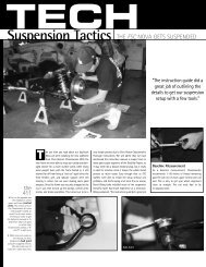
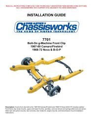
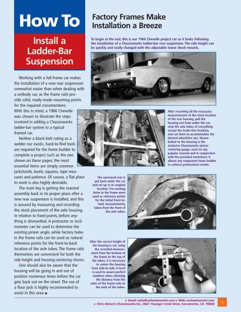
<strong>How</strong> <strong>To</strong><strong>Install</strong> a<strong>Ladder</strong>-<strong>Bar</strong><strong>Suspension</strong>Factory Frames Make<strong>Install</strong>ation a Breeze<strong>To</strong> begin at the end, this is our 1966 Chevelle project car as it looks followingthe installation of a <strong>Chassisworks</strong> ladder-bar rear suspension. The ride height canbe quickly and easily changed with the adjustable lower shock mounts.Working with a full-frame car makesthe installation of a new rear suspensionsomewhat easier than when dealing witha unibody car, as the frame rails providesolid, ready-made mounting pointsfor the required crossmembers.With this in mind, a 1966 Chevellewas chosen to illustrate the stepsinvolved in adding a <strong>Chassisworks</strong>ladder-bar system to a typicalframed car.Neither a black-belt rating as awelder nor exotic, hard-to-find toolsare required for the home builder tocomplete a project such as the oneshown on these pages; the mostessential items are simply commonjackstands, levels, squares, tape measuresand patience. Of course, a flat placeto work is also highly desirable.The main key is getting the rearendassembly back in its proper place after anew rear suspension is installed, and thisis assured by measuring and recordingthe stock placement of the axle housing,in relation to fixed points, before anythingis dismantled. A protractor or inclinometercan be used to determine theexisting pinion angle, while factory holesin the frame rails can be used as naturalreference points for the front-to-backlocation of the axle tubes. The frame railsthemselves are convenient for both theride-height and housing-centering chores.One should also be aware that thehousing will be going in and out ofposition numerous times before the cargets back out on the street. The use ofa floor jack is highly recommended toassist in this area ▪The narrowed rear isput back under the carand set up in its originallocation. Pre-existingholes in the frame wereused as reference pointsfor the initial front-tobackmeasurements,taken from the front ofthe axle tubes.After the correct height ofthe housing is set, usingthe recorded measurementfrom the bottom ofthe frame to the top ofthe tubes, it is necessaryto center the housingfrom side-to-side. A levelis used to assure perfectnumbers when checkingthe distance from thesides of the frame rails tothe ends of the tubes.After recording all the necessarymeasurements of the stock locationof the rear housing, pull thehousing out from under the car,strip the axle tubes of everythingexcept the brake-line brackets,and cut them to accommodate thedesired wheel/tire size. Shownbolted to the housing is theexclusive <strong>Chassisworks</strong> pinioncenteringgauge; used on anypopular rearend and in conjunctionwith the provided worksheet, itallows any competent home builderto achieve professional results. Email: sales@cachassisworks.com Web: cachassisworks.com <strong>Chris</strong> Alston’s <strong>Chassisworks</strong> Inc., 8661 Younger Creek Drive, Sacramento, CA 958281
A protractor or an inclinometer set across the front of theyoke will reveal the initial pinion angle, and an adjustablejack stand comes in handy for returning the now-free-floatinghousing to its stock attitude.After cutting the crossmember to size, the front ladder-bar bracketsare set in their proper, as-wide-as-possible locations and tacked inplace. (The minimum clearance from the brackets to the frame is 1-1/2 inches.) The steel sleeves that ride in the middle of the urethanebushings are used to establish the correct spacing for the brackets.Using materialprovided in thekit, gusset strapsare fabricated andwelded to the backof the bracketsfor added strength.<strong>To</strong> determine the location of the front crossmember, measurethe prescribed distance forward from the housing and make amark on the frame rails. Next, measure the distance betweenthe rails at this point, noting the exact location of the driveshaftcenterline.This is how theChevelle’s fullywelded front crossmemberlooked justprior to its finalinstallation. Notethe contour on theend of the tubing.These measurementsare then transferred tothe dropped-loopcrossmember, which ismarked for cutting. Labelingthe driver and passengersides of the crossmemberwill help in maintaining itsproper orientation, keepingthe loop centered underthe driveshaft. Be sureto cut the ends of thetubing to follow thecontour of the rails, if any.With their assignments as spacers for the brackets completed,the steel sleeves are returned to their intendedhomes in the middle of the urethane bushings.Don’t bereluctant to sneakup on the perfectcrossmember lengthby making a seriesof small cuts on thetubing. A snug fit ishelpful for the finalalignment.This is the last time the crossmember will be seen in thedaylight. With the ladder bars assembled and mounted tothe crossmember, the entire unit slides under the car andis lifted into place, with the rear brackets snug to the axletubes. This is where a tight fit for the crossmember willcome in handy, to help hold itself in position.2 Order: 800-722-2269 Technical Assistance/Customer Service: 916-388-0288 <strong>Chris</strong> Alston’s <strong>Chassisworks</strong> Inc., 8661 Younger Creek Drive, Sacramento, CA 95828
Bumping the brackets into the housing will undoubtedly jostle it around;all measurements must be rechecked before firing up the welder.The housing is brought back out from under the car and the ladderbars are removed from the brackets. The ears at the top of the housing,used for mounting the stock link bars, will be removed to provideclearance for the panhard bar.With clamps holding the front crossmember in place, the rear bracketsare checked for plumb and tacked to the housing.Again, the steel sleeves from the urethane bushings are used asspacers, and the brackets are welded to the axle tubes. <strong>Chassisworks</strong>recommends also welding the tubes to the housing for added strength.With the brackets welded to the tubes and gusset straps added,the housing and ladder bars are remounted under the car. Theshock is then assembledin the center position ofthe adjustable lowershock-mounting plate,which is held in itsdesired location andmarked for cutting.Constant use of a tape measureis critical to ensure the successof any chassis or suspensioninstallation. Here, the distancebetween the brackets isverified after they are tackedto the housing.With the rear brackets tackedin place, and after making sureeverything is straight and square,the front crossmember is tacked tothe frame. The ladder bars are thenremoved from the front brackets,and the crossmember iswelded to the frame. Email: sales@cachassisworks.com Web: cachassisworks.com <strong>Chris</strong> Alston’s <strong>Chassisworks</strong> Inc., 8661 Younger Creek Drive, Sacramento, CA 958283
The universal lowershockmounting plateis then cut along theline to fit on the backof the rear ladder-barbracket.These are the pieces included in the <strong>Chassisworks</strong> panhard-barkit. One end of the bar and one of the rod ends are threaded foradjustment; the other rod end is welded in place. The bracket atthe lower left is attached to the axle tube.After tacking the plate tothe ladder-bar bracket,make sure it is straightand plumb before finalwelding.The tubing for theupper shock-mountcrossmember is cut to fitbetween the frame railsand positioned with theuse of levels and shocksimulators, with theadjustable shock mountsset at their highestlevel. Once again steelsleeves, fabricated fromtubing for the uppershock mounts, are usedto establish the properbracket spacing.The non-threaded end of the panhard bar is marked for cutting tothe desired length. The housing must be properly centered whendetermining the correct bar length.Seen here are the installed uppershock-mount crossmember andthe panhard bar, which spans thedistance from the frame on theleft side to the axle housing onthe right. Make certain that thepanhard-bar bracket on the housingclears the frame rails.This is the fully fabricated upper shock-mount crossmember,prior to installation. The tabs on the ends of the tube wereadded to allow the crossmember to sit as high as possiblebetween the frame rails, while still providing a sufficientamount of surface for welding.The shocks are installed withoutthe springs, and all clearances arechecked at both full compressionand full extension to make surenothing binds up. Clearly visible isthe extra brace welded betweenthe lower shock-mounting plateand the housing.4 Order: 800-722-2269 Technical Assistance/Customer Service: 916-388-0288 <strong>Chris</strong> Alston’s <strong>Chassisworks</strong> Inc., 8661 Younger Creek Drive, Sacramento, CA 95828
With clamps holdingeverything in place,the stock housingend is welded backonto the axle tube.Don’t forget to remount the pads for the rubber axle snubbersonto both sides of the housing, directly below the frame rails, tokeep the shocks from bottoming out and beating themselves up.The housing endsare fully welded,and the entireassembly is backin place. Visibleare the notchesthat had to becut into the stockcrossmember toallow full ladderbartravel, andthe lower shockmountgussets.With all necessary brackets attached to the housing, it’s time tocomplete the narrowing procedure; <strong>Chassisworks</strong> carries the partsneeded for the home builder to do the job. The pinion centerlinegauge, foreground, is machined to work with all types of housings,while the alignment bar, carrier adapters (left), and housing-endadapter provide absolute precision when welding the ends in place.Lacking only the brake backing plates and a bit of paint, theladder-bar installation is virtually complete, with the panhardbarbracket clearly visible. The bearing-mounting areas ofthe stock housing ends have been cut off to allow the use ofthe Strange safety hubs, which are bolted to the housing-endflange from the inboard side and contain their own bearings,eliminating the potentially hazardous C-clip methodof holding the axles in place.The alignment bar slides into the housingand through the carrier-bearing adapters,which are installed in place of the carrierbearings. The housing-end adapter fitssnugly into the bearing area of the stockhousing end (which was cut off a coupleof inches from the backing-plate mountingflange), holding the end perfectly square tothe pinion.L60-15 tires on 15x8-inchrims put a full 22 inchesof rubber on the groundas the Chevelle returnedto earth. Visible on theright side of the photois one of the additionalgussets (formed from thecut-off ends of the frontcrossmember) that runsfrom the crossmemberto the frame.<strong>How</strong><strong>To</strong>-001_0204 Email: sales@cachassisworks.com Web: cachassisworks.com5 <strong>Chris</strong> Alston’s <strong>Chassisworks</strong> Inc., 8661 Younger Creek Drive, Sacramento, CA 95828