PDF File
PDF File
PDF File

Create successful ePaper yourself
Turn your PDF publications into a flip-book with our unique Google optimized e-Paper software.
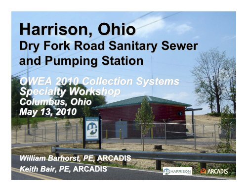
Harrison, Ohio<br />
Dry Fork Road Sanitary Sewer<br />
and Pumping Station<br />
OWEA 2010 Collection Systems<br />
Specialty Workshop<br />
Columbus, Ohio<br />
May 13, 2010<br />
William Barhorst, PE, ARCADIS<br />
Keith 1 Bair, PE, ARCADIS
Presentation Outline<br />
Master Planning<br />
• Service Area or Study Area<br />
• Land Use<br />
• Existing Collection System Mapping<br />
• Future Sewers<br />
Dry Fork Trunk Sewer Design<br />
• Phase 1 – Gravity Sewer, Force Main<br />
and Pump Station<br />
• Phase 2 – Gravity Sewer<br />
2
Master Planning – Define Service Area<br />
Service Area of Study included:<br />
• City of Harrison<br />
(incorporated area)<br />
• West Harrison<br />
• Harrison Township<br />
• I-74 corridor in Indiana<br />
• Annexed portion of<br />
Crosby Township<br />
• Highly probable area of<br />
residential development in<br />
Crosby Township<br />
neighboring City of Harrison<br />
3
Master Planning – Delineate Land Use<br />
• Delineate Existing and<br />
Planned Land use:<br />
• Industrial<br />
• Commercial<br />
• Residential – High Density<br />
• Residential – Medium Density<br />
• Rural<br />
• Greenspace<br />
• Floodplain<br />
• Special (No flow)<br />
• Determine areas deemed too<br />
remote or sparsely developed for<br />
centralized sewer collection<br />
• Attribute flow generation by<br />
land use<br />
4
Master Planning – Map Collection System<br />
• Sewer Atlas<br />
• GIS useful for database<br />
construction<br />
― Existing record drawings<br />
― Field survey<br />
• Delineate Collection System<br />
into sewer drainage basins<br />
• Dry Fork Basin has 5,100 acres<br />
with 2,400 acres generating<br />
wastewater<br />
5
Master Planning –<br />
Identify Future Sewer Needs<br />
WEST RD<br />
HUBERT INDUSTIES<br />
PUMP STATION<br />
I-74<br />
DRY FORK RD<br />
SHORT RD<br />
• Extend sewer service into<br />
Dry Fork Basin with new<br />
trunk sewer<br />
• Relieve West Road / I-74<br />
Trunk Sewer<br />
• Plan for gravity sewers in areas<br />
of high density<br />
• Plan for alternative sewer<br />
systems where gravity sewers<br />
aren’t feasible<br />
• Collection system modeling<br />
useful for sewer sizing and<br />
recognizing capacity issues<br />
6
Design Criteria – Dry Fork Trunk Sewer<br />
• Projected ADF = 1.5 MGD<br />
• Projected Peak = 4.5 MGD<br />
• Previous planning determined that a creek alignment was not<br />
feasible.<br />
• Most feasible alignment along Dry Fork Road resulted in:<br />
– 35 ft. deep gravity sewer in some sections<br />
– New pumping station north of West Road<br />
– Tunneling under I-74<br />
7
Dry Fork Phased Approach<br />
Phase 1<br />
• Construct upper end of trunk sewer to serve<br />
new residential developments<br />
• Dry Fork Pump Station<br />
• Force main to existing Hubert Industries Pump Station<br />
until Phase 2 trunk sewer can be installed<br />
Phase 2<br />
• Lower trunk sewer from Hubert Industries PS south<br />
to existing collection system<br />
• Convert wet well of Hubert Industries PS to manhole<br />
• Cross I-74 at Dry Fork Road<br />
• Local collector sewers<br />
8
Dry Fork<br />
Phase 1 Design<br />
4,060 LF 18"<br />
Sanitary Sewer<br />
4.5 MGD Pumping<br />
Station<br />
3,837 LF of 8"<br />
and 14" parallel<br />
Force Mains<br />
Phase 2 Trunk<br />
Sewer<br />
9
Phase 1 – Sanitary Sewer Design<br />
• Determine most favorable<br />
alignment considering:<br />
– Depth of bury<br />
– Creek crossings<br />
– Easement acquisition<br />
– Soil conditions<br />
• Average depth of bury: 25 ft.<br />
• Maximum depth of bury: 35 ft.<br />
• Adequate easement width<br />
obtained for excavation and<br />
future maintenance<br />
– Assume 1:1 side slopes<br />
10
Phase 1 – Sanitary Sewer Design<br />
• Tunneling (boring) selected at<br />
key locations<br />
– Reduce restoration costs<br />
– Save structures<br />
– Minimize easements<br />
• Creek crossings minimized and<br />
made perpendicular to creek<br />
• Keep alignment clear of creek<br />
riparian zone<br />
11
Phase 1 –<br />
Pumping Station Design<br />
Initial Conditions<br />
• 0.2 MGD ADF following first<br />
residential development<br />
• 0.6 MGD peak<br />
Ultimate Conditions<br />
• 1.5 MGD ADF<br />
• 4.5 MGD Peak<br />
12
Phase 1 – Pumping Station Design<br />
Wet Well<br />
• Divided wet well design<br />
– Use one wetwell for<br />
initial low flows<br />
– Reduce wetwell volume<br />
and pump cycle time<br />
– Easier maintenance<br />
• Minimize wet well detention<br />
times by adjusting pump<br />
control elevations<br />
• Design total wet well volume<br />
for future 4.5 MGD peak<br />
13
Phase 1 – Pumping Station Design<br />
Pump Selection<br />
• Select pumps with adequate turndown capability to meet initial<br />
low flows<br />
• Install pumps needed for next 5 to 7 years.<br />
Pumps that sit unused for long periods will have<br />
balance problems when needed.<br />
• Plan for pump additions and change-out as flows increase over<br />
time<br />
• Use VFDs to reduce initial pump flows to match influent flows<br />
• Size VFDs for future duty requirements<br />
14
Phase 1 – Pumping Station Design<br />
Pumping Strategy<br />
Avg / Peak (MGD)<br />
0.2 / 0.60<br />
0.4 / 1.2<br />
0.7 / 2.1<br />
1.0 / 3.0<br />
1.5 / 4.5<br />
# Pumps / Cap*<br />
1 / 520 gpm**<br />
2 / 520 gpm<br />
3 / 520 gpm<br />
2 / 1,040 gpm***<br />
3 / 1,040 gpm<br />
Wet wells Req’d<br />
1<br />
2<br />
2<br />
2<br />
2<br />
* Number of pumps for firm capacity, not including spare<br />
** VFD operation for normal pumping at 250 gpm<br />
*** Pump change-out required<br />
15
Phase 1 – Pumping Station Design<br />
Valve Vault Piping<br />
• Install all piping in<br />
valve vault for future needs<br />
• Installing future piping in<br />
other wet well is optional<br />
• If pump discharge piping<br />
and pump bases are<br />
installed in future wet well,<br />
size for largest future pump<br />
16
Phase 1 – Pumping Station Design<br />
Misc. Design Elements<br />
• Yard hydrant near wet well<br />
for washdown<br />
• Non-potable water pumping<br />
skid (OEPA required)<br />
• Floor space available for<br />
future chemical feed for<br />
odor control<br />
• Emergency shower and<br />
eye wash<br />
• Emergency power generator<br />
17
Phase 1 – Force Main Design<br />
• Dual force mains to<br />
accommodate wide flow range<br />
• 8 inch force main:<br />
up to 1.5 MGD<br />
• 14 inch force main:<br />
1.5 to 4.5 MGD<br />
• Install both force mains<br />
in common trench<br />
• Air release valves for both<br />
FMs installed in common<br />
manhole<br />
18
Dry Fork Phase 2<br />
• 8,000 LF 24" Sanitary Sewer<br />
at 0.09% slope<br />
• Convert Hubert Industries PS<br />
to manhole<br />
• Local Collector Sewers<br />
• Gas station at corner Dry Fork<br />
Road/Pilot Road<br />
• Commercial properties along<br />
Pilot Road<br />
• Cross I-74<br />
• Connect to existing collection<br />
on Simonson Road<br />
19
Aerial<br />
View<br />
20
Phase 2 Design – Conversion of<br />
Hubert Industries Pumping Station<br />
21
Phase 2 Design – I-74 Crossing<br />
Considerations<br />
• Selection of location for crossing<br />
• ODOT approval<br />
• Encasement pipe<br />
• Traffic maintenance in area of receiving<br />
pit on Pilot Road<br />
22
23<br />
Phase 2 Design – Location of I-74 I<br />
Crossing
24<br />
Phase 2 Design – Plan of I-74 I<br />
Crossing
Phase 2 Design – Alternative routes<br />
from Harrison Avenue to the corn field<br />
25
26<br />
Imagine the result