

69-2486-03 - TH8320ZW1000 Z-Wave Thermostat
69-2486-03 - TH8320ZW1000 Z-Wave Thermostat
69-2486-03 - TH8320ZW1000 Z-Wave Thermostat

You also want an ePaper? Increase the reach of your titles
YUMPU automatically turns print PDFs into web optimized ePapers that Google loves.
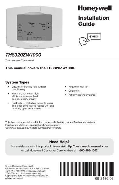
Installation<br />
Guide<br />
<strong>TH8320ZW1000</strong><br />
Touch-screen <strong>Thermostat</strong><br />
This manual covers the <strong>TH8320ZW1000</strong>.<br />
System Types<br />
• Gas, oil, or electric heat with air<br />
conditioning<br />
• Warm air, hot water, high<br />
efficiency furnaces, heat<br />
pumps, steam, gravity<br />
• Heat only — including power to open<br />
and close zone valves (Series 20), and<br />
normally open zone valves<br />
• Heat only with fan<br />
• Cool only<br />
• 750 mV heating systems<br />
This thermostat contains a Lithium battery which may contain Perchlorate material.<br />
Perchlorate Material—special handling may apply.<br />
See www.dtsc.ca.gov/hazardouswaste/perchlorate<br />
Need Help?<br />
For assistance with this product please visit http://customer.honeywell.com<br />
or call Honeywell Customer Care toll-free at 1-800-468-1502<br />
® U.S. Registered Trademark.<br />
US Patent No. 6,574,581, 6,975,958, 7,114,554,<br />
7,346,467, 7,636,604, 7,<strong>69</strong>3,582, 7,788,936,<br />
7,845,576, and other patents pending.<br />
Copyright © 2011 Honeywell International Inc.<br />
All rights reserved.<br />
<strong>69</strong>-<strong>2486</strong>-<strong>03</strong>
Installation Guide<br />
Wallplate installation<br />
1. Separate wallplate from thermostat.<br />
2. Mount wallplate as shown below.<br />
Grasp top and bottom of wallplate<br />
and pull to remove from thermostat.<br />
+ +<br />
Drill 3/16” holes for drywall.<br />
Drill 7/32” holes for plaster.<br />
+<br />
M29480<br />
Wire hole<br />
Mounting screws<br />
Wall anchors<br />
Must be installed by a trained, experienced technician<br />
• Read these instructions carefully. Failure to follow these instructions<br />
can damage the product or cause a hazardous condition.<br />
M29481<br />
CAUTION: ELECTRICAL HAZARD<br />
Can cause electrical shock or equipment damage. Disconnect power before beginning<br />
installation.<br />
MERCURY NOTICE<br />
If this product is replacing a control that contains mercury in a sealed tube, do not<br />
place the old control in the trash. Contact your local waste management authority for<br />
instructions regarding recycling and proper disposal.<br />
<strong>69</strong>-<strong>2486</strong>—<strong>03</strong><br />
2
Power Requirements<br />
<strong>TH8320ZW1000</strong><br />
Remove tab.<br />
K<br />
K<br />
Connect the common side of<br />
the transformer to “C” terminal.<br />
This connection is mandatory.<br />
M32428<br />
M32429<br />
The thermostat is shipped from the factory<br />
with the coin cell installed. To keep the<br />
battery from discharging during shipment<br />
and storage, the thermostat is shipped<br />
with a plastic tab inserted in the battery<br />
holder. This tab must be removed during<br />
installation. Simply pull the plastic tab<br />
out of the battery tray. Make sure that the<br />
battery tray is fully inserted into the thermostat.<br />
Wiring<br />
Remove factory-installed jumper<br />
only for two-transformer systems.<br />
Push excess wire back into the wall opening. Plug<br />
wall opening with non-flammable insulation.<br />
K<br />
K<br />
M32430<br />
M32431<br />
3 <strong>69</strong>-<strong>2486</strong>—<strong>03</strong>
Installation Guide<br />
Wiring<br />
Terminal Designations<br />
Conventional Terminal Letters:<br />
R<br />
Rc<br />
C<br />
W<br />
W2<br />
Y<br />
Y2<br />
G<br />
K<br />
Heating power. Connect to secondary<br />
side of heating system transformer.<br />
Cooling power. Connect to secondary<br />
side of cooling system transformer.<br />
Common wire from secondary side<br />
of cooling transformer (if 2 transformers).<br />
1st stage heat relay.<br />
2nd stage heat relay<br />
1st stage compressor contactor.<br />
2nd stage compressor contactor.<br />
Fan relay.<br />
Optional THP9045 Wiring Module<br />
Terminal [9]<br />
Heat Pump Terminal Letters:<br />
R Heating power. Connect to secondary<br />
side of heating system transformer.<br />
Rc Cooling power. Connect to secondary<br />
side of cooling system transformer.<br />
C Common wire from secondary side of<br />
cooling system transformer.<br />
Y 1st stage compressor contactor.<br />
Y2 2nd stage compressor contactor.<br />
Aux Auxiliary heat relay.<br />
G Fan relay.<br />
E Emergency heat relay.<br />
L Heat pump reset (powered continuously<br />
when System is set to Em Heat;<br />
system monitor when set to Heat,<br />
Cool or Off).<br />
O/B Changeover valve for heat pumps.<br />
K Optional THP9045 Wiring Module<br />
Terminal [9]<br />
1H/1C System (1 transformer)<br />
Rc Power [1]<br />
R [R+Rc joined by jumper]<br />
W Heat relay<br />
Y Compressor contactor<br />
G Fan relay<br />
C 24VAC common [3]<br />
K Optional THP9045 Wiring Module<br />
Terminal [9]<br />
Heat Only System<br />
Rc Power [1]<br />
R [R+Rc joined by jumper]<br />
W Heat relay<br />
C 24VAC common [3]<br />
Wiring guide—conventional systems<br />
Heat Only System (Series 20)<br />
Rc [R+Rc joined by jumper]<br />
R Series 20 valve terminal “R” [1]<br />
W Series 20 valve terminal “B”<br />
Y Series 20 valve terminal “W”<br />
C 24VAC common [3]<br />
2H/2C System (1 transformer)<br />
Y2 Cool relay 2<br />
W2 Heat relay 2<br />
Rc Power [1]<br />
R [R+Rc joined by jumper]<br />
W Heat relay 1<br />
Y Cool relay 1<br />
G Fan relay<br />
C 24VAC common [3]<br />
K Optional THP9045 Wiring Module<br />
Terminal [9]<br />
See [notes] below<br />
[1] Power supply. Provide disconnect means and overload protection as required.<br />
[3] Connection to 24VAC common at the transformer is required.<br />
[9] See "Optional THP9045 Wiring Module" on page 14 for more details.<br />
<strong>69</strong>-<strong>2486</strong>—<strong>03</strong><br />
4
Wiring<br />
Wiring guide—heat pump systems<br />
<strong>TH8320ZW1000</strong><br />
1H/1C Heat Pump (no auxiliary heat)<br />
Rc Power [1]<br />
R [R+Rc joined by jumper]<br />
O/B Changeover valve [5]<br />
Y Compressor relay<br />
G Fan relay<br />
C 24VAC common [3]<br />
K Optional THP9045 Wiring Module<br />
Terminal [9]<br />
2H/1C Heat Pump (with auxiliary heat)<br />
L Equipment monitor [6, 7]<br />
E Emergency heat relay [8]<br />
Aux Auxiliary heat relay (Heat 2) [8]<br />
Rc Power [1]<br />
R [R+Rc joined by jumper]<br />
O/B Changeover valve [5]<br />
Y Compressor relay<br />
G Fan relay<br />
C 24VAC common [3]<br />
K Optional THP9045 Wiring Module<br />
Terminal [9]<br />
2H/2C Heat Pump (no auxiliary heat)<br />
Y2 Compressor 2 relay<br />
Rc Power [1]<br />
R [R+Rc joined by jumper]<br />
O/B Changeover valve [5]<br />
Y Compressor 1 relay<br />
G Fan relay<br />
C 24VAC common [3]<br />
K Optional THP9045 Wiring Module<br />
Terminal [9]<br />
1H/1C System (2 transformers)<br />
Rc Power (cooling transformer) [1, 2]<br />
R Power (heating transformer) [1, 2]<br />
W Heat relay<br />
Y Compressor contactor<br />
G Fan relay<br />
C 24VAC common [3, 4]<br />
K Optional THP9045 Wiring Module<br />
Terminal [9]<br />
Heat Only System With Fan<br />
Rc Power [1]<br />
R [R+Rc joined by jumper]<br />
W Heat relay<br />
G Fan relay<br />
C 24VAC common [3]<br />
Cool Only System<br />
Rc Power [1]<br />
R [R+Rc joined by jumper]<br />
Y Compressor contactor<br />
G Fan relay<br />
C 24VAC common [3]<br />
K Optional THP9045 Wiring Module<br />
Terminal [9]<br />
2H/2C System (2 transformers)<br />
Y2 Cool relay 2<br />
W2 Heat relay 2<br />
Rc Power (cooling transformer) [1, 2]<br />
R Power (heating transformer) [1, 2]<br />
W Heat relay 1<br />
Y Cool relay 1<br />
G Fan relay<br />
C 24VAC common [3, 4]<br />
K Optional THP9045 Wiring Module<br />
Terminal [9]<br />
See [notes] below<br />
[1] Power supply. Provide disconnect means and overload protection as required.<br />
[2] Remove jumper for 2 transformer systems.<br />
[3] Connection to 24VAC common at the transformer is required.<br />
[4] Common connection must come from cooling transformer.<br />
[5] O/B set to control as either O or B in installer setup.<br />
[6] If L terminal is used, 24VAC common (terminal C) must be connected.<br />
[7] Heat pump reset (powered continuously when thermostat is set to Em. Heat; system monitor<br />
when set to Heat, Cool, or Off).<br />
[8] Install field jumper between Aux and E terminals if there is no emergency heat relay.<br />
[9] See "Optional THP9045 Wiring Module" on page 14 for more details.<br />
5 <strong>69</strong>-<strong>2486</strong>—<strong>03</strong>
Installation Guide<br />
Mount thermostat<br />
Align pins on back of thermostat<br />
with slots in wallplate, then push<br />
gently until thermostat snaps into<br />
place.<br />
M32435<br />
Set date and time<br />
Press st<br />
to set date<br />
Press st<br />
to set month<br />
TUE<br />
15<br />
Press st<br />
to set time<br />
TUE<br />
Press st<br />
to set year<br />
2006<br />
6<br />
1:00PM<br />
DONE<br />
DONE<br />
M29485<br />
Press DONE to save changes.<br />
Press DONE to save and exit.<br />
Installer setup<br />
1. Press SYSTEM. 2. Press and hold<br />
these two buttons<br />
until the display<br />
changes.<br />
SYSTEM<br />
HEAT<br />
6:00aM<br />
FAN<br />
AUTO<br />
SYSTEM<br />
HEAT<br />
TUE<br />
Inside<br />
70<br />
6:00aM<br />
3. Change settings<br />
as required (see<br />
pages 7-9).<br />
DONE<br />
0120<br />
20<br />
CANCEL<br />
SCHED<br />
HOLD<br />
DONE<br />
M32417<br />
<strong>69</strong>-<strong>2486</strong>—<strong>03</strong><br />
6
Installer setup<br />
Function<br />
Setting<br />
<strong>TH8320ZW1000</strong><br />
0120<br />
20<br />
0120<br />
20<br />
DONE<br />
Press st to<br />
select function<br />
Press st to<br />
change setting<br />
DONE<br />
Press DONE to exit & save settings.<br />
M32427<br />
Setup functions<br />
0120 Year<br />
(first two digits)<br />
0130 Year<br />
(second two digits)<br />
Settings & Options (factory default in bold)<br />
20 (2000-2078)<br />
21 (2101-2178)<br />
10 (2010)<br />
[Other options: 00-99]<br />
0140 Month 6 [Other options: 1-12]<br />
0150 Date 15 [Other options: 1-31]<br />
0160 Schedule format 0 Nonprogrammable<br />
4 Programmable<br />
0165 Restore Energy<br />
Saving Schedule<br />
0 No<br />
1 Yes<br />
0170 System type 1 1 heat/1 cool conventional<br />
2 1 heat/1 cool heat pump (no aux. heat)<br />
3 Heat only (2-wire systems)<br />
4 Heat only with fan<br />
5 Hot water Series 20 system (power to open & close zone<br />
valves/normally open zone valves)<br />
6 Cool only<br />
7 2 heat/1 cool heat pump (with aux. heat)<br />
8 2 heat/2 cool multistage conventional<br />
9 2 heat/1 cool multistage conventional<br />
10 1 heat/2 cool multistage conventional<br />
11 2 heat/2 cool heat pump (no aux. heat)<br />
12 3 heat/2 cool heat pump (with aux. heat)<br />
0180 Fan control<br />
(heating)<br />
0190 Changeover valve<br />
(O/B terminal)<br />
0220 1st stage compressor<br />
cycle rate<br />
0230 2nd stage compressor<br />
cycle rate<br />
0 Gas/Oil heat (equipment controls heating fan)<br />
1 Electric furnace (thermostat controls heating fan)<br />
0 O terminal controls valve in cooling<br />
1 B terminal controls valve in heating<br />
3 Recommended for most compressors<br />
[Other options: 1, 2, 4, 5 or 6 CPH]<br />
3 Recommended for most compressors<br />
[Other options: 1, 2, 4, 5 or 6 CPH]<br />
0240 1st stage heat<br />
cycle rate (CPH =<br />
cycles per hour)<br />
5 Gas or oil furnaces of less than 90% efficiency<br />
1 Steam or gravity systems<br />
3 Hot water systems & furnaces of 90%+ efficiency<br />
9 Electric furnaces<br />
[Other options: 2, 4, 6, 7, 8, 10, 11, 12 CPH]<br />
Continued on next page<br />
7 <strong>69</strong>-<strong>2486</strong>—<strong>03</strong>
Installation Guide<br />
Installer setup<br />
Setup functions<br />
0250 2nd stage heat<br />
cycle rate (CPH)<br />
0260 3rd stage heat<br />
cycle rate (CPH)<br />
0270 Emergency heat<br />
cycle rate (CPH)<br />
0280 Continuous<br />
Backlight<br />
<strong>03</strong>00 Manual/Auto<br />
changeover<br />
<strong>03</strong>10 Auto changeover<br />
deadband<br />
<strong>03</strong>20 Temperature<br />
display<br />
Settings & Options (factory default in bold)<br />
5 Gas or oil furnaces of less than 90% efficiency<br />
1 Steam or gravity systems<br />
3 Hot water systems & furnaces of 90%+ efficiency<br />
9 Electric furnaces<br />
[Other options: 2, 4, 6, 7, 8, 10, 11, 12 CPH]<br />
5 Gas or oil furnaces of less than 90% efficiency<br />
1 Steam or gravity systems<br />
3 Hot water systems & furnaces of 90%+ efficiency<br />
9 Electric furnaces<br />
[Other options: 2, 4, 6, 7, 8, 10, 11, 12 CPH]<br />
9 Electric emergency heat<br />
1 Steam or gravity systems<br />
3 Hot water systems & furnaces of 90%+ efficiency<br />
5 Gas or oil furnaces of less than 90% efficiency<br />
[Other options: 2, 4, 6, 7, 8, 10, 11, 12 CPH]<br />
0 Backlight on for approx. 45 seconds after keypress<br />
1 Backlight always on low intensity, full bright after keypress<br />
(requires 24VAC connection)<br />
0 Manual changeover (Heat/Cool/Off)<br />
1 Automatic changeover (Heat/Cool/Auto/Off)<br />
3 Heat/cool temperature 3°F apart (1.5°C)<br />
[Other options: 2-9 (2°F to 9°F/1°C to 5°C)])<br />
0 Fahrenheit<br />
1 Celsius<br />
<strong>03</strong>30 Daylight savings 1 Auto-change to daylight savings time (through 2007, and for<br />
areas that do not use the new 2008 DST calendar)<br />
0 Daylight savings time is turned off<br />
0500 Furnace filter<br />
change reminder<br />
0502 Furnace filter<br />
for Run time<br />
0520 UV Lamp<br />
Replacement<br />
Reminder<br />
0 Off<br />
1 10-day run time (about 1 month)<br />
2 30-day run time (about 3 months)<br />
3 60-day run time (about 6 months)<br />
4 90-day run time (about 9 months)<br />
5 120-day run time (about 1 year)<br />
6 180-day run time (about 1.5 years)<br />
7 270-day run time (about 2 years)<br />
8 365-day run time (about 3 years)<br />
9 30 calendar days<br />
10 60 calendar days<br />
11 90 calendar days<br />
12 120 calendar days<br />
13 180 calendar days<br />
14 365 calendar days<br />
0 Counts both heat and cool<br />
1 Counts cool only<br />
0 Disabled<br />
1 365 days<br />
2 730 days<br />
<strong>69</strong>-<strong>2486</strong>—<strong>03</strong><br />
8<br />
Continued on next page
Installer setup<br />
Setup functions<br />
0530 Adaptive Intelligent<br />
Recovery<br />
Settings & Options (factory default in bold)<br />
1 On<br />
0 Off<br />
<strong>TH8320ZW1000</strong><br />
0540 Program periods 4 4 program periods (Wake, Leave, Return, Sleep)<br />
2 2 program periods (Wake, Sleep)<br />
0580 Compressor<br />
protection<br />
0600 Heat temperature<br />
range stop<br />
0610 Cool temperature<br />
range stop<br />
0615 Energy Saving<br />
Heat Setpoint<br />
0616 Energy Saving<br />
Cooling Setpoint<br />
5 5 minute compressor off time<br />
[Other options: 0, 1, 2, 3 or 4-minute off time]<br />
90 Max. heat temperature setting is 90°F (32°C)<br />
[Other options: 40-89°F (4°C to 32°C)]<br />
50 Min. cool temperature setting is 50°F (10°C)<br />
[Other options: 51-99°F (11°C to 37°C)]<br />
65 65°F (18.5°C)<br />
40-90°F (4.5°C to 32°C)<br />
78 78°F (25.5°C)<br />
50-99°F (10°C to 37°C)<br />
0640 Clock format 12 12-hour time (i.e., “3:30 pm”)<br />
24 24-hour time (i.e., “15:30”)<br />
0650 Extended fan<br />
timer (heat)<br />
0660 Extended fan<br />
timer (cool)<br />
0 Off<br />
90 Fan runs for 90 seconds after call for heat ends<br />
[Other options: 30, 60, 120]<br />
0 Off<br />
90 Fan runs for 90 seconds after call for cooling ends<br />
[Other options: 30, 60, 120]<br />
0670 Keypad lock 0 Keypad unlocked (fully functional)<br />
1 Partially locked (access to temperature settings only)<br />
2 Fully locked<br />
0680 Heat temperature<br />
control<br />
0<strong>69</strong>0 Cool temperature<br />
control<br />
0700 Temperature<br />
display offset<br />
2 Standard temperature control (recommended)<br />
1 Choose if room is warmer than set temperature<br />
3 Choose if room does not reach set temperature<br />
2 Standard temperature control (recommended)<br />
1 Choose if room is cooler than set temperature<br />
3 Choose if room does not reach set temperature<br />
0 <strong>Thermostat</strong> displays actual room temperature<br />
[Other options: -3, -2, -1, 1, 2, 3°F offset (-1.5°C to 1.5°C)]<br />
0710 Reset 0 No reset<br />
1 Reset installer options (including Z-<strong>Wave</strong> inclusion) & program<br />
schedule to factory default (only date and time settings are<br />
retained)<br />
rf10<br />
rf20<br />
Z-<strong>Wave</strong> Network<br />
Connection<br />
Z-<strong>Wave</strong> Node<br />
Connection<br />
0 Remove<br />
1 Add<br />
0 Idle<br />
1 Send Node<br />
9 <strong>69</strong>-<strong>2486</strong>—<strong>03</strong>
Installation Guide<br />
Installer system test<br />
During installer setup, press t<br />
repeatedly until “Test” appears.<br />
0120<br />
20<br />
Test<br />
number<br />
1<br />
System<br />
status<br />
DONE<br />
TEST<br />
0<br />
Press DONE to terminate testing.<br />
DONE<br />
Press t to<br />
select test<br />
M29488<br />
Press t to<br />
change status<br />
System test<br />
System status<br />
1 Cooling system 0 Compressor and fan turn off<br />
1 Compressor and fan turn on<br />
2 Second stage compressor turns on<br />
2 Fan system 0 Fan turns off<br />
1 Fan turns on<br />
3 Heating system 0 Heat and fan turn off<br />
1 Heat turns on (fan on if Function 0170 is set for heat pump,<br />
or if Function 0180 is set to “1”)<br />
2 Second stage heat turns on<br />
4 Emergency<br />
heating system<br />
0 Em Heat and fan turn off<br />
1 Em Heat and fan turn on<br />
2 Second stage heat turns on (Auxiliary heat)<br />
CAUTION: EQUIPMENT DAMAGE HAZARD. Compressor protection is bypassed<br />
during testing. To prevent equipment damage, avoid cycling the compressor quickly.<br />
Z-<strong>Wave</strong> enrollment<br />
1. To join a Z-<strong>Wave</strong><br />
network, set the<br />
Z-<strong>Wave</strong> controller<br />
to INCLUDE mode.<br />
2. Select 1 to add<br />
thermostat to<br />
Z-<strong>Wave</strong> network.<br />
F<br />
10<br />
0<br />
<strong>69</strong>-<strong>2486</strong>—<strong>03</strong><br />
DONE<br />
10<br />
M32423A
Z-<strong>Wave</strong> enrollment<br />
<strong>TH8320ZW1000</strong><br />
F<br />
10<br />
Wait<br />
M32422<br />
3. To remove the<br />
thermostat from the<br />
Z-<strong>Wave</strong> network<br />
select 0.<br />
F<br />
10<br />
14<br />
1<br />
DONE<br />
M32424A<br />
F<br />
10<br />
M32425<br />
11 <strong>69</strong>-<strong>2486</strong>—<strong>03</strong>
Installation Guide<br />
Z-<strong>Wave</strong> enrollment<br />
4. To share the<br />
thermostat Node<br />
information with<br />
additional Z-<strong>Wave</strong><br />
devices select 1.<br />
F20<br />
0<br />
DONE<br />
M32421<br />
Z-<strong>Wave</strong> messages<br />
Add/ Remove<br />
The thermostat can be included or excluded from the Z-<strong>Wave</strong> network. This action requires the<br />
controller set in inclusion mode. The device is included to the Z-<strong>Wave</strong> network after sending the<br />
node information to the controller. The controller is responsible for assigning the home ID and<br />
device ID to the included device.<br />
Association<br />
The thermostat can be associated with other devices in the system. Being associated means<br />
that the thermostat is able to send messages directly to any other device. During the association<br />
process the return route is acquired from the primary controller. The thermostat then uses<br />
this return route to access the distant node.<br />
Enter/leave power saving mode<br />
When requested from the Z-<strong>Wave</strong> controller, the thermostat adjusts its setpoint in order to<br />
decrease the power consumption of the HVAC equipment.<br />
In addition, using an Internet gateway enables the person to control the thermostat remotely<br />
through the Internet.<br />
Fan Switch<br />
The thermostat can send the message containing the actual fan switch position.<br />
Fan Switch change<br />
The other devices are able to change the fan switch of the thermostat. After the message is<br />
received, the fan switch is changed to the desired value (if this value is possible).<br />
For the thermostat the possible values are On, Auto and Circ.<br />
Indoor temperature<br />
The thermostat sends the indoor temperature using the Multilevel Sensor command class.<br />
Report upon GET request<br />
Upon request (GET command) the thermostat sends the corresponding report.<br />
Setpoint Value<br />
The thermostat can send the message containing the actual setpoint value based on setpoint<br />
change.<br />
<strong>69</strong>-<strong>2486</strong>—<strong>03</strong><br />
12
Z-<strong>Wave</strong> messages<br />
<strong>TH8320ZW1000</strong><br />
Setpoint change<br />
Other Z-<strong>Wave</strong> devices are able to modify the setpoint of the thermostat. The absolute value can<br />
be sent by the controller and thermostat will change the setpoint to this value.<br />
System Switch<br />
The thermostat can send the message containing the actual system switch based on system<br />
switch change.<br />
System switch change<br />
Other devices (controllers) are able to change the system switch of the thermostat. After the<br />
message is received by the thermostat, the system switch is changed to desired value (if this<br />
value is seven).<br />
Seven possible switch modes are available for the thermostat: Heat / Cool / Off / Auto / Energy<br />
Saving Heat / Energy Saving Cool / Em Heat. The number of allowed system switch selection<br />
depends on the actual configuration of the thermostat. The thermostat uses "<strong>Thermostat</strong> Mode<br />
Supported" report command class to tell other devices the actually supported system switch<br />
modes.<br />
<strong>Thermostat</strong> Fan State<br />
The thermostat can send the message containing the actual state of fan based on fan state<br />
change. The Fan state can be either "Auto" or "On".<br />
<strong>Thermostat</strong> Operating State<br />
The thermostat can send the message containing the actual state of the HVAC equipment<br />
based on equipment state change.<br />
The thermostat provides the following operating states:<br />
• Idle - no equipment on<br />
• Heating - heating equipment on<br />
• Cooling - cooling equipment on<br />
• Pending Heat - minimum off time applied to protect the heat pump compressor<br />
• Pending Cool - minimum off time applied to protect the heat pump compressor<br />
Time/Date<br />
The thermostat can send the message containing the actual Time and Date.<br />
Time/Date change<br />
The time and date is able to be changed on the thermostat. After the report is received, the time<br />
and/or date is changed to the desired value (if this value is possible).<br />
Unsolicited Report Message<br />
Sending the message is possible only if the thermostat is associated with any other node. The<br />
thermostat will send the message using assigned node ID and return route.<br />
13 <strong>69</strong>-<strong>2486</strong>—<strong>03</strong>
Installation Guide<br />
Special functions<br />
Auto Changeover (Setup Function <strong>03</strong>00): When set to Auto, the thermostat automatically selects<br />
heating or cooling depending on the indoor temperature. Heat and cool settings must be at least 2<br />
degrees apart.<br />
Adaptive Intelligent Recovery (Setup Function 0530): Allows the thermostat to “learn” how long<br />
the furnace and air conditioner take to reach programmed temperature settings, so the temperature is<br />
reached at the scheduled time.<br />
Compressor Protection (Setup Function 0580): Forces the compressor to wait a few minutes before<br />
restarting, to prevent damage. During this time, the message “Wait” is on the display.<br />
Accessories & replacement parts<br />
Please contact your distributor to order replacement parts.<br />
Cover plate*............................................................. Part Number 320<strong>03</strong>796-001<br />
*(Use to cover marks left by old thermostats.)<br />
Specifications<br />
Temperature Ranges<br />
• Heat: 40° to 90°F (4.5° to 32°C)<br />
• Cool: 50° to 99°F (10° to 37°C)<br />
Operating Ambient Temperature<br />
• 0° to 120°F (-18° to 48.9°C)<br />
Shipping Temperature<br />
• -30° to 150°F (-34° to 66°C)<br />
Operating Relative Humidity<br />
• 5% to 90% (non-condensing)<br />
Physical Dimensions<br />
• 4-23/25” H x 6-2/5” W x 1-19/46” D<br />
• 125 mm H x 166 mm W x 36 mm D<br />
Electrical Ratings<br />
Terminal Voltage (50/60Hz) Running Current<br />
W Heating 20-30 Vac 0.02-1.0 A<br />
(Powerpile) 750 mV DC 100 mA DC<br />
W2 Heating 20-30 Vac 0.02-0.6 A<br />
Y Cooling 20-30 Vac 0.02-1.0 A<br />
Y2 Cooling 20-30 Vac 0.02-0.6 A<br />
Aux Auxiliary heat 20-30 Vac 0.02-1.0 A<br />
O/B Changeover 20-30 Vac 0.02-0.6 A<br />
E Emergency heat 20-30 Vac 0.02-1.0 A<br />
L Heat pump reset 20-30 Vac 0.02-0.6 A<br />
Optional THP9045 Wiring Module<br />
The THP9045 Wiring Module is designed to be used with applicable thermostats in 1 Heat/1<br />
Cool retrofit applications where only 4 wires are available. The K terminal on the thermostat can<br />
be used to operate both the fan and compressor on a single wire, and the module is designed to<br />
receive the signal from the K terminal, split that signal and reroute it to operate the compressor,<br />
and/or fan for normal operation. See the THP9045 manual for further details.<br />
<strong>69</strong>-<strong>2486</strong>—<strong>03</strong><br />
14
Regulatory information<br />
<strong>TH8320ZW1000</strong><br />
FCC Compliance Statement (Part 15.19) (USA only)<br />
This device complies with Part 15 of the FCC Rules. Operation is subject to the following two<br />
conditions:<br />
1) This device may not cause harmful interference, and<br />
2) This device must accept any interference received, including interference that may cause<br />
undesired operation.<br />
FCC Warning (Part 15.21) (USA only)<br />
Changes or modifications not expressly approved by the party responsible for compliance<br />
could void the user’s authority to operate the equipment.<br />
FCC Interference Statement (Part 15.105 (b)) (USA only)<br />
This equipment has been tested and found to comply with the limits for a Class B digital device,<br />
pursuant to Part 15 of the FCC Rules. These limits are designed to provide reasonable protection<br />
against harmful interference in a residential installation. This equipment generates, uses,<br />
and can radiate radio frequency energy and, if not installed and used in accordance with the<br />
instructions, may cause harmful interference to radio communications. However, there is no<br />
guarantee that interference will not occur in a particular installation. If this equipment does<br />
cause harmful interference to radio or television reception, which can be determined by turning<br />
the equipment off and on, the user is encouraged to try to correct the interference by one of the<br />
following measures:<br />
• Reorient or relocate the receiving antenna.<br />
• Increase the separation between the equipment and receiver.<br />
• Connect the equipment into an outlet on a circuit different from that to which the receiver is<br />
connected.<br />
• Consult the dealer or an experienced radio/TV technician for help.<br />
Section 7.1.2 of RSS-GEN<br />
Under Industry Canada regulations, this radio transmitter may only operate using an antenna of<br />
a type and maximum (or lesser) gain approved for the transmitter by Industry Canada. To reduce<br />
potential radio interference to other users, the antenna type and its gain should be so chosen that<br />
the equivalent isotropically radiated power (e.i.r.p.) is not more than that necessary for successful<br />
communication.<br />
Section 7.1.3 of RSS-GEN<br />
This Device complies with Industry Canada License-exempt RSS standard(s). Operation is subject<br />
to the following two conditions: 1) this device may not cause interference, and 2) this device<br />
must accept any interference, including interference that may cause undesired operation of the<br />
device.<br />
15 <strong>69</strong>-<strong>2486</strong>—<strong>03</strong>
Z-<strong>Wave</strong> is a registered trademark of Zensys, Inc. and/or its subsidiaries.<br />
Automation and Control Solutions<br />
Honeywell International Inc.<br />
1985 Douglas Drive North<br />
Golden Valley, MN 55422<br />
http://customer.honeywell.com<br />
Honeywell Limited-Honeywell Limitée<br />
35 Dynamic Drive<br />
Toronto, Ontario M1V 4Z9<br />
® U.S. Registered Trademark.<br />
US Patent No. 6,574,581, 6,975,958, 7,114,554,<br />
7,346,467, 7,636,604, 7,<strong>69</strong>3,582, 7,788,936, 7,845,576,<br />
and other patents pending.<br />
© 2011 Honeywell International Inc.<br />
<strong>69</strong>-<strong>2486</strong>—<strong>03</strong> M.S. Rev. 05-11<br />
Printed in U.S.A.


