CFD Based Performance Analysis of Kaplan Turbine ... - IRNet Explore
CFD Based Performance Analysis of Kaplan Turbine ... - IRNet Explore
CFD Based Performance Analysis of Kaplan Turbine ... - IRNet Explore

Create successful ePaper yourself
Turn your PDF publications into a flip-book with our unique Google optimized e-Paper software.
ISBN: 978-93-81693-89-6<br />
<strong>CFD</strong> <strong>Based</strong> <strong>Performance</strong> <strong>Analysis</strong> <strong>of</strong> <strong>Kaplan</strong><br />
<strong>Turbine</strong> for Micro Hydro Power<br />
1 Alok Mishra, 2 R.P. 3 Saini, M.K. Singhal<br />
1 PG Scholar, Alternate Hydro Energy Centre, Indian Institute <strong>of</strong> Technology, Roorkee, India;<br />
2 Associate Pr<strong>of</strong>essor, Alternate Hydro Energy Centre, Indian Institute <strong>of</strong> Technology, Roorkee, India;<br />
3 Senior scientific Officer, Alternate Hydro Energy Centre, Indian Institute <strong>of</strong> Technology, Roorkee, India<br />
1 mishra.alok10@gmail.com, 2 rajsafah@iitr.ernet.in, 3 mksalfah@iitr.ernet.in<br />
Abstract: The conventional approach to assess turbine performance is its model testing which becomes costly and time<br />
consuming. Model testing cannot be used for micro hydro range since cost is dominating factor for micro hydro projects.<br />
Computational fluid dynamics(<strong>CFD</strong>) has becomes a cost effective tool for predicting the performance <strong>of</strong> turbine and also<br />
for predicting detailed flow information inside the turbine to enable the selection <strong>of</strong> best operating condition. In the present<br />
study, the simulation has been carried out for design and part load conditions at three different operating points..The<br />
optimization <strong>of</strong> runner blade angle has been provided the part load efficiency <strong>of</strong> <strong>Kaplan</strong> turbine.<br />
Keywords: <strong>Kaplan</strong> turbine; computational fluid dynamics(<strong>CFD</strong>); efficiency; wicket gate; runner blade.<br />
1. INTRODUCTION<br />
Demand <strong>of</strong> power increases day by day and supply <strong>of</strong><br />
power still not matches the demand so power sector is<br />
reliable business. The demand for increasing the use <strong>of</strong><br />
renewable energy has risen over the last few years due to<br />
environmental issues. The high emissions <strong>of</strong> greenhouse<br />
gases have led to serious changes in the climate.<br />
Although the higher usage <strong>of</strong> renewable energy would<br />
not solve the problems over night, it is an important<br />
move in the right direction. The most important<br />
renewable sources are hydropower, biomass, geothermal,<br />
solar and wind but technical, economic and<br />
environmental benefits <strong>of</strong> hydroelectric power make it an<br />
important contributor to the future world energy mix.<br />
Hydropower contributes one-fifth <strong>of</strong> the world’s power<br />
generation. In fact, it provides the majority <strong>of</strong> supply in<br />
55 countries. For several countries, hydropower is the<br />
only domestic energy resource. Its present role in<br />
electricity generation is therefore substantially greater<br />
than any other renewable energy technology [1].<br />
The current concern on the global environment has<br />
imposed a new sustain on the production <strong>of</strong> electricity.<br />
The emphasis is put on development <strong>of</strong> environmental<br />
friendly energies to promote the sustainable social<br />
development. It is in these circumstances, the micro<br />
hydro power is drawing more attention. A rural<br />
population is scattered, poor and unaware <strong>of</strong><br />
technological progress. For such area, the isolation<br />
micro-hydro power plants are usually the least-cost<br />
option. This is mainly because other options for supply <strong>of</strong><br />
energy such as extension, diesel power, etc are more<br />
expensive and difficult to install or operate in long run.<br />
Since small water stream are usually available in the<br />
most <strong>of</strong> the region, micro-hydro power plant can easily<br />
meet the energy needs <strong>of</strong> small village or cluster <strong>of</strong><br />
settlements. The needs may be in the form <strong>of</strong> electricity or<br />
motive power to be used for agro-processing, wood<br />
working and for other small scale industries. This use <strong>of</strong><br />
electricity in form <strong>of</strong> heat can be contribute significantly<br />
towards reducing the burning <strong>of</strong> wood and other biomass<br />
, which has many derogatory implication in terms <strong>of</strong><br />
environmental and health. In addition to meet the needs <strong>of</strong><br />
an area, a properly designed, install and managed microhydro<br />
power plant can also contribute significantly<br />
towards employment generation, improved living<br />
condition and improved education facilities.<br />
International Conference on Mechanical and Industrial Engineering<br />
9
<strong>CFD</strong> <strong>Based</strong> <strong>Performance</strong> <strong>Analysis</strong> <strong>of</strong> <strong>Kaplan</strong> <strong>Turbine</strong> for Micro Hydro Power<br />
<strong>Turbine</strong> is the main component <strong>of</strong> the hydro power<br />
plant over all generation <strong>of</strong> the plant depends on the<br />
performance <strong>of</strong> the hydro turbine. Investigation <strong>of</strong> flow<br />
condition <strong>of</strong> hydro turbines is very important to know the<br />
efficiency <strong>of</strong> the turbine. Model testing is generally<br />
adopted to analyze the flow conditions. However this is<br />
not economically viable especially for micro hydro<br />
turbines. Further the part load efficiency <strong>of</strong> low head<br />
turbines (Propeller) is considered to be poor. It is<br />
therefore, there is need to develop a <strong>Kaplan</strong> runner for<br />
micro hydro turbine, in order to improve the part load<br />
efficiency. <strong>CFD</strong> becomes a powerful tool for<br />
performance prediction on the hydro turbines, it consume<br />
less time and cost for evaluation <strong>of</strong> performance <strong>of</strong> the<br />
hydro turbine.<br />
Drtina and Sallarberger [2] compared the<br />
experimental data and 3D Euler and 3D Navier-stockes<br />
result for the flow in Francis runner. Highlight the state<strong>of</strong>-the-art<br />
to predict the performance <strong>of</strong> Francis <strong>Turbine</strong><br />
by Numerical solution.<br />
Prasad et al. [3] compared the efficiency <strong>of</strong> axial<br />
flow turbine comes through experimental and <strong>CFD</strong><br />
analysis with three different guide vane angles.<br />
Jain and Saini [4] predicted performance and<br />
efficiency <strong>of</strong> Francis runner at 4 different operative<br />
points <strong>of</strong> guide vane by using <strong>CFD</strong> and to validate the<br />
same with model testing.<br />
Kim et al. [5] predicted the performance <strong>of</strong> tubular<br />
type hydro turbine for variable guide vane opening and<br />
investigated influences <strong>of</strong> pressure, tangential and axial<br />
velocity distributions on turbine performance by using<br />
commercial <strong>CFD</strong> codes.<br />
This paper present the <strong>CFD</strong> approach for prediction<br />
<strong>of</strong> efficiency <strong>of</strong> 100 kW capacity <strong>Kaplan</strong> turbine. The<br />
numerical simulations were carried out using commercial<br />
<strong>CFD</strong> package Fluent in ANSYS 14 s<strong>of</strong>tware for the<br />
prediction <strong>of</strong> overall efficiency <strong>of</strong> <strong>Kaplan</strong> turbine. The<br />
overall efficiency <strong>of</strong> hydro turbine was determined based<br />
on the fundamental equations.<br />
2. GEOMETRIC MODELING AND<br />
SIMULATION<br />
The <strong>CFD</strong> approach for efficiency prediction <strong>of</strong> 100 kW<br />
capacity <strong>of</strong> <strong>Kaplan</strong> turbine with tubular casing is<br />
presented. The rated head and discharge for the turbine<br />
were 1.5 m and 7.03 m 3 /s respectively. The <strong>Kaplan</strong><br />
turbine consists casing, wicket gate, runner with blade<br />
and daft tube. In the present study tubular casing were<br />
taken. There are 14 wicket gate and 4 runner blades in<br />
the model being analyzed. Models were created with the<br />
help <strong>of</strong> Pro-e s<strong>of</strong>tware. Blades <strong>of</strong> runner created in the<br />
bladegen module <strong>of</strong> ANSYS 14 s<strong>of</strong>tware and assemble<br />
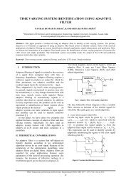
with hub in Pro-e s<strong>of</strong>tware. The Assembly <strong>of</strong><br />
components <strong>of</strong> the <strong>Kaplan</strong> turbine are shown figure 1.<br />
Figure 1. Assembly <strong>of</strong> <strong>Kaplan</strong> turbine<br />
Meshing <strong>of</strong> components was carried out in mesh<br />
module in ANASY-14 s<strong>of</strong>tware. The mesh data <strong>of</strong><br />
different components <strong>of</strong> the turbine is shown in Table I<br />
and the mesh models <strong>of</strong> the turbine are as given in figure<br />
2, 3 & 4.<br />
Component<br />
Table I. Summery <strong>of</strong> mesh data<br />
Tubular casing 754929<br />
No. <strong>of</strong> Element<br />
Wicket gate 1523396<br />
Runner 486116<br />
Figure 2. Meshed model <strong>of</strong> tubular casing with draft tube<br />
The numerical analysis <strong>of</strong> turbine performance and<br />
internal flow were carried out with the help <strong>of</strong> Fluent<br />
module <strong>of</strong> ANSYS-14. Standard k-ε turbulence model<br />
for single phase was used for the numerical simulation.<br />
International Conference on Mechanical and Industrial Engineering<br />
10
<strong>CFD</strong> <strong>Based</strong> <strong>Performance</strong> <strong>Analysis</strong> <strong>of</strong> <strong>Kaplan</strong> <strong>Turbine</strong> for Micro Hydro Power<br />
The simulations were carried out for design condition<br />
and part load conditions with wicket gate openings at<br />
75%, 65% and 55%. For each wicket gate opening four<br />
simulations were carried out by varying runner blade<br />
angle to optimize the efficiency. For Set <strong>of</strong> boundary<br />
conditions mass flow rate was specified at casing inlet<br />
and pressure outlet was specified at draft tube outlet.<br />
Grid interface was defined between casing and runner as<br />
well as between runner and wicket gate.<br />
Figure 3. Meshed model <strong>of</strong> Wicket gate<br />
The input parameters for calculating efficiency are as<br />
given below;<br />
a. Total pressure at turbine outlet(P t2 )<br />
b. Discharge through turbine(Q)<br />
c. the angular speed <strong>of</strong> the runner (ω)<br />
The output parameters for calculating the efficiency are<br />
shown below;<br />
a. Total pressure at turbine inlet(P t1 )<br />
b. The net torque acting on the runner(T)<br />
3.1 Efficinecy for design condition<br />
Simulation was carried out <strong>of</strong> the <strong>Kaplan</strong> turbine with<br />
design parameters, which are the discharge is 7.03 m 3 /s<br />
and head 1.5 m. For design condition wicket gate<br />
opening is taken 85% i.e. 7.03 m 3 /s and the runner blade<br />
angle is equal to the 18° at the outer distortion.<br />
1. Input Parameters: The input parameters for the Fluent<br />
are as given in Table II<br />
Table II. Input parameter for fluent<br />
Discharge, Q (m 3 /s)<br />
Angular speed, ω<br />
(rad/s)<br />
Pressure at outlet<br />
<strong>of</strong> <strong>Turbine</strong>, P t2 (Pa)<br />
7.03 13.09 15092<br />
Figure 4. Meshed model <strong>of</strong> <strong>Kaplan</strong> Runner<br />
3. RESULT AND DISCUSSION<br />
3.1 Computation efficiency <strong>of</strong> hydro turbine<br />
The overall efficiency <strong>of</strong> a turbine with an<br />
incompressible working fluid is defined as the ratio <strong>of</strong><br />
the work delivered to the rotor to the energy available<br />
from the fluid stream. This ratio can be expressed as:<br />
T ω<br />
η<br />
0<br />
=<br />
(1)<br />
Q ( P t 1<br />
− P t 2<br />
)<br />
Where, T is the net torque acting on the runner (N-m), ω<br />
is the angular speed (radian), Q is discharge through<br />
turbine (m3/s), P t1 is total pressure at the inlet to the<br />
turbine and P t2 is the total pressure at the exit <strong>of</strong> the draft<br />
tube.<br />
2. Output Parameters: The output parameters generated<br />
by the Fluent are as given in Table III<br />
Pressure at inlet<br />
<strong>of</strong> turbine, P t1<br />
(Pa)<br />
Table III. .Output parameter<br />
Tx<br />
(N-m)<br />
136710.5 -33.38<br />
Torque components<br />
Ty<br />
(N-m)<br />
-<br />
114.67<br />
Tz<br />
(N-m)<br />
Torque, T<br />
(N-m)<br />
-59487.15 59487.27<br />
The efficiency <strong>of</strong> the <strong>Kaplan</strong> turbine for design condition<br />
has been found to be 91% from the Equation (1).<br />
3.2 Pressure contour for design condtion.<br />
The pressure variations obtained through the numerical<br />
simulation are shown in the form <strong>of</strong> pressure contours.<br />
The Pressure contours <strong>of</strong> turbine components are shown<br />
in the figure 5. The total pressure variation is high near<br />
the wall <strong>of</strong> the casing and runner. It is observed through<br />
analysis that at inlet <strong>of</strong> the casing is maximum pressure.<br />
International Conference on Mechanical and Industrial Engineering<br />
11
<strong>CFD</strong> <strong>Based</strong> <strong>Performance</strong> <strong>Analysis</strong> <strong>of</strong> <strong>Kaplan</strong> <strong>Turbine</strong> for Micro Hydro Power<br />
gate opening increases as increasing the runner blade<br />
angle and have maximum efficiency 85.38% at 20°<br />
runner blade angle. The variation <strong>of</strong> efficiency with<br />
runner blade for 65% opening is shown in figure 7.<br />
Runner<br />
Wicket gate<br />
Efficiency<br />
86<br />
85<br />
84<br />
83<br />
82<br />
81<br />
80<br />
79<br />
17 18 19 20 21 22<br />
Runner Blade Angle<br />
Figure 7. Variation <strong>of</strong> efficiency with runner blade angle<br />
Tubular casing with daft tube<br />
Figure 5. Contours <strong>of</strong> components <strong>of</strong> <strong>Kaplan</strong> turbine for<br />
design condition<br />
3.3 Efficiency at 75% wicket gate opening<br />
Four different runner blade angles17°, 18°, 19° and 20°<br />
has been used for four simulation <strong>of</strong> the <strong>Kaplan</strong> at 75%<br />
<strong>of</strong> wicket gate opening. The efficiency for 75% wicket<br />
gate opening increases as increasing the runner blade<br />
angle and have maximum efficiency 90.41% at 19°<br />
runner blade angle. The variation <strong>of</strong> efficiency with<br />
runner blade is shown in figure 6.<br />
Efficiency<br />
91<br />
90<br />
89<br />
88<br />
87<br />
86<br />
85<br />
84<br />
16 17 18 19 20 21<br />
Runner Blade angle<br />
Figure 6. Variation <strong>of</strong> efficiency with runner blade angle<br />
3.4 Efficiency at 65% wicket gate opening<br />
Four different runner blade angles18°, 19°, 20° and 21°<br />
has been used for four simulation <strong>of</strong> the <strong>Kaplan</strong> at 65%<br />
<strong>of</strong> wicket gate opening. The efficiency for 65% wicket<br />
3.5 Efficiency at 55% wicket gate opening<br />
Four different runner blade angles19°, 20°, 21° and 22°<br />
has been used for four simulation <strong>of</strong> the <strong>Kaplan</strong> at 55%<br />
<strong>of</strong> wicket gate opening. The efficiency for 55% wicket<br />
gate opening increases as increasing the runner blade<br />
angle and have maximum efficiency 76.35% at 21°<br />
runner blade angle. The variation <strong>of</strong> efficiency with<br />
runner blade is shown in figure 8.<br />
Efficiency<br />
77<br />
76<br />
75<br />
74<br />
73<br />
72<br />
71<br />
70<br />
18 19 20 21 22 23<br />
Runner Blade Angle<br />
Figure 8. Variation <strong>of</strong> efficiency with runner blade angle<br />
3.6 Efficiency curve for different operating conditions<br />
The graph between efficiency and runner blade angle are<br />
show in figure 9. The figure shows different wicket gate<br />
opening curves which is shown by different colors. The<br />
efficiency curve plot by joining efficiency <strong>of</strong> design<br />
condition and the peak efficiencies <strong>of</strong> all part load<br />
conditions.<br />
International Conference on Mechanical and Industrial Engineering<br />
12
<strong>CFD</strong> <strong>Based</strong> <strong>Performance</strong> <strong>Analysis</strong> <strong>of</strong> <strong>Kaplan</strong> <strong>Turbine</strong> for Micro Hydro Power<br />
Efficiency<br />
93<br />
91<br />
89<br />
87<br />
85<br />
83<br />
81<br />
79<br />
77<br />
75<br />
73<br />
71<br />
69<br />
67<br />
65<br />
16 17 18 19 20 21 22 23<br />
Runner Blade angle<br />
75% wicket gate opening<br />
65% wicket gate opening<br />
55% wicket gate opening<br />
Part load efficiency curve<br />
Figure 9.<br />
Efficiency curve for different part load condition<br />
4. CONCLUSION<br />
In the present study, the operating parameters <strong>of</strong> the<br />
<strong>Kaplan</strong> turbine have been optimized using commercial<br />
<strong>CFD</strong> package ANSYS-14. The turbine having rated<br />
capacity <strong>of</strong> 100 kW at rated head and discharge <strong>of</strong> 1.5 m<br />
and 7.03 m3/s respectively. The simulation has been<br />
carried out for three-dimensional with k- ε turbulence<br />
model. <strong>Based</strong> on <strong>CFD</strong> analysis it has been found the total<br />
pressure variation is high in runner and the wall <strong>of</strong> the<br />
casing. In the casing inlet maximum value <strong>of</strong> total<br />
pressure has been observed while minimum value <strong>of</strong><br />
pressure variation occurs at wicket gates as compare to<br />
other components. The efficiency <strong>of</strong> the <strong>Kaplan</strong> tubular<br />
turbine has been found to be maximum as 91% for design<br />
condition i.e. at rated discharge 7.03m3/s and at rated<br />
head 1.5 m at 85% wicket gate opening.<br />
[2]. Drtina, P and Sallaberger, M “Hydraulic<br />
turbines—basic principles and state-<strong>of</strong>-theart<br />
computational fluid dynamics applications” Proc<br />
Instn Mech Engrs Vol 213 Part C 1999<br />
[3]. Prasad, V, Gahlot, V K & Krinnamachar, P “<strong>CFD</strong><br />
approach for design optimization and validation<br />
for axial flow hydraulic turbine” Indian Journal <strong>of</strong><br />
Engineering & Material secince Vol. 16, August<br />
2009,pp 229-236<br />
[4]. Jain, S, Saini,R P & Kumar, A “<strong>CFD</strong> approach for<br />
prediction <strong>of</strong> efficiency <strong>of</strong> Francis turbine”<br />
IGHEM-2010, oct. 21-23, AHEC, IIT Roorkee,<br />
India<br />
[5]. Kim, Y T, Nam, S H, Cho, Y J, Hwang, Y, C,<br />
Choi,Y D, Nam, C D & Lee, Y H “Tubular-Type<br />
hydro turbine performance for variable guide vane<br />
opening by <strong>CFD</strong>” The fifth international<br />
conference on fluid mechanics, Aug 15-19,2007,<br />
Shanghai, Chaina.<br />
REFERENCES<br />
[1]. Yukse, I “As a renewable energy hydropower for<br />
sustainable development in Turkey” Renewable<br />
and Sustainable Energy Reviews 14 (2010) 3213–<br />
3219<br />
International Conference on Mechanical and Industrial Engineering<br />
13