Optical Glass Metrology â Techniques / Limitations - Owens Design
Optical Glass Metrology â Techniques / Limitations - Owens Design
Optical Glass Metrology â Techniques / Limitations - Owens Design

Create successful ePaper yourself
Turn your PDF publications into a flip-book with our unique Google optimized e-Paper software.
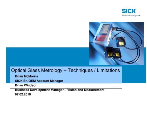
<strong>Optical</strong> <strong>Glass</strong> <strong>Metrology</strong> – <strong>Techniques</strong> / <strong>Limitations</strong><br />
Brian McMorris<br />
SICK Sr. OEM Account Manager<br />
Brian Windsor<br />
Business Development Manager – Vision and Measurement<br />
07.02.2010
“<strong>Optical</strong>” Energy Spectrum<br />
: SICK AG: : BU02 side session: high end displacement Patrick Nutz 19.03.2009 2
<strong>Limitations</strong> of <strong>Optical</strong> Measurement <strong>Techniques</strong><br />
: Contrast<br />
- Differential intensity in measured light is improved by optical contrast (due to color or reflectivity);<br />
: Light Spectrum (Reflection / Absorption)<br />
- Light must be reflected by object to be measured; Absorption of light by object can be overcome<br />
by changes in light source / wavelength<br />
: Wavelength<br />
- Direct distance measurement is limited by the resolution of the measuring instrument or<br />
reference source; but interpolation is possible at less than one wavelength through interference<br />
techniques<br />
- Visible light has a wavelength of 380nm (Blue) to 750nm (Red); therefore optical techniques are<br />
limited to resolution of about 0.5 micron in the visible spectrum<br />
: Ambient Light “Noise”<br />
- Measured light must differ in intensity from ambient light sources; signal-to-noise ratio should<br />
exceed 10:1<br />
- Selecting frequency / wavelength of light different than highest intensity ambient wavelengths<br />
(probably in visible red spectrum) can also improve signal-to-noise ratio in the specific frequency<br />
measured<br />
: <strong>Optical</strong> Distortion<br />
- Due primarily to lens quality limitations; atmospheric limitations such as air contaminants<br />
: SICK AG: : BU02 side session: high end displacement<br />
Patrick Nutz 19.03.2009 3
Overview of <strong>Optical</strong> <strong>Glass</strong> Measurement<br />
<strong>Techniques</strong> (aka “Microscopy”)<br />
: Laser Triangulation<br />
: Illumination and Contrast Methods<br />
- Confocal<br />
- AutoFocus<br />
- Bright Field Microscopy<br />
- Dark Field Microscopy<br />
- Kohler Illumination<br />
- Phase Contrast<br />
: Fluorescence Methods<br />
- Two Photon Excitation Microscopy<br />
- Multiphoton Excitation<br />
- Deconvolution<br />
: Sub-Diffraction Limit<br />
- Structured Illumination (Vertico SMI)<br />
- Near-Field<br />
: SICK AG: : BU02 side session: high end displacement<br />
Patrick Nutz 19.03.2009 4
Laser Triangulation<br />
Advantages<br />
: Simplicity of Technique<br />
: Non-Ambiguous Measurement<br />
: Low Cost of Execution<br />
: Lends Itself to Inline Analysis<br />
: Flexibility (light sources / lensing)<br />
: Scalability<br />
Disadvantages<br />
: <strong>Limitations</strong> on Resolution<br />
: <strong>Optical</strong> Occlusion<br />
: SICK AG: : BU02 side session: high end displacement<br />
Patrick Nutz 19.03.2009 5
Detection of the <strong>Glass</strong> Plate Interface<br />
- general Principle -<br />
d 1 t 1 t 2 t 3 t 4<br />
t 5<br />
: Light Distribution on the receiver element<br />
: SICK AG: : BU02 side session: high end displacement : Name (Date) 6
Detection of the <strong>Glass</strong> Plates Interface<br />
- material tilting tolerance<br />
: SICK AG: : BU02 side session: high end displacement : Name (Date) 7
Detection of the <strong>Glass</strong> Plate Interface<br />
- material tilting tolerance<br />
: SICK AG: : BU02 side session: high end displacement : Name (Date) 8
<strong>Glass</strong> Thickness Measurement<br />
with one OD-Precision Sensorhead<br />
Photos of the light distribution Monitor: <strong>Glass</strong>plate with distance to the background :<br />
OK<br />
•Sharp two Peaks of the<br />
glassplate visible<br />
•Third peak of the background<br />
visible<br />
•Two red lines to measure the<br />
distance inbetween (first two<br />
from the left)<br />
•Peaks clearly over the blue<br />
threshold line<br />
NOK<br />
•Sharp two Peaks of the glassplate visible<br />
•Third peak of the background visible<br />
•Only one red line of the backside edge of<br />
the glassNo thickness measurement<br />
possible because first edge is out of range<br />
•Peaks clearly over the blue threshold line<br />
: SICK AG: : BU02 side session: high end displacement : Name (Date) 9
<strong>Optical</strong> Time-of-Flight Technique<br />
Principle:<br />
Laser light source generates a pulse which travels to object and is reflected back to receiver. Time<br />
from emission to reception is measured at high speed. Range is a function of ½ the time divided<br />
by the time constant (299,792,458 m/s). Ambiguity interval can be eliminated by phase<br />
modulation. Also called Time Domain Reflectometry (TDR) and LIDAR (when executed in a<br />
scanning technique like the electro-magnetic equivalent RADAR)<br />
Advantages:<br />
- Simplicity of concept<br />
- Low Cost Solution for Moderate Resolution Features<br />
- High signal to noise ratio (ambient light noise)<br />
- Measurement of high aspect-ratio holes<br />
- Measurement from low to high reflectivity<br />
- Measurement of transparent objects<br />
<strong>Limitations</strong>:<br />
- Speed –of-light constant<br />
- Detection speed and response time over short distances (1 micron = 6.0 x 10 -14 seconds)<br />
- Mechanical Scanning for Single Point<br />
- X-Y Resolution for Arrayed Sensor<br />
: SICK AG: : BU02 side session: high end displacement<br />
Patrick Nutz 19.03.2009 10
LaserScanner with<br />
rotating Mirror<br />
Detection and<br />
Measurement of Object<br />
Distance and Size<br />
Example of Occlusion<br />
: SICK AG: : BU02 side session: high end displacement Patrick Nutz 19.03.2009 11
Confocal<br />
: Confocal microscopy generates the image in a completely<br />
different way to normal "wide-field" microscopes.<br />
: Using a scanning point of light instead of full sample<br />
illumination confocal microscopy gives slightly higher<br />
resolution, and significant improvements in optical sectioning<br />
by blocking the influence of out-of-focus light which would<br />
otherwise degrade the image<br />
: Single point measurement in “Z” axis, so instrument or object<br />
must be moved in X and Y to generate 3D image<br />
: SICK AG: : BU02 side session: high end displacement<br />
Patrick Nutz 19.03.2009 12
Confocal Laser Point Sensor<br />
: SICK AG: : BU02 side session: high end displacement Patrick Nutz 19.03.2009 13
Confocal Laser Point Sensor<br />
Principle:<br />
: The confocal point sensor uses a point light source and detector pinhole to discriminate depth<br />
: The laser beam emitted from the point light source is focused on a specimen through an objective<br />
lens that moves rapidly up and down. The maximum light intensity occurs when the specimen lies<br />
within the focal plane of the objective. As the objective moves closer to or farther from the<br />
specimen, however, the reflected light reaching the pinhole is defocused and does not pass<br />
through it. As a result, the quantity of light received by a detector behind the pinhole decreases<br />
rapidly. A detection signal is only generated when the maximum of light goes through the pinhole.<br />
: A precise height measurement of the illuminated point is achieved by continuously scanning along<br />
the z-axis.<br />
Advantages:<br />
- Vibration-free measurement<br />
- Exceptional sub-nanometric resolution<br />
- High signal to noise ratio<br />
- Thin layer thickness measurement<br />
(min. measurable thickness: ~ 0.4 µm)<br />
- Measurement of high aspect-ratio holes<br />
- Measurement from low to high reflectivity<br />
- Measurement of transparent objects<br />
: SICK AG: : BU02 side session: high end displacement<br />
Patrick Nutz 19.03.2009 14
Chromatic Confocal Measurement<br />
: SICK AG: : BU02 side session: high end displacement Patrick Nutz 19.03.2009 15
Chromatic Confocal Measurement<br />
Principle:<br />
: A chromatic lens L generates the image of a point white-light source W as a continuum of monochromatic images<br />
located on the optical axis (“Chromatic coding”). A sample is located inside the color-coded segment and its<br />
surface scatters the incident light beam.<br />
: The backscattered light passes through the chromatic lens L in the opposite direction, and arrives at a pinhole P<br />
which filters out all wavelengths except a single wavelength, M . The collected light is analyzed by a spectrometer<br />
S. The sample position (point M) is directly related to the detected wavelength.<br />
Advantages:<br />
- High resolution<br />
- High signal-to-noise ratio<br />
- No motion in “Z” required<br />
- Works on all types of samples<br />
- Wide choice of measuring ranges<br />
- Steep slope compatibility<br />
- Coaxial (no shadowing)<br />
- “Speckle” free from low to high reflectivity<br />
- Measurement of transparent objects<br />
: SICK AG: : BU02 side session: high end displacement<br />
Patrick Nutz 19.03.2009 16
Principle of operation of an AutoFocus sensor<br />
The light source is projected by the object lens on the sample's surface.<br />
- The reflected light is collected by the very same lens, focused by the collimator lens<br />
and deflected towards the detector by a beam splitter.<br />
- In the absence of the cylindrical lens, the light would converge to a tiny spot on the<br />
detector.<br />
- The cylindrical lens deviates only one axis of the light, so a horizontal and a vertical<br />
focal line originate from the single spot.<br />
The detector is placed mid-way between the two focal lines.<br />
- A circular spot appears on the sensor if the surface is exactly in-focus.<br />
- Deviation from the focal position results in an elliptic spot on the detector.<br />
- The orientation and eccentricity of the spot depends on the magnitude and direction<br />
of the defocus.<br />
The spot's shape is detectable by the current distribution in a photodiode<br />
array.<br />
- The sensor's electronics generate an error signal resulting in a movement of the<br />
object lens to track the surface at exactly the focal distance. The motion of the lens<br />
is monitored by an incremental encoder (glass scale), comprising the profile signal.<br />
: SICK AG: : BU02 side session: high end displacement<br />
Patrick Nutz 19.03.2009 17
Example of AutoFocus Execution<br />
A precise digital position measurement system<br />
enables high resolution down to 25 nm<br />
: SICK AG: : BU02 side session: high end displacement Patrick Nutz 19.03.2009 18
: Thank you for your attention.