Compumotor Step Motor & Servo Motor Systems and Controls
Compumotor Step Motor & Servo Motor Systems and Controls
Compumotor Step Motor & Servo Motor Systems and Controls

You also want an ePaper? Increase the reach of your titles
YUMPU automatically turns print PDFs into web optimized ePapers that Google loves.
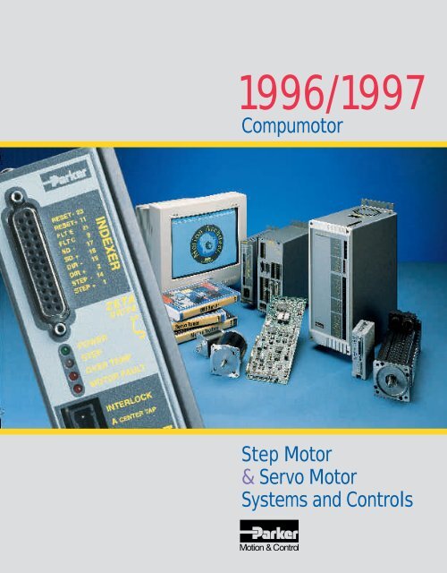
1996/1997<br />
<strong>Compumotor</strong><br />
<strong>Step</strong> <strong>Motor</strong><br />
& <strong>Servo</strong> <strong>Motor</strong><br />
<strong>Systems</strong> <strong>and</strong> <strong>Controls</strong>
STEPMOTOR&<br />
SERVOMOTOR<br />
SYSTEMSAND<br />
CONTROLSSTE<br />
PMOTOR&SERV<br />
OMOTORSYST<br />
EMSANDCON<br />
TROLSSTEPM<br />
OTOR&SERVOM<br />
OTORSYSTEM<br />
SANDCONTRO<br />
COMPUMOTOR<br />
THE COMPLETE SOURCE FOR<br />
PROGRAMMABLE MOTION CONTROL<br />
A Broad Range of Capabilities<br />
If you have a motion control problem,<br />
turn to <strong>Compumotor</strong>. We offer<br />
a comprehensive line-up of product<br />
technologies, plus we provide the<br />
technical support to ensure timely,<br />
expert assistance in product selection,<br />
installation, programming,<br />
training <strong>and</strong> troubleshooting. From<br />
h<strong>and</strong>s-on technical seminars to<br />
local Automation Technology Centers<br />
to factory-trained field application<br />
engineers—solutions to your<br />
motion control problems are only a<br />
phone call away.<br />
A Basis to Objectively Recommend<br />
the Best Solution<br />
A full spectrum of motion control<br />
technologies allows us to objectively<br />
recommend the best solution<br />
to your specific problem. We offer:<br />
• <strong>Step</strong>per motor <strong>and</strong> servo systems<br />
• Half/full step <strong>and</strong> microstepping<br />
• Digital <strong>and</strong> analog drives<br />
• Open loop <strong>and</strong> closed loop systems<br />
• Brushed <strong>and</strong> brushless motor/drives<br />
• Position, velocity <strong>and</strong> torque control<br />
servos<br />
• St<strong>and</strong> alone <strong>and</strong> peripheral controls<br />
• Absolute <strong>and</strong> incremental feedback<br />
• Encoder <strong>and</strong> resolver feedback<br />
servos<br />
• Direct drive rotary motors <strong>and</strong> motors<br />
attached to gearboxes, tables, etc.<br />
• Linear motors <strong>and</strong> motors mounted<br />
to leadscrews, belt drives, etc.<br />
So, if you’re looking for the final<br />
word on motion control, turn to the<br />
company that has all the possibilities—<br />
<strong>Compumotor</strong>.
P<br />
A POWERFUL LINE-UP OF PROGRAMMABLE CONTROLS<br />
Engineering Reference<br />
<strong>and</strong> Application<br />
Solutions<br />
<strong>Step</strong> <strong>Motor</strong> <strong>Systems</strong><br />
<strong>Compumotor</strong> provides<br />
thorough technical data <strong>and</strong><br />
support for every product. In<br />
Section A, you’ll find motor<br />
<strong>and</strong> drive technology<br />
definitions, how-to application<br />
information, formulas, <strong>and</strong><br />
application examples. A<br />
special <strong>Motor</strong> Sizing <strong>and</strong><br />
Selection Software disk<br />
compliments this catalog <strong>and</strong><br />
is available to help you<br />
determine the optimum motor<br />
for your application. And if you<br />
have any other questions<br />
about products or services,<br />
call your local, factory-trained<br />
applications engineer or our<br />
Applications Engineering<br />
department at our toll-free<br />
factory line: 1-800-358-9070.<br />
<strong>Servo</strong> <strong>Systems</strong><br />
<strong>Compumotor</strong>’s servo systems<br />
offer power <strong>and</strong> diversity in a<br />
multitude of form factors.<br />
<strong>Compumotor</strong> offers a wide<br />
range of digital <strong>and</strong> analog<br />
servo drives for all your motion<br />
needs, as well as convenient<br />
packaged servo systems.<br />
<strong>Compumotor</strong>’s powerful servo<br />
controllers operate st<strong>and</strong>alone<br />
or in an AT-bus structure<br />
<strong>and</strong> are easily interfaced to<br />
PLCs, PCs or other factory<br />
equipment.<br />
B1-B146<br />
<strong>Compumotor</strong> pioneered<br />
microstepping techniques to<br />
electronically improve the<br />
smoothness <strong>and</strong> resolution of<br />
step motors. The leadership<br />
continues with a complete<br />
range of products, from full<br />
step <strong>and</strong> microstepping<br />
systems to packaged single<strong>and</strong><br />
multi-axis drive/indexer<br />
systems <strong>and</strong> powerful single<strong>and</strong><br />
multi-axis indexers.<br />
C1-C160<br />
An Introduction to<br />
<strong>Compumotor</strong><br />
Page<br />
Worldwide Support .......... 2-3<br />
Technical Support Team .. 4-5<br />
Seminars ......................... 6-7<br />
Support Software ............ 8-9<br />
<strong>Servo</strong> vs. <strong>Step</strong>per<br />
<strong>Motor</strong> Selection ........... 10-11<br />
<strong>Servo</strong> <strong>Systems</strong> ............ 12-13<br />
<strong>Step</strong>per <strong>Systems</strong> ......... 14-15<br />
Custom Products .............. 16<br />
A1-A96<br />
O<br />
T<br />
O<br />
R<br />
M<br />
U<br />
M<br />
O<br />
C<br />
1
INNOVATIVE SOLUTIONS AND UNRIVALLED SUPPORT<br />
The Foundation for<br />
Continued Leadership<br />
Manufacturing<br />
Workcells<br />
Our corporate mission is to<br />
become the leading supplier of<br />
electronic motion control<br />
equipment worldwide.<br />
<strong>Compumotor</strong>’s merger in May<br />
1986, with Parker Hannifin<br />
Corporation has helped<br />
provide the technical <strong>and</strong><br />
financial resources necessary<br />
to fulfill that role. With a 70-<br />
year history of successfully<br />
supplying motion control<br />
components <strong>and</strong> systems,<br />
Parker Hannifin enhances<br />
<strong>Compumotor</strong>’s foundation for<br />
continued leadership.<br />
Our Strategy for Your<br />
Success<br />
Our strategy for success is<br />
simple: provide our customers<br />
with a competitive advantage.<br />
We do so by offering<br />
continuous product<br />
innovation, complete<br />
solutions, <strong>and</strong> unrivalled<br />
technical support.<br />
Our manufacturing workforce<br />
consists of efficient workcells,<br />
all dedicated to producing a<br />
product family. Each workcell<br />
member has a voice in<br />
streamlining every<br />
manufacturing process. The<br />
workcell includes a member<br />
from our Marketing,<br />
Applications Engineering,<br />
Customer Service, <strong>and</strong><br />
Manufacturing departments—<br />
customer feedback <strong>and</strong><br />
special requests can be<br />
discussed with those actually<br />
making your product. This<br />
level of communication gives<br />
us the flexibility to alter<br />
manufacturing steps to furnish<br />
you with the exact product<br />
you want. Our manufacturing<br />
workforce is completely crosstrained<br />
to work on several<br />
different workcells. Crosstraining<br />
is yet another method<br />
we use to efficiently respond<br />
to your order <strong>and</strong> overall<br />
product dem<strong>and</strong>.<br />
Internal Manufacturing<br />
Parker Hannifin has invested in<br />
state-of-the-art surface mount<br />
<strong>and</strong> automated insertion<br />
machines to guarantee a<br />
prompt response to orders.<br />
Unlike many other companies,<br />
Parker Hannifin has the<br />
flexibility to build any product<br />
in any quantity (based on<br />
dem<strong>and</strong>) without relying on an<br />
outside turn-key vendor to<br />
build our boards. If your<br />
manufacturing growth requires<br />
more Parker Hannifin product,<br />
we can grow with you! Our<br />
manufacturing philosophy is<br />
simple:<br />
• Authorize JIT-based vendors<br />
to provide raw materials<br />
with low lead times<br />
• Reduce our dock-to-stock<br />
time required to receive the<br />
raw parts before we can<br />
build products<br />
• Build all boards internally<br />
with state-of-the-art surface<br />
mount <strong>and</strong> PCA equipment<br />
• Provide consistent lead<br />
times to our customers<br />
regardless of product mix<br />
2
COMPUMOTOR<br />
Quality Products<br />
At Parker Hannifin, producing<br />
quality products is our number<br />
one priority. Our products are<br />
designed with high quality<br />
st<strong>and</strong>ards <strong>and</strong> are<br />
manufactured with state-ofthe-art<br />
equipment <strong>and</strong><br />
production methods. Before<br />
any product reaches our<br />
customers, it must pass a<br />
rigorous set of hardware <strong>and</strong><br />
software tests. JIT (Just-intime)<br />
manufacturing <strong>and</strong> DFM<br />
(Design-for-Manufacturability)<br />
methods lend themselves to<br />
creating the necessary<br />
flexibility to readily<br />
accommodate your special<br />
needs. As an example of these<br />
manufacturing principles in<br />
action, many of our products<br />
have earned UL recognition.<br />
In addition to adhering to our<br />
own rigorous st<strong>and</strong>ards,<br />
Parker Hannifin is dedicated to<br />
meeting existing quality<br />
requirements established by<br />
the industry. The ISO-9000<br />
international quality st<strong>and</strong>ard<br />
involves a supplier’s internal<br />
production processes <strong>and</strong><br />
services. ISO-9000 is a<br />
st<strong>and</strong>ard credential that<br />
verifies that a supplier has a<br />
quality process in place. Due<br />
to the emphasis of ISO-9000<br />
in Europe, Parker Hannifin has<br />
already achieved the ISO-<br />
9000 st<strong>and</strong>ard at its Digiplan<br />
division. Many of the quality<br />
practices performed at<br />
Digiplan have been adopted at<br />
the <strong>Compumotor</strong> division.<br />
Two-Year Warranty<br />
It’s one thing to promise<br />
reliability, quality <strong>and</strong> service;<br />
<strong>and</strong> quite another to<br />
guarantee it—especially in a<br />
global marketplace. That’s<br />
why we offer a two-year<br />
warranty on our entire line of<br />
motors, drives, encoders, <strong>and</strong><br />
controllers.<br />
U<br />
T<br />
I<br />
O<br />
L<br />
O<br />
N<br />
S<br />
S<br />
3
TOTAL SUPPORT FROM CONCEPT TO IMPLEMENTATION<br />
Local Product<br />
Availability<br />
<strong>and</strong> Service—<br />
Around the World<br />
At Parker Hannifin, we<br />
underst<strong>and</strong> the dem<strong>and</strong>s of<br />
the global marketplace.<br />
Throughout North America,<br />
Europe <strong>and</strong> the Pacific Rim,<br />
our motion control products<br />
are delivered <strong>and</strong> supported<br />
through a comprehensive<br />
network of Automation<br />
Technology Centers (ATCs).<br />
ATCs serve the industrial<br />
needs unique to each region.<br />
Parker Hannifin’s<br />
Electromechanical<br />
Territory Manager<br />
Everyone promises service,<br />
but <strong>Compumotor</strong> has the<br />
people to assure timely, expert<br />
support. For example, Parker<br />
Hannifin employs a competent<br />
<strong>and</strong> motivated team of<br />
degreed, factory-trained field<br />
application engineers who are<br />
ready to offer you assistance<br />
in product selection,<br />
installation, product/system<br />
programming <strong>and</strong><br />
troubleshooting.<br />
Authorized Automation<br />
Technology Centers<br />
Your local independent<br />
Automation Technology Center<br />
has been factory-trained to<br />
offer you expert service <strong>and</strong><br />
advice. The network includes<br />
90 organizations <strong>and</strong> more<br />
than 125 outlets throughout<br />
the world. In addition to those<br />
services offered by traditional<br />
distributors, these<br />
organizations specialize in the<br />
application of high technology<br />
automation equipment. Parker<br />
Hannifin works cooperatively<br />
with its authorized ATCs to<br />
recruit, hire, <strong>and</strong> train degreed<br />
engineers for positions with<br />
ATC organizations. ATCs offer<br />
local product availability,<br />
product demonstrations,<br />
complementary products <strong>and</strong><br />
services, programming<br />
assistance, system integration,<br />
<strong>and</strong> in-depth customer<br />
seminars.<br />
Engineering Support<br />
Tools to Make Your Job<br />
Easier<br />
Years of experience have<br />
culminated in a vast<br />
assortment of engineering<br />
support tools that help to<br />
simplify the sizing, selection,<br />
<strong>and</strong> installation process,<br />
design a system to custom<br />
application requirements, <strong>and</strong><br />
troubleshoot existing<br />
installations. A few of these<br />
tools include:<br />
• <strong>Motor</strong> Sizing <strong>and</strong> Selection<br />
Software<br />
• Application Programming<br />
Software<br />
• Application success stories<br />
• Product installation videos<br />
• In-depth h<strong>and</strong>books on<br />
subjects such as feed-tolength<br />
• The consolidated<br />
engineering reference,<br />
Section A of this catalog<br />
• A customer newsletter<br />
4
ASSISTANCE AT YOUR FINGERTIPS<br />
1-800 Applications<br />
Engineering Assistance<br />
When you have urgent<br />
questions, expert answers are<br />
only a phone call away. A<br />
team of engineers is ready to<br />
take your call from 6:00 a.m.<br />
to 5:00 p.m. PST. These<br />
engineers have practical field<br />
experience <strong>and</strong> are prepared<br />
to provide you with application<br />
<strong>and</strong> product assistance<br />
throughout the stages of your<br />
project <strong>and</strong> for the life of the<br />
product. Just call 1-800-358-<br />
9070. Outside the U.S. call<br />
707-584-7558.<br />
E-Mail<br />
In addition to the 1-800<br />
number, you can call<br />
<strong>Compumotor</strong> via the Internet.<br />
Designed as a question <strong>and</strong><br />
answer forum, leave us<br />
messages, requests for<br />
literature, or send <strong>and</strong> retrieve<br />
files. <strong>Compumotor</strong>’s E-mail<br />
system is available 24 hours a<br />
day, 7 days a week. To reach<br />
our system simply punch in:<br />
tech_help@cmotor.com<br />
Fax<br />
Bulletin Board<br />
Use your modem to access a<br />
wide variety of sample<br />
programs, CAD drawings,<br />
support software, <strong>and</strong> even a<br />
message interface. To reach<br />
<strong>Compumotor</strong>’s Bulletin Board,<br />
dial 707-584-4059.<br />
S<br />
U<br />
P<br />
P<br />
O<br />
<strong>Compumotor</strong> offers a fax<br />
service to customers to<br />
answer questions <strong>and</strong> review<br />
short programs. Answers will<br />
be faxed or phoned back<br />
within 24 hours. To send us a<br />
fax dial 707-584-3793.<br />
R<br />
T<br />
5
S<br />
SEMINARS: PROVIDING THE TOOLS TO MAKE INFORMED DECISIONS<br />
Motion Control<br />
Technology Training at<br />
<strong>Compumotor</strong><br />
Customers can attend training<br />
courses at <strong>Compumotor</strong>.<br />
Training courses are available<br />
on a variety of technical topics<br />
as well as product-specific<br />
instruction. The courses are<br />
designed to give attendees<br />
h<strong>and</strong>s-on, practical training<br />
with experienced engineers. In<br />
many cases, the actual<br />
product design engineers will<br />
conduct the training. This<br />
program provides our<br />
customers with a unique<br />
opportunity to develop a<br />
better underst<strong>and</strong>ing of<br />
application design,<br />
development, <strong>and</strong><br />
programming. Participants will<br />
also develop a better<br />
underst<strong>and</strong>ing of Parker<br />
Hannifin <strong>and</strong> its commitment<br />
to quality products <strong>and</strong><br />
service.<br />
N<br />
A<br />
Local <strong>and</strong> In-House<br />
Presentations Bring the<br />
Leading Edge to You<br />
<strong>Compumotor</strong> assures you<br />
have access to the latest<br />
information by conducting<br />
over 100 local seminars <strong>and</strong><br />
product workshops annually. If<br />
you need an in-house<br />
presentation, talk to your<br />
Automation Technology Center<br />
or field application engineer.<br />
We can customize programs<br />
to your specific requirements.<br />
R<br />
S<br />
I<br />
M<br />
E<br />
More Factory Training<br />
for Customers<br />
6
PROBLEM SOLVING WORKSHOPS & SEMINARS TO ADDRESS YOUR NEEDS<br />
Come With a Problem,<br />
Leave With a Solution<br />
Since 1986, our Automation<br />
Technology Centers have<br />
conducted motion control<br />
seminars for over 11,000<br />
attendees. At our seminars,<br />
you’ll be briefed not only on<br />
the basics of programmable<br />
motion control, but also on the<br />
newest, most innovative<br />
technologies in the industry—<br />
<strong>and</strong> given the facts to evaluate<br />
them for your applications.<br />
Seminars are more than<br />
informational programs—<br />
they’re problem-solving<br />
sessions that address your<br />
needs. So bring a motion<br />
control problem. You can<br />
expect to leave with a Parker<br />
Hannifin solution.<br />
You’ll Take Away More<br />
Than Ideas<br />
Attendees to our seminars get<br />
more than answers. They<br />
receive presentation materials,<br />
article reprints, support<br />
software, assignments with<br />
solutions, videos <strong>and</strong> specific<br />
application ideas.<br />
Contact your local<br />
Automation Technology<br />
Center or Electromechanical<br />
Territory Manager for<br />
upcoming seminars.<br />
Workshops<br />
<strong>Compumotor</strong> offers full-day<br />
workshops that guide users<br />
through the installation <strong>and</strong><br />
application of its most popular<br />
products. <strong>Compumotor</strong>’s<br />
workshops empower<br />
attendees with the following<br />
information.<br />
• Relevant technology issues<br />
• Application design tips<br />
• Basics of motion control<br />
hardware <strong>and</strong> software<br />
• Helpful troubleshooting tips<br />
The workshops are designed<br />
to help you get the most out<br />
of your new <strong>Compumotor</strong><br />
product in the least amount of<br />
time. These workshops are<br />
designed by <strong>Compumotor</strong> <strong>and</strong><br />
organized, scheduled, <strong>and</strong><br />
conducted by its authorized<br />
ATC network.<br />
Use <strong>Motor</strong> Sizing &<br />
Selection Software for<br />
the Right Product,<br />
Every Time<br />
A wide range of applications<br />
can be solved equally well by<br />
more than one motor.<br />
However, some applications<br />
are particularly appropriate for<br />
each motor type.<br />
<strong>Compumotor</strong>’s <strong>Motor</strong> Sizing<br />
<strong>and</strong> Selection software<br />
package is designed to help<br />
users easily identify the<br />
appropriate motor size <strong>and</strong><br />
type for a motion application.<br />
7
WITH SUPPORT SOFTWARE, THERE’S NO MORE GUESS WORK<br />
Motion Architect ®<br />
Software Does the Work<br />
for You... Configure,<br />
Diagnose, Debug<br />
<strong>Compumotor</strong>’s Motion<br />
Architect is a Microsoft ®<br />
Windows-based software<br />
development tool for 6000<br />
Series products that allows<br />
you to automatically generate<br />
commented setup code, edit<br />
<strong>and</strong> execute motion control<br />
programs, <strong>and</strong> create a<br />
custom operator test panel.<br />
The heart of Motion Architect<br />
is the shell, which provides an<br />
integrated environment to<br />
access the following modules.<br />
• System Configurator—This<br />
module prompts you to fill in<br />
all pertinent set-up<br />
information to initiate<br />
motion. Configurable to the<br />
specific 6000 Series<br />
product that is selected, the<br />
information is then used to<br />
generate actual 6000-<br />
language code that is the<br />
beginning of your program.<br />
• Program Editor—This<br />
module allows you to edit<br />
code. It also has the<br />
comm<strong>and</strong>s available<br />
through “Help” menus. A<br />
user’s guide is provided on<br />
disk.<br />
• Terminal Emulator—This<br />
module allows you to<br />
interact directly with the<br />
6000 product. “Help” is<br />
again available with all<br />
comm<strong>and</strong>s <strong>and</strong> their<br />
definitions available for<br />
reference.<br />
• Test Panel—You can<br />
simulate your programs,<br />
debug programs, <strong>and</strong> check<br />
for program flow using this<br />
module.<br />
Because Its Windows,<br />
You Already Know How<br />
to Use It<br />
Motion Architect ® has been<br />
designed for use with all 6000<br />
Series products—for both<br />
servo <strong>and</strong> stepper<br />
technologies. The versatility of<br />
Windows <strong>and</strong> the 6000 Series<br />
language allow you to solve<br />
applications ranging from the<br />
very simple to the complex.<br />
Motion Architect comes<br />
st<strong>and</strong>ard with each of the<br />
6000 Series products <strong>and</strong> is a<br />
tool that makes using these<br />
controllers even more<br />
simple—shortening the project<br />
development time<br />
considerably. A value-added<br />
feature of Motion Architect,<br />
when used with the 6000<br />
<strong>Servo</strong> Controllers, is its tuning<br />
aide. This additional module<br />
allows you to graphically<br />
display a variety of move<br />
parameters <strong>and</strong> see how<br />
these parameters change<br />
based on tuning values.<br />
Using Motion Architect, you<br />
can open multiple windows at<br />
once. For example, both the<br />
Program Editor <strong>and</strong> Terminal<br />
Emulator windows can be<br />
opened to run the program,<br />
get information, <strong>and</strong> then<br />
make changes to the program.<br />
On-line help is available<br />
throughout Motion Architect,<br />
including interactive access to<br />
the contents of the<br />
<strong>Compumotor</strong> 6000 Series<br />
Software Reference Guide.<br />
8
SOLVING APPLICATIONS FROM SIMPLE TO COMPLEX<br />
<strong>Servo</strong> Control is Yours<br />
with <strong>Servo</strong> Tuner<br />
Software<br />
<strong>Compumotor</strong> combines the<br />
6000 Series servo controllers<br />
with <strong>Servo</strong> Tuner software.<br />
The <strong>Servo</strong> Tuner is an add-on<br />
module that exp<strong>and</strong>s <strong>and</strong><br />
enhances the capabilities of<br />
Motion Architect ® .<br />
Motion Architect <strong>and</strong> the<br />
<strong>Servo</strong> Tuner combine to<br />
provide graphical feedback of<br />
real-time motion information<br />
<strong>and</strong> provide an easy<br />
environment for setting tuning<br />
gains <strong>and</strong> related system<br />
parameters as well as<br />
providing file operations to<br />
save <strong>and</strong> recall tuning<br />
sessions.<br />
Draw Your Own Motion<br />
Control Solutions with<br />
Motion Toolbox<br />
Software<br />
Motion Toolbox is an<br />
extensive library of LabVIEW®<br />
virtual instruments (VIs) for<br />
icon-based programming of<br />
<strong>Compumotor</strong>’s 6000 Series<br />
motion controllers.<br />
When using Motion Toolbox<br />
with LabVIEW, programming<br />
of the 6000 Series controller is<br />
accomplished by linking<br />
graphic icons, or VIs, together<br />
to form a block diagram.<br />
Motion Toolbox’s has a library<br />
of more than 150 comm<strong>and</strong>,<br />
status, <strong>and</strong> example VIs. All<br />
comm<strong>and</strong> <strong>and</strong> status VIs<br />
include LabVIEW source<br />
diagrams so you can modify<br />
them, if necessary, to suit your<br />
particular needs. Motion<br />
Toolbox also comes with a<br />
WIndows-based installer<br />
<strong>and</strong> a comprehensive user<br />
manual to help you gut up <strong>and</strong><br />
running quickly.<br />
CompuCAM Software<br />
for Computer-Aided<br />
Motion Applications<br />
CompuCAM is a Windowsbased<br />
programming package<br />
that imports geometry from<br />
CAD programs, plotter files,<br />
or NC programs <strong>and</strong><br />
generates 6000 code<br />
compatible with<br />
<strong>Compumotor</strong>’s 6000 Series<br />
motion controllers. Available<br />
for purchase from<br />
<strong>Compumotor</strong>, CompuCAM is<br />
an add-on module which is<br />
invoked as a utility from the<br />
menu bar of Motion Architect.<br />
From CompuCAM, run your<br />
CAD software package. Once<br />
a drawing is created, save it<br />
as either a DXF file, HP-GL<br />
plot file or G-code NC<br />
program. This geometry is<br />
then imported into<br />
CompuCAM where the 6000<br />
code is generated. After<br />
generating the program, you<br />
may use Motion Architect<br />
functions such as editing or<br />
downloading the code for<br />
execution.<br />
Motion Builder<br />
Software for Easy<br />
Programming of the<br />
6000 Series<br />
Motion Builder revolutionizes<br />
motion control programming.<br />
This innovative software allows<br />
programmers to program in a<br />
way they are familiar with—a<br />
flowchart-style method.<br />
Motion Builder decreases the<br />
learning curve <strong>and</strong> makes<br />
motion control programming<br />
easy.<br />
Motion Builder is a Microsoft<br />
Windows-based graphicaldevelopment<br />
environment<br />
which allows expert <strong>and</strong><br />
novice programmers to easily<br />
program the 6000 Series<br />
products without learning a<br />
new programming language.<br />
Simply drag <strong>and</strong> drop visual<br />
icons that represent the<br />
motion functions you want to<br />
perform.<br />
Motion Builder is a complete<br />
application development<br />
environment. In addition to<br />
visually programming the 6000<br />
Series products, users may<br />
configure, debug, download,<br />
<strong>and</strong> execute the motion<br />
program.<br />
Windows is a registered trademark of Microsoft Corporation. Motion Architect is a<br />
registered trademark of Parker Hannifin Corporation, <strong>Compumotor</strong> Division. Motion<br />
Toolbox is a trademark of Snider Consultants, Inc. CompuCAM is a trademark of<br />
Parker Hannifin Corporation, <strong>Compumotor</strong> Division.<br />
9
SERVO VERSUS STEPPER... WHAT YOU NEED TO KNOW<br />
<strong>Motor</strong> Types <strong>and</strong> Their<br />
Applications<br />
Short, rapid, repetitive<br />
moves<br />
The following section will give<br />
you some idea of the<br />
applications that are<br />
particularly appropriate for<br />
each motor type, together with<br />
certain applications that are<br />
best avoided. It should be<br />
stressed that there is a wide<br />
range of applications which<br />
can be equally well met by<br />
more than one motor type,<br />
<strong>and</strong> the choice will tend to be<br />
dictated by customer<br />
preference, previous<br />
experience or compatibility<br />
with existing equipment.<br />
A helpful tool for selecting the<br />
proper motor for your<br />
application is <strong>Compumotor</strong>’s<br />
<strong>Motor</strong> Sizing <strong>and</strong> Selection<br />
software package. Using this<br />
software, users can easily<br />
identify the appropriate motor<br />
size <strong>and</strong> type.<br />
High torque, low speed<br />
continuous duty applications<br />
are appropriate to the step<br />
motor. At low speeds it is very<br />
efficient in terms of torque<br />
output relative to both size<br />
<strong>and</strong> input power.<br />
Microstepping can be used to<br />
improve smoothness in lowspeed<br />
applications such as a<br />
metering pump drive for very<br />
accurate flow control.<br />
High torque, high<br />
speed<br />
continuous duty applications<br />
suit the servo motor, <strong>and</strong> in<br />
fact a step motor should be<br />
avoided in such applications<br />
because the high-speed<br />
losses can cause excessive<br />
motor heating.<br />
are the natural domain of the<br />
stepper due to its high torque<br />
at low speeds, good torqueto-inertia<br />
ratio <strong>and</strong> lack of<br />
commutation problems. The<br />
brushes of the DC motor can<br />
limit its potential for frequent<br />
starts, stops <strong>and</strong> direction<br />
changes.<br />
Low speed, high<br />
smoothness<br />
applications<br />
are appropriate for<br />
microstepping or direct drive<br />
servos.<br />
Applications in<br />
hazardous<br />
environments<br />
or in a vacuum may not be<br />
able to use a brushed motor.<br />
Either a stepper or a brushless<br />
motor is called for, depending<br />
on the dem<strong>and</strong>s of the load.<br />
Bear in mind that heat<br />
dissipation may be a problem<br />
in a vacuum when the loads<br />
are excessive.<br />
The Right <strong>Motor</strong>/Drive Technology for Your Application<br />
<strong>Step</strong> <strong>Motor</strong>s<br />
Full/Half/Mini<br />
Microstepping<br />
Brushless <strong>Servo</strong>s*<br />
Speed<br />
revs/min 0 180 360 720 1080 1440 1800 3000 6000<br />
revs/sec 0 3 6 12 18 24 30 50 100<br />
Series Page Torque (oz-in)<br />
PDS & PDX Series C55 910 850 650 426 270 170 130 70<br />
PK130 C67 4500 5000 3300 3000 2200 1450 1000 750<br />
ZETA4 C17 400 400 380 350 200 150 125 100<br />
ZETA6104 C17 400 400 380 350 200 150 125 100<br />
S & SX C37 1900 1900 1800 1500 1000 750 600 350<br />
LN C51 85 60 35 10<br />
APEX Series B17 8400 8300 8200 8100 8000 7900 4700 3300 1500<br />
TQ10 B39 25 324 323 322 318 319 318 313 114<br />
BLH & BLHX B47 1850 1850 1850 1850 1850 1850 1850 430 70<br />
Z Series B61 18000 17825 17650 17270 16800 11300 11100 7320 1300<br />
Direct Drive<br />
Brushless <strong>Servo</strong>s*<br />
Series Page Speed (revs/sec) 0 1.0 2.0 3.0 4.0<br />
Dynaserv B80 Torque (ft-lb) 370 330 50 50 40<br />
* The torque values indicated are peak values. Please refer to the product section for full technical data.<br />
10 SERVO<br />
VS.
SELECTING THE MOTOR THAT SUITS YOUR APPLICATION<br />
The flow chart seen below will guide you to the<br />
recommended drive technology.<br />
Start at the top left corner <strong>and</strong> proceed by answering the given<br />
questions until you end at the recommended drive technology.<br />
You can then proceed to the stepper or servo sections of the<br />
catalog to determine what type of controller is required for your<br />
application.<br />
Start Here<br />
S E R V O S<br />
& S T E P P E R & S E R V O S<br />
Will a stepper meet<br />
the torque/speed<br />
requirements?<br />
Yes<br />
Do you need to run<br />
continuously at<br />
speeds above<br />
2000 rpm?<br />
No<br />
Do you need to<br />
control torque?<br />
No<br />
Will a brush<br />
servo meet<br />
the torque/speed<br />
requirements?<br />
Yes<br />
Must the motor<br />
EITHER<br />
1) Be maintenancefree<br />
2) Operate in any<br />
environment<br />
No<br />
No<br />
Yes<br />
Will a brushless<br />
servo meet<br />
the torque/speed<br />
requirements?<br />
Yes<br />
Use a brushless<br />
servo.<br />
No<br />
Higher<br />
torque/speed<br />
technology.<br />
& S T E P P E R S &<br />
No<br />
Does the load<br />
change rapidly<br />
during operation?<br />
No<br />
Are there any<br />
other brush<br />
servos in the<br />
system?<br />
Yes<br />
Use a brush servo.<br />
No<br />
If there are other<br />
brushless motors, it may<br />
be better to be consistent<br />
with this one.<br />
Otherwise use a brush servo.<br />
Do you need to<br />
detect position<br />
loss OR measure<br />
actual load<br />
position to correct<br />
for backlash?<br />
Yes<br />
Is rapid settling<br />
important?<br />
Yes<br />
Is there a hybrid<br />
servo which meets<br />
the torque/speed<br />
requirements?<br />
Yes<br />
No<br />
No<br />
Is low-speed<br />
smoothness<br />
important?<br />
No<br />
Yes<br />
No<br />
Use a microstepping<br />
with encoder<br />
feedback?<br />
Is quiet operation<br />
important?<br />
Yes<br />
Try a hybrid<br />
servo with<br />
encoder feedback<br />
if necessary.<br />
Really quiet?<br />
Yes<br />
Is quiet operation<br />
important?<br />
Yes<br />
No<br />
No<br />
No<br />
Use a stepper<br />
Use a microstepping,<br />
hybrid servo, or<br />
direct drive servo<br />
STEPPER<br />
11
COMPUMOTOR: YOUR SERVO CONTROL SPECIALIST<br />
Powerful Controllers<br />
Designed with the User<br />
in Mind<br />
<strong>Compumotor</strong>’s servo<br />
controllers offer power <strong>and</strong><br />
diversity with the capability of<br />
supporting multi-axis<br />
applications, in 1-, 2-, or 4-<br />
axis configurations. Operating<br />
st<strong>and</strong>-alone or with a host<br />
computer, these controllers<br />
incorporate the leading<br />
processor technology in the<br />
industry. Support for I/O,<br />
operator interface, <strong>and</strong><br />
communications is st<strong>and</strong>ard in<br />
all of the controllers. Other<br />
complex operations including<br />
multi-axis following can be<br />
achieved with very little effort.<br />
Tuning Your <strong>Servo</strong><br />
<strong>Servo</strong> tuning—one of the more<br />
challenging aspects of servo<br />
motion control—is supported<br />
with powerful software tools<br />
offered by <strong>Compumotor</strong>.<br />
Tuning modules graphically<br />
depict actual versus<br />
programmed motion <strong>and</strong><br />
performance, greatly reducing<br />
the time required to tune the<br />
servo system.<br />
Extensive servo application<br />
experience allows us to<br />
provide useful <strong>and</strong> easy-to-use<br />
front-end software to our<br />
customers. These programs<br />
reduce labor-intensive set-up<br />
<strong>and</strong> programming tasks.<br />
Examples of these programs<br />
include:<br />
• Motion Architect ® , which is<br />
used to set up, test, <strong>and</strong><br />
communicate with the 6000<br />
Series of controllers,<br />
• <strong>Servo</strong> Tuner, which<br />
combines with Motion<br />
Architect to provide<br />
graphical feedback of move<br />
information <strong>and</strong> makes<br />
servo tuning a snap,<br />
• Xware, a terminal emulation<br />
software package, used<br />
with our combination<br />
controller drive packages.<br />
S<br />
E<br />
R<br />
<strong>Systems</strong> Made Simple<br />
by Design<br />
At <strong>Compumotor</strong>, we have<br />
designed each system with<br />
the user in mind. Our goal is to<br />
provide you with everything<br />
that is required to get your<br />
<strong>Compumotor</strong> servo system up<br />
<strong>and</strong> running quickly. This<br />
implies that every unit shipped<br />
from our factory includes the<br />
necessary cables,<br />
documentation, <strong>and</strong> software.<br />
Because the needs of every<br />
user is different, drives <strong>and</strong><br />
controllers are either<br />
packaged with a power supply<br />
or provided separately to suit<br />
the needs of the specific<br />
system. System wiring can<br />
often be nightmarish with<br />
other controllers <strong>and</strong> drives.<br />
However, <strong>Compumotor</strong><br />
provides screw-terminal<br />
connections to make wiring<br />
straight forward <strong>and</strong> troublefree.<br />
At <strong>Compumotor</strong>, we take<br />
“easy-to-use” seriously,<br />
because we know you are<br />
serious about saving valuable<br />
project development time.<br />
V<br />
O<br />
The Power of the<br />
6000 Series<br />
S<br />
<strong>Compumotor</strong> combines the<br />
6000 Series products with<br />
Motion Architect—<strong>and</strong> servo<br />
control never looked so good.<br />
The 6000 family provides 1 to<br />
4 axes of servo control, in<br />
st<strong>and</strong>-alone or AT-bus-based<br />
systems as well as single axis<br />
packaged drive/controller<br />
units. All of the products<br />
accept incremental encoder<br />
feedback, <strong>and</strong> add valuable<br />
servo tuning capability to the<br />
package through Motion<br />
Architect’s optional <strong>Servo</strong><br />
Tuner Module. Position-based<br />
following is st<strong>and</strong>ard on all<br />
6000 Series products.<br />
12
FLEXIBLE AND EASY TO USE CONTROLLER AND DRIVE COMBINATIONS<br />
Controller <strong>and</strong> Drive<br />
Combinations—<br />
Excellent Options for<br />
Single-Axis<br />
Applications<br />
An industry leader in<br />
innovation, <strong>Compumotor</strong><br />
introduced the X Series—the<br />
first system that combined<br />
controller <strong>and</strong> drive electronics<br />
in one package. The result?<br />
The most versatile, costeffective,<br />
single-axis motion<br />
control systems available. But<br />
we have not stopped there.<br />
<strong>Compumotor</strong> has now<br />
combined the 6000 servo<br />
controller with the APEX drive<br />
to provide the easiest to use<br />
packaged servo system on the<br />
market.<br />
The APEX Series:<br />
Drives or Complete<br />
Packaged <strong>Systems</strong><br />
<strong>Compumotor</strong>’s competitively<br />
priced APEX family of servo<br />
products includes both servo<br />
drives <strong>and</strong> complete packaged<br />
servo systems. APEX drives<br />
were designed for use with<br />
servo controllers, in torque or<br />
velocity mode. Flexibility is the<br />
word to describe these drives,<br />
since they mix <strong>and</strong> match with<br />
all of <strong>Compumotor</strong>’s controls.<br />
These analog input drives are<br />
available for single or multiaxis<br />
applications, offer many<br />
motor options, <strong>and</strong> come in a<br />
variety of power ranges.<br />
APEX packaged controller/<br />
drive systems offer<br />
tremendous value by saving<br />
both space <strong>and</strong> money. These<br />
systems marry <strong>Compumotor</strong>’s<br />
6000 Series of controllers with<br />
the APEX family of drives—<br />
resulting in a single-axis<br />
controller <strong>and</strong> servo drive in<br />
one package that uses<br />
<strong>Compumotor</strong>’s front end 6000<br />
software tools for quick <strong>and</strong><br />
easy operation.<br />
State of the Art<br />
Precision with the<br />
Dynaserv<br />
If high accuracy <strong>and</strong><br />
repeatability are required,<br />
Dynaserv is the answer. By<br />
utilizing advanced resolver <strong>and</strong><br />
encoder techniques, the<br />
Dynaserv has accuracies to<br />
±30 arc-sec <strong>and</strong> repeatabilities<br />
up to ±2 arc-sec. The<br />
resolution is also astounding—<br />
with values up to 1,024,000<br />
steps/rev.<br />
When it comes to loads,<br />
Dynaserv has a sophisticated<br />
servo algorithm allowing<br />
controllability of extremely<br />
large loads. The proprietary<br />
cross-roller bearing design can<br />
carry over 4 tons in<br />
compression <strong>and</strong> 296 ft-lbs of<br />
overhung load.<br />
High Speed Capability<br />
with the BL Series<br />
The BL Series is a costeffective<br />
solution in a wide<br />
variety of brushless servo<br />
applications. With high-speed<br />
capability in excess of 10,000<br />
rpm, the system offers<br />
industry-st<strong>and</strong>ard analog input,<br />
position feedback from the<br />
built-in incremental encoder,<br />
torque <strong>and</strong> velocity monitor<br />
outputs, <strong>and</strong> rack compatible<br />
design. The BL Drive operates<br />
in torque or velocity amplifier<br />
mode, <strong>and</strong> can be supplied<br />
with an integral positioner to<br />
accept motion control<br />
comm<strong>and</strong>s via an RS-232C<br />
link.<br />
Pre-engineered AC<br />
Brushless <strong>Servo</strong><br />
<strong>Systems</strong><br />
There’s no need to mix <strong>and</strong><br />
match components with<br />
<strong>Compumotor</strong>’s digital AC<br />
brushless servo systems—<br />
they’re completely preengineered<br />
for optimum<br />
performance. That means<br />
easy set-up <strong>and</strong> low<br />
maintenance. <strong>Compumotor</strong><br />
brushless servo systems offer<br />
high torque per motor size <strong>and</strong><br />
weight, rapid acceleration <strong>and</strong><br />
smoother machine<br />
operation—all in one proven,<br />
pre-engineered package.<br />
Pretested speed, torque <strong>and</strong><br />
acceleration performance<br />
assures that every system<br />
meets your design<br />
requirements. Each single axis<br />
model includes everything<br />
needed—motor, drive,<br />
resolver, cables <strong>and</strong> feedback.<br />
6000 Series <strong>and</strong> X version<br />
controller systems include a<br />
controller integral to the drive<br />
package.<br />
Turn to the B Section<br />
for more information<br />
<strong>and</strong> complete product<br />
specifications on<br />
<strong>Compumotor</strong>’s wide<br />
selection of servo<br />
motor systems.<br />
13
FROM POWERFUL AND COMPACT FULL OR MINISTEPPING SYSTEMS...<br />
Ministepping <strong>Motor</strong><br />
Drives<br />
The PDX Series drives<br />
combine built-in RS-232C<br />
indexers with advanced<br />
ministepping techniques for<br />
output resolutions of up to<br />
4000 steps/revolution. The<br />
PDX Series drives provide a<br />
unique level of functionality in<br />
a compact package, <strong>and</strong> offer<br />
an excellent cost/performance<br />
ratio. The ministepping<br />
capability offers improved<br />
smoothness over conventional<br />
full <strong>and</strong> half step drives. The<br />
drive’s ability to run directly<br />
from local supply voltages<br />
virtually anywhere in the world<br />
simplifies the design of<br />
equipment built for export,<br />
making the units ideal for<br />
OEMs <strong>and</strong> system integrators.<br />
Low-cost, Slow-speed<br />
Rotation<br />
The PDS Series offers<br />
completely self-contained lowcost<br />
motion control for<br />
applications that require a<br />
combination of good dynamic<br />
performance <strong>and</strong> smooth<br />
slow-speed rotation. Digiplan’s<br />
PDS Series features built-in<br />
intelligent switch-mode power<br />
supply that allows direct online<br />
operation from any AC<br />
supply in the range of 95V to<br />
265V without the need for<br />
adjustment. PDS drives are<br />
available with 3A <strong>and</strong> 5A<br />
outputs, <strong>and</strong> a 70V DC bus<br />
maximizes high-speed torque.<br />
High Resolution <strong>and</strong><br />
Smooth Control Make<br />
the Job Easier<br />
Microstepping, a technique<br />
pioneered by <strong>Compumotor</strong>,<br />
offers precise positioning<br />
exceptional smoothness at<br />
very slow speeds.<br />
<strong>Compumotor</strong>’s precision<br />
microstepping electronics offer<br />
more than smooth, low-speed<br />
operation. They also provide<br />
smooth acceleration <strong>and</strong><br />
deceleration which eliminates<br />
damaging vibration, shock,<br />
overshoot, <strong>and</strong> ringing.<br />
T<br />
E<br />
P<br />
25,000 <strong>Step</strong>s/Rev<br />
St<strong>and</strong>ard<br />
<strong>Compumotor</strong>’s 25,000 steps<br />
per revolution has become the<br />
industrial st<strong>and</strong>ard for<br />
microstepping. A wide range<br />
of resolutions are available—<br />
from 2,000 to 100,000 steps<br />
per revolution for closed loop<br />
applications requiring submicron<br />
resolutions.<br />
While microstepping’s<br />
increased positional resolution<br />
isn’t necessary for all<br />
applications, its low velocity<br />
ripple <strong>and</strong> resonance control<br />
assures smooth machine<br />
operation that’s unattainable<br />
with conventional full step<br />
motors <strong>and</strong> many servo<br />
systems.<br />
S<br />
P<br />
E<br />
R<br />
S<br />
14
...TO SMOOTH AND PRECISE MICROSTEPPING SYSTEMS<br />
ZETA: Revolution in<br />
Microstepping<br />
Technology<br />
<strong>Compumotor</strong>’s innovative<br />
leadership continues with the<br />
introduction of the ZETA<br />
Series—a true revolution in<br />
microstepping technology.<br />
The ZETA drive incorporates<br />
patentable techniques known<br />
as active damping <strong>and</strong><br />
electronic viscosity. The result<br />
is higher throughput in a<br />
smaller package system—<strong>and</strong><br />
all at a reduced cost.<br />
The ZETA Series combines the<br />
benefits of a smaller footprint,<br />
with increased throughput by<br />
reducing settling time <strong>and</strong><br />
decreasing motor vibration.<br />
The user has selectable<br />
damping to optimize<br />
performance, <strong>and</strong> reduce<br />
audible noise. This<br />
combination of innovative<br />
features makes the ZETA drive<br />
the most cost-effective <strong>and</strong><br />
highest performing<br />
microstepping systems<br />
available today.<br />
Indexer <strong>and</strong> Drive<br />
Combinations: Excellent<br />
Options for Single Axis<br />
Applications<br />
<strong>Compumotor</strong>’s ZETA6104 <strong>and</strong><br />
SX Series combine the<br />
functions of an indexer <strong>and</strong><br />
microstepping drive in one<br />
compact system. Each model<br />
is capable of storing multiple<br />
move motion programs in<br />
battery backed memory.<br />
Programs can be selected in a<br />
variety of ways including BCD<br />
switches, programmable<br />
controllers or a computer via a<br />
RS-232C interface.<br />
The ZETA6104 combines the<br />
flexibility of the 6000 Series<br />
controls with the revolutionary<br />
design features of the ZETA<br />
drive. As a member of the<br />
6000 Series, the ZETA6104<br />
offers all the capabilities of the<br />
6000 language <strong>and</strong> the benefit<br />
of Motion Architect<br />
development software <strong>and</strong><br />
other 6000 Series-compatible<br />
software packages.<br />
The SX uses a high-level<br />
programming language which<br />
evolved from <strong>Compumotor</strong>’s<br />
X-language. This popular<br />
language provides both easeof<br />
use <strong>and</strong> the ability to<br />
program complex motion.<br />
UL-Recognized<br />
Microstepping <strong>Systems</strong><br />
Today’s laboratory <strong>and</strong> factory<br />
automation products face<br />
increasingly stringent<br />
performance <strong>and</strong> safety<br />
criteria. To meet these<br />
st<strong>and</strong>ards, our ZETA Series<br />
<strong>and</strong> S Series microstepping<br />
systems are certified as UL<br />
Recognized Components<br />
under the UL508 safety<br />
st<strong>and</strong>ard covering Industrial<br />
Control Equipment.<br />
Open or Closed Loop<br />
<strong>Compumotor</strong> offers open- or<br />
closed-loop pre-engineered<br />
microstepping systems with a<br />
complete range of motors.<br />
Both incremental <strong>and</strong> absolute<br />
encoder feedback is available.<br />
Powerful Indexers<br />
Designed with the User<br />
in Mind<br />
<strong>Compumotor</strong>’s indexers offer<br />
the power <strong>and</strong> diversity of<br />
supporting multi-axis<br />
applications, in 1-, 2-, or 4-<br />
axis configurations. These<br />
indexers incorporate the<br />
leading processor technology<br />
in the industry <strong>and</strong> operate<br />
st<strong>and</strong>-alone or with a host<br />
computer. Support for I/O,<br />
operator interface, <strong>and</strong><br />
communications is st<strong>and</strong>ard in<br />
all of the indexers. Other<br />
complex operations including<br />
multi-axis following can be<br />
achieved almost effortlessly.<br />
The Power of the 6000<br />
Series<br />
<strong>Compumotor</strong> combines the<br />
6000 Series with Motion<br />
Architect, <strong>and</strong> microstepping<br />
control is better than ever<br />
before. The 6000 family<br />
provides 1 to 4 axes of control<br />
in st<strong>and</strong>-alone or AT-busbased<br />
systems as well as one<br />
<strong>and</strong> two axis packaged drive/<br />
indexer units. All of the<br />
products accept incremental<br />
encoder feedback in order to<br />
detect stalls, verify position,<br />
<strong>and</strong> correct for positioning<br />
errors.<br />
Turn to the C Section<br />
for more information<br />
<strong>and</strong> complete product<br />
specifications on<br />
<strong>Compumotor</strong>’s wide<br />
selection of stepper<br />
motor systems.<br />
15
CUSTOM PRODUCTS... JUST GIVE US A CALL<br />
Adaptability<br />
<strong>Compumotor</strong> will enhance<br />
st<strong>and</strong>ard catalog products by<br />
adding software <strong>and</strong> hardware<br />
features for your unique<br />
application requirements.<br />
Connectability<br />
Out of the box component<br />
installation can be even easier<br />
with custom cables, modified<br />
motors <strong>and</strong> customer specific<br />
interfaces.<br />
C<br />
Complete Subsystems<br />
<strong>Compumotor</strong> can provide<br />
custom packaging, private<br />
labeling or several<br />
components integrated into a<br />
single part number to save<br />
engineering <strong>and</strong> production<br />
time. From your initial concept<br />
through custom product<br />
completion, <strong>Compumotor</strong> is<br />
your source for application<br />
specific flexibility.<br />
If you don’t find what you’re<br />
looking for in this catalog,<br />
contact your Automation<br />
Technology Center or your<br />
<strong>Compumotor</strong> Electromechanical<br />
Territory Manager<br />
for application-specific motion<br />
control solutions involving<br />
customized:<br />
• <strong>Motor</strong>s<br />
• <strong>Controls</strong><br />
• Drives<br />
U<br />
• Absolute encoders<br />
• Software<br />
• Hardware<br />
• Cabling<br />
S<br />
T<br />
O<br />
M<br />
I<br />
Z<br />
E<br />
!<br />
16
Table<br />
Drill<br />
Head<br />
Engineering<br />
Reference <strong>and</strong><br />
Application<br />
Solutions<br />
Rotating Nut<br />
Ballscrew<br />
<strong>Motor</strong><br />
Transfer<br />
Machine<br />
Drive/Controller<br />
<strong>Motor</strong><br />
Drive<br />
Drive<br />
<strong>Motor</strong><br />
Joystick<br />
Indexer<br />
Circuit Board<br />
Rotary Indexer<br />
PLC<br />
Programmable<br />
Logic Controller<br />
Controller<br />
Drive<br />
A1
<strong>Motor</strong> Overview Technologies<br />
Introduction<br />
Motion control, in its widest sense, could relate to<br />
anything from a welding robot to the hydraulic<br />
system in a mobile crane. In the field of Electronic<br />
Motion Control, we are primarily concerned with<br />
systems falling within a limited power range,<br />
typically up to about 10HP (7KW), <strong>and</strong> requiring<br />
precision in one or more aspects. This may involve<br />
accurate control of distance or speed, very often<br />
both, <strong>and</strong> sometimes other parameters such as<br />
torque or acceleration rate. In the case of the two<br />
examples given, the welding robot requires precise<br />
control of both speed <strong>and</strong> distance; the crane<br />
hydraulic system uses the driver as the feedback<br />
system so its accuracy varies with the skill of the<br />
operator. This wouldn’t be considered a motion<br />
control system in the strict sense of the term.<br />
Our st<strong>and</strong>ard motion control system consists of<br />
three basic elements:<br />
Fig. 1 Elements of motion control system<br />
Host<br />
Computer<br />
or PLC<br />
The motor. This may be a stepper motor (either<br />
rotary or linear), a DC brush motor or a brushless<br />
servo motor. The motor needs to be fitted with<br />
some kind of feedback device unless it is a stepper<br />
motor.<br />
Fig. 2 shows a system complete with feedback to<br />
control motor speed. Such a system is known as a<br />
closed-loop velocity servo system.<br />
Fig. 2 Typical closed loop (velocity) servo system<br />
Controller<br />
High-Level<br />
Comm<strong>and</strong>s<br />
Indexer/<br />
Controller<br />
Comm<strong>and</strong><br />
Signals<br />
Drive<br />
Drive<br />
<strong>Motor</strong><br />
Hybrid <strong>Step</strong>per<br />
DC <strong>Servo</strong><br />
Brushless <br />
<strong>Servo</strong> Linear<br />
<strong>Step</strong>per<br />
Tachometer<br />
Velocity Feedback<br />
<strong>Motor</strong><br />
The drive. This is an electronic power amplifier that<br />
delivers the power to operate the motor in response<br />
to low-level control signals. In general, the drive will<br />
be specifically designed to operate with a particular<br />
motor type – you can’t use a stepper drive to<br />
operate a DC brush motor, for instance.<br />
The control system. The actual task performed by<br />
the motor is determined by the indexer/controller; it<br />
sets things like speed, distance, direction <strong>and</strong><br />
acceleration rate. The control function may be<br />
distributed between a host controller, such as a<br />
desktop computer, <strong>and</strong> a slave unit that accepts<br />
high-level comm<strong>and</strong>s. One controller may operate<br />
in conjunction with several drives <strong>and</strong> motors in a<br />
multi-axis system.<br />
We’ll be looking at each of these system elements<br />
as well as their relationships to each other.<br />
Table of Contents<br />
<strong>Motor</strong> Applications<br />
<strong>Step</strong> <strong>Motor</strong> Technology<br />
Linear <strong>Step</strong> <strong>Motor</strong> Technology<br />
Common Questions Regarding <strong>Step</strong> <strong>Motor</strong>s<br />
DC Brush <strong>Motor</strong> Technology<br />
Brushless <strong>Motor</strong> Technology<br />
Hybrid <strong>Servo</strong> Technology<br />
Direct Drive <strong>Motor</strong> Technology<br />
<strong>Step</strong> <strong>Motor</strong> Drive Technology<br />
Microstepping Drive Technology<br />
Analog <strong>and</strong> Digital <strong>Servo</strong> Drives<br />
Brushless <strong>Servo</strong> Drive Technology<br />
<strong>Servo</strong> Tuning<br />
Feedback Devices<br />
Machine Control<br />
Control System Overview<br />
Underst<strong>and</strong>ing I/O Modules<br />
Serial & Parallel Communications<br />
Electrical Noise Symptoms & Solutions<br />
Emergency Stop<br />
System Selection Considerations<br />
<strong>Motor</strong> Sizing <strong>and</strong> Selection Software<br />
System Calculations – Move Profiles<br />
System Calculations – Leadscrew Drives<br />
System Calculations – Direct Drives<br />
System Calculations – Gear Drives<br />
System Calculations – Tangential Drives<br />
System Calculations – Linear <strong>Motor</strong>s<br />
Glossary of Terms<br />
Technical Data<br />
Application Examples<br />
A3<br />
A4<br />
A9<br />
A12<br />
A13<br />
A17<br />
A20<br />
A21<br />
A23<br />
A29<br />
A31<br />
A34<br />
A36<br />
A39<br />
A45<br />
A46<br />
A48<br />
A51<br />
A52<br />
A54<br />
A55<br />
A57<br />
A58<br />
A60<br />
A63<br />
A64<br />
A65<br />
A66<br />
A68<br />
A71<br />
A72<br />
A2
<strong>Motor</strong> Technologies<br />
Application Areas of <strong>Motor</strong> Types<br />
The following section gives some idea of the<br />
applications that are particularly appropriate for<br />
each motor type, together with certain<br />
applications that are best avoided. It should be<br />
stressed that there is a wide range of<br />
applications that can be equally well met by<br />
more than one motor type, <strong>and</strong> the choice will<br />
tend to be dictated by customer preference,<br />
previous experience or compatibility with<br />
existing equipment.<br />
Cost-conscious applications will always be<br />
worth attempting with a stepper, as it will<br />
generally be hard to beat the stepper’s price.<br />
This is particularly true when the dynamic<br />
requirements are not severe, such as “setting”<br />
type applications like positioning a guillotine<br />
back-stop or a print roller.<br />
High-torque, low-speed, continuous-duty<br />
applications are also appropriate for step<br />
motors. At low speeds, it is very efficient in<br />
terms of torque output relative to both size <strong>and</strong><br />
input power. Microstepping can improve lowspeed<br />
applications such as a metering pump<br />
drive for very accurate flow control.<br />
High-torque, high-speed, continuous-duty<br />
applications suit the servo motor, <strong>and</strong> in fact, a<br />
step motor should be avoided in such<br />
applications because the high-speed losses can<br />
cause excessive motor heating. A DC motor<br />
can deliver greater continuous shaft power at<br />
high speeds than a stepper of the same frame<br />
size.<br />
Short, rapid, repetitive moves are the natural<br />
domain of steppers or hybrid servos due to their<br />
high torque at low speeds, good torque-toinertia<br />
ratio <strong>and</strong> lack of commutation problems.<br />
The brushes of the DC motor can limit its<br />
potential for frequent starts, stops <strong>and</strong> direction<br />
changes.<br />
Low-friction, mainly inertial loads can be<br />
efficiently h<strong>and</strong>led by the DC servo provided the<br />
start/stop duty requirements are not excessive.<br />
This type of load requires a high ratio of peak to<br />
continuous torque <strong>and</strong> in this respect the servo<br />
motor excels.<br />
Very arduous applications with a high<br />
dynamic duty cycle or requiring very high<br />
speeds may require a brushless motor. This<br />
solution may also be dictated when<br />
maintenance-free operation is necessary.<br />
Low-speed, high-smoothness applications<br />
are appropriate for microstepping or direct drive<br />
servos.<br />
Applications in hazardous environments or in<br />
a vacuum may not be able to use a brush<br />
motor. Either a stepper or a brushless motor is<br />
called for, depending on the dem<strong>and</strong>s of the<br />
load. Bear in mind that heat dissipation may be<br />
a problem in a vacuum when the loads are<br />
excessive.<br />
Start Here<br />
Will a stepper meet<br />
the torque/speed<br />
requirements?<br />
Yes<br />
Do you need to run<br />
continuously at<br />
speeds above<br />
2000 rpm?<br />
No<br />
Do you need to<br />
control torque?<br />
No<br />
Does the load<br />
change rapidly<br />
during operation?<br />
No<br />
Do you need to<br />
detect position<br />
loss OR measure<br />
actual load<br />
position to correct<br />
for backlash?<br />
No<br />
Is low-speed<br />
smoothness<br />
important?<br />
No<br />
Is quiet operation<br />
important?<br />
No<br />
Use a stepper<br />
No<br />
Yes<br />
Yes<br />
Yes<br />
Will a brush<br />
servo meet<br />
the torque/speed<br />
requirements?<br />
Yes<br />
Must the motor<br />
EITHER<br />
1)Be maintenance-<br />
free<br />
2) Operate in any<br />
environment<br />
No<br />
Are there any<br />
other brush<br />
servos in the<br />
system?<br />
Yes<br />
Use a brush servo.<br />
Is rapid settling<br />
important?<br />
No<br />
Use a microstepping<br />
with encoder<br />
feedback?<br />
Is quiet operation<br />
important?<br />
No<br />
Use a microstepping,<br />
hybrid servo, or<br />
direct drive servo<br />
No<br />
Yes<br />
No<br />
Yes<br />
Yes<br />
Will a brushless<br />
servo meet<br />
the torque/speed<br />
requirements?<br />
Yes<br />
Use a brushless<br />
servo.<br />
If there are other<br />
brushless motors, it may<br />
be better to be consistent<br />
with this one.<br />
Otherwise use a brush servo.<br />
Is there a hybrid<br />
servo which meets<br />
the torque/speed<br />
requirements?<br />
Yes<br />
Try a hybrid<br />
servo with<br />
encoder feedback<br />
if necessary.<br />
Really quiet?<br />
No<br />
No<br />
Higher<br />
torque/speed<br />
technology.<br />
No<br />
Yes<br />
A Engineering Reference<br />
A3
<strong>Motor</strong> Technologies<br />
<strong>Step</strong>per <strong>Motor</strong>s<br />
<strong>Step</strong>per <strong>Motor</strong> Benefits<br />
<strong>Step</strong>per motors have the following benefits:<br />
• Low cost<br />
• Ruggedness<br />
• Simplicity in construction<br />
• High reliability<br />
• No maintenance<br />
• Wide acceptance<br />
• No tweaking to stabilize<br />
• No feedback components are needed<br />
• They work in just about any environment<br />
• Inherently more failsafe than servo motors.<br />
There is virtually no conceivable failure within the<br />
stepper drive module that could cause the motor to<br />
run away. <strong>Step</strong>per motors are simple to drive <strong>and</strong><br />
control in an open-loop configuration. They only<br />
require four leads. They provide excellent torque at<br />
low speeds, up to 5 times the continuous torque of<br />
a brush motor of the same frame size or double the<br />
torque of the equivalent brushless motor. This often<br />
eliminates the need for a gearbox. A stepper-driven<br />
system is inherently stiff, with known limits to the<br />
dynamic position error.<br />
Permanent Magnet (P.M.) <strong>Motor</strong>s. The tin-can or<br />
“canstack” motor shown in Fig. 1.1 is perhaps the<br />
most widely-used type in non-industrial<br />
applications. It is essentially a low-cost, low-torque,<br />
low-speed device ideally suited to applications in<br />
fields such as computer peripherals. The motor<br />
construction results in relatively large step angles,<br />
but their overall simplicity lends itself to economic<br />
high-volume production at very low cost. The axialair<br />
gap or disc motor is a variant of the permanent<br />
magnet design which achieves higher performance,<br />
largely because of its very low rotor inertia.<br />
However this does restrict the applications of the<br />
motor to those involving little inertia. (e.g.,<br />
positioning the print wheel in a daisy-wheel printer).<br />
<strong>Step</strong>per <strong>Motor</strong> Disadvantages<br />
<strong>Step</strong>per motors have the following disadvantages:<br />
• Resonance effects <strong>and</strong> relatively long settling<br />
times<br />
• Rough performance at low speed unless a<br />
microstep drive is used<br />
• Liability to undetected position loss as a result of<br />
operating open-loop<br />
• They consume current regardless of load<br />
conditions <strong>and</strong> therefore tend to run hot<br />
• Losses at speed are relatively high <strong>and</strong> can cause<br />
excessive heating, <strong>and</strong> they are frequently noisy<br />
(especially at high speeds).<br />
• They can exhibit lag-lead oscillation, which is<br />
difficult to damp. There is a limit to their available<br />
size, <strong>and</strong> positioning accuracy relies on the<br />
mechanics (e.g., ballscrew accuracy). Many of<br />
these drawbacks can be overcome by the use of<br />
a closed-loop control scheme.<br />
Note: The <strong>Compumotor</strong> Zeta Series minimizes or<br />
reduces many of these different stepper motor<br />
disadvantages.<br />
There are three main stepper motor types:<br />
• Permanent Magnet (P.M.) <strong>Motor</strong>s<br />
• Variable Reluctance (V.R.) <strong>Motor</strong>s<br />
• Hybrid <strong>Motor</strong>s<br />
Variable Reluctance (V.R.) <strong>Motor</strong>s. There is no<br />
permanent magnet in a V.R. motor, so the rotor<br />
spins freely without “detent” torque. Torque output<br />
for a given frame size is restricted, although the<br />
torque-to-inertia ratio is good, <strong>and</strong> this type of motor<br />
is frequently used in small sizes for applications such<br />
as micro-positioning tables. V.R. motors are seldom<br />
used in industrial applications (having no permanent<br />
magnet). They are not sensitive to current polarity<br />
<strong>and</strong> require a different driving arrangement than the<br />
other motor types.<br />
Fig. 1.2 Variable reluctance motor<br />
Fig. 1.1 “Canstack” or permanent magnet motor<br />
N<br />
S<br />
N S<br />
S N<br />
N<br />
S<br />
N<br />
S<br />
N<br />
S<br />
N<br />
S<br />
N<br />
S<br />
N<br />
S<br />
N<br />
S<br />
N<br />
S<br />
Stator cup A<br />
Rotor<br />
Coil A<br />
Coil B<br />
Stator cup B<br />
Output shaft<br />
Courtesy Airpax Corp., USA<br />
A4
<strong>Motor</strong> Technologies<br />
Hybrid <strong>Motor</strong>s. The hybrid motor shown in Fig. 1.3<br />
is by far the most widely-used stepper motor in<br />
industrial applications. The name is derived from the<br />
fact that it combines the operating principles of the<br />
other two motor types (P.M. & V.R.). Most hybrid<br />
motors are 2-phase, although 5-phase versions are<br />
available. A recent development is the “enhanced<br />
hybrid” motor, which uses flux-focusing magnets to<br />
give a significant improvement in performance,<br />
albeit at extra cost.<br />
Fig. 1.3 Hybrid stepper motor<br />
Housing<br />
Prelubricated<br />
Bearing<br />
Rotor<br />
Non-magnetic<br />
Stainless<br />
Steel Shaft<br />
Stator<br />
The operation of the hybrid motor is most easily<br />
understood by looking at a very simple model that<br />
will produce 12 steps per rev. (Fig. 1.4).<br />
Fig. 1.4 Simple 12 step/rev hybrid motor<br />
The rotor of this machine consists of two pole<br />
pieces with three teeth on each. In between the<br />
pole pieces is a permanent magnet that is<br />
magnetized along the axis of the rotor, making one<br />
end a north pole <strong>and</strong> the other a south pole. The<br />
teeth are offset at the north <strong>and</strong> south ends as<br />
shown in the diagram.<br />
The stator consists of a shell having four teeth that<br />
run the full length of the rotor. Coils are wound on<br />
the stator teeth <strong>and</strong> are connected together in<br />
pairs.<br />
With no current flowing in any of the motor<br />
windings, the rotor will take one of the positions<br />
shown in the diagrams. This is because the<br />
permanent magnet in the rotor is trying to minimize<br />
the reluctance (or “magnetic resistance”) of the flux<br />
path from one end to the other. This will occur<br />
when a pair of north <strong>and</strong> south pole rotor teeth are<br />
aligned with two of the stator poles. The torque<br />
tending to hold the rotor in one of these positions is<br />
usually small <strong>and</strong> is called the “detent torque”. The<br />
motor shown will have 12 possible detent positions.<br />
If current is now passed through one pair of stator<br />
windings, as shown in Fig. 1.5(a), the resulting north<br />
<strong>and</strong> south stator poles will attract teeth of the<br />
opposite polarity on each end of the rotor. There<br />
are now only three stable positions for the rotor, the<br />
same as the number of rotor teeth. The torque<br />
required to deflect the rotor from its stable position<br />
is now much greater, <strong>and</strong> is referred to as the<br />
“holding torque”.<br />
Fig. 1.5 Full stepping, one phase on<br />
A Engineering Reference<br />
1A<br />
(a)<br />
(b)<br />
N<br />
2A<br />
N<br />
N<br />
S<br />
N<br />
2B<br />
N<br />
S<br />
S<br />
N<br />
N<br />
S<br />
N<br />
S<br />
N<br />
N<br />
S<br />
S<br />
N<br />
S<br />
S<br />
N<br />
S<br />
S<br />
S<br />
(c)<br />
(d)<br />
S<br />
1B<br />
S<br />
N<br />
N<br />
S<br />
S<br />
N<br />
S<br />
N<br />
S<br />
S<br />
N<br />
N<br />
S<br />
N<br />
N<br />
By changing the current flow from the first to the<br />
second set of stator windings (b), the stator field<br />
rotates through 90° <strong>and</strong> attracts a new pair of rotor<br />
poles. This results in the rotor turning through 30°,<br />
corresponding to one full step. Reverting to the first<br />
set of stator windings but energizing them in the<br />
opposite direction, we rotate the stator field<br />
through another 90° <strong>and</strong> the rotor takes another<br />
30° step (c). Finally, the second set of windings are<br />
energized in the opposite direction (d) to give a<br />
third step position. We can now go back to the<br />
first condition (a), <strong>and</strong> after these four steps the<br />
rotor will have moved through one tooth pitch. This<br />
simple motor therefore performs 12 steps per rev.<br />
Obviously, if the coils are energized in the reverse<br />
sequence, the motor will go round the other way.<br />
A5
<strong>Motor</strong> Technologies<br />
If two coils are energized simultaneously (Fig. 1.6),<br />
the rotor takes up an intermediate position since it<br />
is equally attracted to two stator poles. Greater<br />
torque is produced under these conditions because<br />
all the stator poles are influencing the rotor. The<br />
motor can be made to take a full step simply by<br />
reversing the current in one set of windings; this<br />
causes a 90° rotation of the stator field as before. In<br />
fact, this would be the normal way of driving the<br />
motor in the full-step mode, always keeping two<br />
windings energized <strong>and</strong> reversing the current in<br />
each winding alternately.<br />
Fig. 1.6 Full stepping, two phase on<br />
N<br />
S<br />
S<br />
N<br />
N<br />
S<br />
N<br />
S<br />
N<br />
S<br />
S<br />
N<br />
S<br />
N<br />
S<br />
N<br />
N<br />
S<br />
S<br />
N<br />
N<br />
S<br />
S<br />
N<br />
N<br />
S<br />
N<br />
S<br />
S<br />
N<br />
N<br />
S<br />
S<br />
N<br />
S<br />
N<br />
N<br />
S<br />
S<br />
N<br />
motor <strong>and</strong> drive characteristics). In the half-step<br />
mode, we are alternately energizing two phases<br />
<strong>and</strong> then only one as shown in Fig. 1.9. Assuming<br />
the drive delivers the same winding current in each<br />
case, this will cause greater torque to be produced<br />
when there are two windings energized. In other<br />
words, alternate steps will be strong <strong>and</strong> weak.<br />
This does not represent a major deterrent to motor<br />
performance—the available torque is obviously<br />
limited by the weaker step, but there will be a<br />
significant improvement in low-speed smoothness<br />
over the full-step mode.<br />
Clearly, we would like to produce approximately<br />
equal torque on every step, <strong>and</strong> this torque should<br />
be at the level of the stronger step. We can achieve<br />
this by using a higher current level when there is<br />
only one winding energized. This does not overdissipate<br />
the motor because the manufacturer’s<br />
current rating assumes two phases to be energized<br />
(the current rating is based on the allowable case<br />
temperature). With only one phase energized, the<br />
same total power will be dissipated if the current is<br />
increased by 40%. Using this higher current in the<br />
one-phase-on state produces approximately equal<br />
torque on alternate steps (see Fig. 1.10).<br />
Fig. 1.8 Full step current, 2-phase on<br />
1 2 3 4<br />
By alternately energizing one winding <strong>and</strong> then two<br />
(Fig. 1.7), the rotor moves through only 15° at each<br />
stage <strong>and</strong> the number of steps per rev will be<br />
doubled. This is called half stepping, <strong>and</strong> most<br />
industrial applications make use of this stepping<br />
mode. Although there is sometimes a slight loss of<br />
torque, this mode results in much better<br />
smoothness at low speeds <strong>and</strong> less overshoot <strong>and</strong><br />
ringing at the end of each step.<br />
Fig. 1.7 Half stepping<br />
Phase 1<br />
Phase 2<br />
Fig. 1.9 Half step current<br />
1 2 3 4 5 6 7 8<br />
S<br />
N<br />
S<br />
S<br />
N<br />
N<br />
S<br />
N<br />
S<br />
S<br />
N<br />
S<br />
S<br />
N<br />
N<br />
S<br />
N<br />
S<br />
N<br />
S<br />
N<br />
S<br />
S<br />
N<br />
Phase 1<br />
N<br />
N<br />
Current Patterns in the <strong>Motor</strong> Windings<br />
When the motor is driven in its full-step mode,<br />
energizing two windings or “phases” at a time (see<br />
Fig. 1.8), the torque available on each step will be<br />
the same (subject to very small variations in the<br />
Phase 2<br />
Fig. 1.10 Half step current, profiled<br />
1 2 3 4 5 6 7 8<br />
Phase 1<br />
Phase 2<br />
A6
<strong>Motor</strong> Technologies<br />
We have seen that energizing both phases with<br />
equal currents produces an intermediate step<br />
position half-way between the one-phase-on<br />
positions. If the two phase currents are unequal, the<br />
rotor position will be shifted towards the stronger<br />
pole. This effect is utilized in the microstepping<br />
drive, which subdivides the basic motor step by<br />
proportioning the current in the two windings. In this<br />
way, the step size is reduced <strong>and</strong> the low-speed<br />
smoothness is dramatically improved. Highresolution<br />
microstep drives divide the full motor step<br />
into as many as 500 microsteps, giving 100,000<br />
steps per revolution. In this situation, the current<br />
pattern in the windings closely resembles two sine<br />
waves with a 90° phase shift between them (see<br />
Fig. 1.11). The motor is now being driven very much<br />
as though it is a conventional AC synchronous<br />
motor. In fact, the stepper motor can be driven in<br />
this way from a 60 Hz-US (50Hz-Europe) sine wave<br />
source by including a capacitor in series with one<br />
phase. It will rotate at 72 rpm.<br />
Fig. 1.11 Phase currents in microstep mode<br />
Phase 1 Current: Zero<br />
Phase 2 Current: Zero<br />
St<strong>and</strong>ard 200-<strong>Step</strong> Hybrid <strong>Motor</strong><br />
The st<strong>and</strong>ard stepper motor operates in the same<br />
way as our simple model, but has a greater number<br />
of teeth on the rotor <strong>and</strong> stator, giving a smaller<br />
basic step size. The rotor is in two sections as<br />
before, but has 50 teeth on each section. The halftooth<br />
displacement between the two sections is<br />
retained. The stator has 8 poles each with 5 teeth,<br />
making a total of 40 teeth (see Fig. 1.12).<br />
Fig. 1.12 200-step hybrid motor<br />
+<br />
-<br />
+<br />
-<br />
If we imagine that a tooth is placed in each of the<br />
gaps between the stator poles, there would be a<br />
total of 48 teeth, two less than the number of rotor<br />
teeth. So if rotor <strong>and</strong> stator teeth are aligned at 12<br />
o’clock, they will also be aligned at 6 o’clock. At 3<br />
o’clock <strong>and</strong> 9 o’clock the teeth will be misaligned.<br />
However, due to the displacement between the<br />
sets of rotor teeth, alignment will occur at 3 o’clock<br />
<strong>and</strong> 9 o’clock at the other end of the rotor.<br />
The windings are arranged in sets of four, <strong>and</strong><br />
wound such that diametrically-opposite poles are<br />
the same. So referring to Fig. 1.12, the north poles<br />
at 12 <strong>and</strong> 6 o’clock attract the south-pole teeth at<br />
the front of the rotor; the south poles at 3 <strong>and</strong> 9<br />
o’clock attract the north-pole teeth at the back. By<br />
switching current to the second set of coils, the<br />
stator field pattern rotates through 45°. However, to<br />
align with this new field, the rotor only has to turn<br />
through 1.8°. This is equivalent to one quarter of a<br />
tooth pitch on the rotor, giving 200 full steps per<br />
revolution.<br />
Note that there are as many detent positions as<br />
there are full steps per rev, normally 200. The<br />
detent positions correspond with rotor teeth being<br />
fully aligned with stator teeth. When power is<br />
applied to a stepper drive, it is usual for it to<br />
energize in the “zero phase” state in which there is<br />
current in both sets of windings. The resulting rotor<br />
position does not correspond with a natural detent<br />
position, so an unloaded motor will always move by<br />
at least one half step at power-on. Of course, if the<br />
system was turned off other than in the zero phase<br />
state, or the motor is moved in the meantime, a<br />
greater movement may be seen at power-up.<br />
Another point to remember is that for a given<br />
current pattern in the windings, there are as many<br />
stable positions as there are rotor teeth (50 for a<br />
200-step motor). If a motor is de-synchronized, the<br />
resulting positional error will always be a whole<br />
number of rotor teeth or a multiple of 7.2°. A motor<br />
cannot “miss” individual steps – position errors of<br />
one or two steps must be due to noise, spurious<br />
step pulses or a controller fault.<br />
A Engineering Reference<br />
Stator<br />
Rotor<br />
A7
<strong>Motor</strong> Technologies<br />
Bifilar Windings<br />
Most motors are described as being “bifilar wound”,<br />
which means there are two identical sets of<br />
windings on each pole. Two lengths of wire are<br />
wound together as though they were a single coil.<br />
This produces two windings that are electrically <strong>and</strong><br />
magnetically almost identical – if one coil were to be<br />
wound on top of the other, even with the same<br />
number of turns, the magnetic characteristics<br />
would be different. In simple terms, whereas almost<br />
all the flux from the inner coil would flow through<br />
the iron core, some of the flux from the outer coil<br />
would flow through the windings of the coil<br />
underneath.<br />
The origins of the bifilar winding go back to the<br />
unipolar drive (see Drive Technologies section,<br />
page A23). Rather than have to reverse the current<br />
in one winding, the field may be reversed by<br />
transferring current to a second coil wound in the<br />
opposite direction. (Although the two coils are<br />
wound the same way, interchanging the ends has<br />
the same effect.) So with a bifilar-wound motor, the<br />
drive can be kept simple. However, this<br />
requirement has now largely disappeared with the<br />
widespread availability of the more-efficient bipolar<br />
drive. Nevertheless, the two sets of windings do<br />
give us additional flexibility, <strong>and</strong> we shall see that<br />
different connection methods can be used to give<br />
alternative torque-speed characteristics.<br />
If all the coils in a bifilar-wound motor are brought<br />
out separately, there will be a total of 8 leads (see<br />
Fig. 1.13). This is becoming the most common<br />
configuration since it gives the greatest flexibility.<br />
However, there are still a number of motors<br />
produced with only 6 leads, one lead serving as a<br />
common connection to each winding in a bifilar<br />
pair. This arrangement limits the motor’s range of<br />
application since the windings cannot be connected<br />
in parallel. Some motors are made with only 4<br />
leads, these are not bifilar-wound <strong>and</strong> cannot be<br />
used with a unipolar drive. There is obviously no<br />
alternative connection method with a 4-lead motor,<br />
but in many applications this is not a drawback <strong>and</strong><br />
the problem of insulating unused leads is avoided.<br />
Fig. 1.13 <strong>Motor</strong> lead configurations<br />
4-lead 5-lead 6-lead 8-lead<br />
Occasionally a 5-lead motor may be encountered.<br />
These are not recommended since they cannot be<br />
used with conventional bipolar drives requiring<br />
electrical isolation between the phases.<br />
Looking at the motor longitudinal section (Fig. 1.14),<br />
we can see the permanent magnet in the rotor <strong>and</strong><br />
the path of the flux through the pole pieces <strong>and</strong> the<br />
stator. The alternating flux produced by the stator<br />
windings flows in a plane at right angles to the<br />
page. Therefore, the two flux paths are at right<br />
angles to each other <strong>and</strong> only interact in the rotor<br />
pole pieces. This is an important feature of the<br />
hybrid motor – it means that the permanent magnet<br />
in the rotor does not “see” the alternating field from<br />
the windings, hence it does not produce a<br />
demagnetizing effect. Unlike the DC servo motor, it<br />
is generally impossible to de-magnetize a stepper<br />
motor by applying excess current. However, too<br />
much current will damage the motor in other ways.<br />
Excessive heating may melt the insulation or the<br />
winding formers, <strong>and</strong> may soften the bonding<br />
material holding the rotor laminations. If this<br />
happens <strong>and</strong> the laminations are displaced, the<br />
effects can be the same as if the rotor had been<br />
de-magnetized<br />
Fig. 1.14 Longitudinal section through single<br />
stack motor<br />
Fig. 1.14 also shows that the rotor flux only has to<br />
cross a small air gap (typically 0.1mm or 0.004")<br />
when the rotor is in position. By magnetizing the<br />
rotor after assembly, a high flux density is obtained<br />
that can be largely destroyed if the rotor is<br />
removed. <strong>Step</strong>per motors should therefore not be<br />
dismantled purely to satisfy curiosity, since the<br />
useful life of the motor will be terminated.<br />
Because the shaft of the motor passes through the<br />
center of the permanent magnet, a non-magnetic<br />
material must be used to avoid a magnetic shortcircuit.<br />
<strong>Step</strong>per shafts are therefore made of<br />
stainless steel, <strong>and</strong> should be h<strong>and</strong>led with care.<br />
Small-diameter motors are particularly vulnerable if<br />
they are dropped on the shaft end, as this will<br />
invariably bend the shaft.<br />
To produce a motor with a higher torque output,<br />
we need to increase the strength of both the<br />
permanent magnet in the rotor <strong>and</strong> the field<br />
produced by the stator. A stronger rotor magnet<br />
can be obtained by increasing the diameter, giving<br />
us a larger cross-sectional area. However,<br />
increasing the diameter will degrade the<br />
acceleration performance of the motor because<br />
the torque-to-inertia ratio worsens (to a first<br />
approximation, torque increases with diameter<br />
squared but inertia goes up by the fourth power).<br />
Nevertheless, we can increase torque output<br />
without degrading acceleration performance by<br />
A8
<strong>Motor</strong> Technologies<br />
Air<br />
Gap<br />
adding further magnet sections or “stacks” to the<br />
same shaft (Fig. 1.15). A second stack will enable<br />
twice the torque to be produced <strong>and</strong> will double the<br />
inertia, so the torque-to-inertia ratio remains the<br />
same. Hence, stepper motors are produced in<br />
single-, two- <strong>and</strong> three-stack versions in each<br />
frame size.<br />
Fig. 1.15 Three-stack hybrid stepping motor<br />
As a guideline, the torque-to-inertia ratio reduces by<br />
a factor of two with each increase in frame size<br />
(diameter). So an unloaded 34-size motor can<br />
accelerate twice as rapidly as a 42-size, regardless<br />
of the number of stacks.<br />
Linear <strong>Step</strong>ping <strong>Motor</strong>s<br />
Fig. 1.16 Linear stepping motor<br />
{<br />
Phase A<br />
Electromagnet<br />
{<br />
Forcer<br />
Permanent<br />
Magnet<br />
N<br />
Phase B<br />
Electromagnet<br />
A 1 A 2 B 1 B2<br />
Pole Faces<br />
S<br />
{<br />
{<br />
Field Windings<br />
Platen<br />
Platen Teeth<br />
The linear stepper is essentially a conventional<br />
rotary stepper that has been “unwrapped” so that it<br />
operates in a straight line. The moving component<br />
is referred to as the forcer <strong>and</strong> it travels along a<br />
fixed element or platen. For operational purposes,<br />
the platen is equivalent to the rotor in a normal<br />
stepper, although it is an entirely passive device<br />
<strong>and</strong> has no permanent magnet. The magnet is<br />
incorporated in the moving forcer together with the<br />
coils (see Fig. 1.16).<br />
The forcer is equipped with 4 pole pieces each<br />
having 3 teeth. The teeth are staggered in pitch<br />
with respect to those on the platen, so that<br />
switching the current in the coils will bring the next<br />
set of teeth into alignment. A complete switching<br />
cycle (4 full steps) is equivalent to one tooth pitch<br />
on the platen. Like the rotary stepper, the linear<br />
motor can be driven from a microstep drive. In this<br />
case, a typical linear resolution will be 12,500 steps<br />
per inch.<br />
The linear motor is best suited for applications that<br />
require a low mass to be moved at high speed. In a<br />
leadscrew-driven system, the predominant inertia is<br />
usually the leadscrew rather than the load to be<br />
moved. Hence, most of the motor torque goes to<br />
accelerate the leadscrew, <strong>and</strong> this problem<br />
becomes more severe the longer the travel<br />
required. Using a linear motor, all the developed<br />
force is applied directly to the load <strong>and</strong> the<br />
performance achieved is independent of the length<br />
of the move. A screw-driven system can develop<br />
greater linear force <strong>and</strong> better stiffness; however,<br />
the maximum speed may be as much as ten times<br />
higher with the equivalent linear motor. For<br />
example, a typical maximum speed for a linear<br />
motor is 100 in/sec. To achieve this with a 10-pitch<br />
ballscrew would require a rotary speed of 6,000<br />
rpm. In addition, the linear motor can travel up to<br />
12 feet using a st<strong>and</strong>ard platen.<br />
How the Linear <strong>Motor</strong> Works<br />
The forcer consists of two electromagnets (A <strong>and</strong> B)<br />
<strong>and</strong> a strong rare earth permanent magnet. The<br />
two pole faces of each electromagnet are toothed<br />
to concentrate the magnetic flux. Four sets of teeth<br />
on the forcer are spaced in quadrature so that only<br />
one set at a time can be aligned with the platen<br />
teeth.<br />
The magnetic flux passing between the forcer <strong>and</strong><br />
the platen gives rise to a very strong force of<br />
attraction between the two pieces. The attractive<br />
force can be up to 10 times the peak holding force<br />
of the motor, requiring a bearing arrangement to<br />
maintain precise clearance between the pole faces<br />
<strong>and</strong> platen teeth. Either mechanical roller bearings<br />
or air bearings are used to maintain the required<br />
clearance.<br />
When current is established in a field winding, the<br />
resulting magnetic field tends to reinforce<br />
permanent magnetic flux at one pole face <strong>and</strong><br />
cancel it at the other. By reversing the current, the<br />
reinforcement <strong>and</strong> cancellation are exchanged.<br />
Removing current divides the permanent magnetic<br />
flux equally between the pole faces. By selectively<br />
applying current to phase A <strong>and</strong> B, it is possible to<br />
concentrate flux at any of the forcer’s four pole<br />
faces. The face receiving the highest flux<br />
concentration will attempt to align its teeth with the<br />
platen. Fig. 1.17 shows the four primary states or<br />
full steps of the forcer. The four steps result in<br />
motion of one tooth interval to the right. Reversing<br />
the sequence moves the forcer to the left.<br />
A Engineering Reference<br />
A9
<strong>Motor</strong> Technologies<br />
Repeating the sequence in the example will cause<br />
the forcer to continue its movement. When the<br />
sequence is stopped, the forcer stops with the<br />
appropriate tooth set aligned. At rest, the forcer<br />
develops a holding force that opposes any attempt<br />
to displace it. As the resting motor is displaced from<br />
equilibrium, the restoring force increases until the<br />
displacement reaches one-quarter of a tooth<br />
interval. (See Fig. 1.18.) Beyond this point, the<br />
restoring force drops. If the motor is pushed over<br />
the crest of its holding force, it slips or jumps rather<br />
sharply <strong>and</strong> comes to rest at an integral number of<br />
tooth intervals away from its original location. If this<br />
occurs while the forcer is travelling along the platen,<br />
it is referred to as a stall condition.<br />
Fig. 1.17 The four cardinal states or full steps of<br />
the forcer<br />
Phase A<br />
N<br />
S<br />
Phase B<br />
<strong>Step</strong> <strong>Motor</strong> Characteristics<br />
There are numerous step motor performance<br />
characteristics that warrant discussion. However,<br />
we’ll confine ourselves to those traits with the<br />
greatest practical significance.<br />
Fig. 1.18 illustrates the static torque curve of the<br />
hybrid step motor. This relates to a motor that is<br />
energized but stationary. It shows us how the<br />
restoring torque varies with rotor position as it is<br />
deflected from its stable point. We’re assuming that<br />
there are no frictional or other static loads on the<br />
motor. As the rotor moves away from the stable<br />
position, the torque steadily increases until it<br />
reaches a maximum after one full step (1.8°). This<br />
maximum value is called the holding torque <strong>and</strong> it<br />
represents the largest static load that can be<br />
applied to the shaft without causing continuous<br />
rotation. However, it doesn’t tell us the maximum<br />
running torque of the motor – this is always less<br />
than the holding torque (typically about 70%).<br />
Fig. 1.18 Static torque-displacement<br />
characteristic<br />
A 1 Aligned<br />
Direction of MMF due <br />
to electromagnet<br />
N<br />
S<br />
Flux Lines<br />
Torque<br />
Clockwise Counter Clockwise<br />
Stable<br />
Max<br />
Torque<br />
4 <strong>Motor</strong> <strong>Step</strong>s<br />
Unstable<br />
Stable<br />
Angle<br />
B 2 Aligned<br />
As the shaft is deflected beyond one full step, the<br />
torque will fall until it is again at zero after two full<br />
steps. However, this zero point is unstable <strong>and</strong> the<br />
torque reverses immediately beyond it. The next<br />
stable point is found four full steps away from the<br />
first, equivalent to one tooth pitch on the rotor or<br />
1/50 of a revolution.<br />
A Aligned<br />
2<br />
N<br />
N<br />
S<br />
S<br />
Although this static torque characteristic isn’t a<br />
great deal of use on its own, it does help explain<br />
some of the effects we observe. For example, it<br />
indicates the static stiffness of the system, (i.e.,<br />
how the shaft position changes when a torque load<br />
is applied to a stationary motor). Clearly the shaft<br />
must deflect until the generated torque matches the<br />
applied load. If the load varies, so too will the static<br />
position. Non-cumulative position errors will<br />
therefore result from effects such as friction or outof-balance<br />
torque loads. It is important to<br />
remember that the static stiffness is not improved<br />
by using a microstepping drive—a given load on the<br />
shaft will produce the same angular deflection. So<br />
while microstepping increases resolution <strong>and</strong><br />
smoothness, it may not necessarily improve<br />
positioning accuracy.<br />
B Aligned<br />
1<br />
A10
<strong>Motor</strong> Technologies<br />
Under dynamic conditions with the motor running,<br />
the rotor must be lagging behind the stator field if it<br />
is producing torque. Similarly, there will be a lead<br />
situation when the torque reverses during<br />
deceleration. Note that the lag <strong>and</strong> lead relate only<br />
to position <strong>and</strong> not to speed. From the static<br />
torque curve (Fig. 1.18), clearly this lag or lead<br />
cannot exceed two full steps (3.6°) if the motor is to<br />
retain synchronism. This limit to the position error<br />
can make the stepper an attractive option in<br />
systems where dynamic position accuracy is<br />
important.<br />
When the stepper performs a single step, the<br />
nature of the response is oscillatory as shown in<br />
Fig. 1.19. The system can be likened to a mass that<br />
is located by a “magnetic spring”, so the behavior<br />
resembles the classic mass-spring characteristic.<br />
Looking at it in simple terms, the static torque curve<br />
indicates that during the step, the torque is positive<br />
during the full forward movement <strong>and</strong> so is<br />
accelerating the rotor until the new stable point is<br />
reached. By this time, the momentum carries the<br />
rotor past the stable position <strong>and</strong> the torque now<br />
reverses, slowing the rotor down <strong>and</strong> bringing it<br />
back in the opposite direction. The amplitude,<br />
frequency <strong>and</strong> decay rate of this oscillation will<br />
depend on the friction <strong>and</strong> inertia in the system as<br />
well as the electrical characteristics of the motor<br />
<strong>and</strong> drive. The initial overshoot also depends on<br />
step amplitude, so half-stepping produces less<br />
overshoot than full stepping <strong>and</strong> microstepping will<br />
be better still.<br />
Fig. 1.19 Single step response<br />
Angle<br />
Time<br />
Attempting to step the motor at its natural<br />
oscillation frequency can cause an exaggerated<br />
response known as resonance. In severe cases,<br />
this can lead to the motor desynchronizing or<br />
“stalling.” It is seldom a problem with half-step<br />
drives <strong>and</strong> even less so with a microstepper. The<br />
natural resonant speed is typically 100-200 full<br />
steps/sec. (0.5-1 rev/sec).<br />
Under full dynamic conditions, the performance of<br />
the motor is described by the torque-speed curve as<br />
shown in Fig. 1.20. There are two operating ranges,<br />
the start/stop (or pull in) range <strong>and</strong> the slew (or pull<br />
out) range. Within the start/stop range, the motor can<br />
be started or stopped by applying index pulses at<br />
constant frequency to the drive. At speeds within this<br />
range, the motor has sufficient torque to accelerate<br />
its own inertia up to synchronous speed without the<br />
position lag exceeding 3.6°. Clearly, if an inertial load<br />
is added, this speed range is reduced. So the start/<br />
stop speed range depends on the load inertia. The<br />
upper limit to the start/stop range is typically between<br />
200 <strong>and</strong> 500 full steps/sec (1-2.5 revs/sec).<br />
Fig. 1.20 Start/stop <strong>and</strong> slew curves<br />
Holding<br />
Torque<br />
Torque<br />
Start/<br />
Stop<br />
Range<br />
Start/Stop Curve<br />
Slew<br />
Range<br />
<strong>Step</strong>s per second<br />
Slew Curve<br />
To operate the motor at faster speeds, it is<br />
necessary to start at a speed within the start/stop<br />
range <strong>and</strong> then accelerate the motor into the slew<br />
region. Similarly, when stopping the motor, it must<br />
be decelerated back into the start/stop range<br />
before the clock pulses are terminated. Using<br />
acceleration <strong>and</strong> deceleration “ramping” allows<br />
much higher speeds to be achieved, <strong>and</strong> in<br />
industrial applications the useful speed range<br />
extends to about 3000 rpm (10,000 full steps/sec).<br />
Note that continuous operation at high speeds is<br />
not normally possible with a stepper due to rotor<br />
heating, but high speeds can be used successfully<br />
in positioning applications.<br />
The torque available in the slew range does not<br />
depend on load inertia. The torque-speed curve is<br />
normally measured by accelerating the motor up to<br />
speed <strong>and</strong> then increasing the load until the motor<br />
stalls. With a higher load inertia, a lower<br />
acceleration rate must be used but the available<br />
torque at the final speed is unaffected.<br />
A Engineering Reference<br />
A11
<strong>Motor</strong> Technologies<br />
Common Questions <strong>and</strong> Answers<br />
About <strong>Step</strong> <strong>Motor</strong>s<br />
1. Why do step motors run hot?<br />
Two reasons: 1. Full current flows through the<br />
motor windings at st<strong>and</strong>still. 2. PWM drive<br />
designs tend to make the motor run hotter.<br />
<strong>Motor</strong> construction, such as lamination<br />
material <strong>and</strong> riveted rotors, will also affect<br />
heating.<br />
2. What are safe operating temperatures?<br />
The motors have class B insulation, which is<br />
rated at 130°C. <strong>Motor</strong> case temperatures of<br />
90°C will not cause thermal breakdowns.<br />
<strong>Motor</strong>s should be mounted where operators<br />
cannot come into contact with the motor case.<br />
3. What can be done to reduce motor heating?<br />
Many drives feature a “reduce current at<br />
st<strong>and</strong>still” comm<strong>and</strong> or jumper. This reduces<br />
current when the motor is at rest without<br />
positional loss.<br />
4. What does the absolute accuracy specification<br />
mean?<br />
This refers to inaccuracies, non-cumulative,<br />
encountered in machining the motor.<br />
5. How can the repeatability specification be<br />
better than that of accuracy?<br />
Repeatability indicates how precisely a<br />
previous position can be re-obtained. There<br />
are no inaccuracies in the system that affect a<br />
given position, returning to that position, the<br />
same inaccuracy is encountered.<br />
6. Will motor accuracy increase proportionately<br />
with the resolution?<br />
No. The basic absolute accuracy <strong>and</strong><br />
hysteresis of the motor remain unchanged.<br />
7. Can I use a small motor on a large load if the<br />
torque requirement is low?<br />
Yes, however, if the load inertia is more than<br />
ten times the rotor inertia, cogging <strong>and</strong><br />
extended ringing at the end of the move will be<br />
experienced.<br />
8. How can end of move “ringing” be reduced?<br />
Friction in the system will help damp this<br />
oscillation. Acceleration/deceleration rates<br />
could be increased. If start/stop velocities are<br />
used, lowering or eliminating them will help.<br />
9. Why does the motor stall during no load<br />
testing?<br />
The motor needs inertia roughly equal to its<br />
own inertia to accelerate properly. Any<br />
resonances developed in the motor are at their<br />
worst in a no-load condition.<br />
10. Why is motor sizing important, why not just go<br />
with a larger motor?<br />
If the motor’s rotor inertia is the majority of the<br />
load, any resonances may become more<br />
pronounced. Also, productivity would suffer as<br />
excessive time would be required to accelerate<br />
the larger rotor inertia. Smaller may be better.<br />
11. What are the options for eliminating<br />
resonance?<br />
This would most likely happen with full step<br />
systems. Adding inertia would lower the<br />
resonant frequency. Friction would tend to<br />
dampen the modulation. Start/stop velocities<br />
higher than the resonant point could be used.<br />
Changing to half step operation would greatly<br />
help. Ministepping <strong>and</strong> microstepping also<br />
greatly minimize any resonant vibrations.<br />
Viscous inertial dampers may also help.<br />
12. Why does the motor jump at times when it's<br />
turned on?<br />
This is due to the rotor having 200 natural<br />
detent positions. Movement can then be ±3.6°<br />
in either direction.<br />
13. Do the rotor <strong>and</strong> stator teeth actually mesh?<br />
No. While some designs used this type of<br />
harmonic drive, in this case, an air gap is very<br />
carefully maintained between the rotor <strong>and</strong> the<br />
stator.<br />
14. Does the motor itself change if a microstepping<br />
drive is used?<br />
The motor is still the st<strong>and</strong>ard 1.8° stepper.<br />
Microstepping is accomplished by<br />
proportioning currents in the drive (higher<br />
resolutions result). Ensure the motor’s<br />
inductance is compatible.<br />
15. A move is made in one direction, <strong>and</strong> then the<br />
motor is comm<strong>and</strong>ed to move the same<br />
distance but in the opposite direction. The<br />
move ends up short, why?<br />
Two factors could be influencing the results.<br />
First, the motor does have magnetic hysteresis<br />
that is seen on direction changes. This is in the<br />
area of 0.03°. Second, any mechanical<br />
backlash in the system to which the motor is<br />
coupled could also cause loss of motion.<br />
16. Why are some motors constructed as eightlead<br />
motors?<br />
This allows greater flexibility. The motor can be<br />
run as a six-lead motor with unipolar drives.<br />
With bipolar drives, the windings can then be<br />
connected in either series or parallel.<br />
17. What advantage do series or parallel<br />
connection windings give?<br />
With the windings connected in series, lowspeed<br />
torques are maximized. But this also<br />
gives the most inductance so performance at<br />
higher speeds is lower than if the windings<br />
were connected in parallel.<br />
18. Can a flat be machined on the motor shaft?<br />
Yes, but care must be taken to not damage<br />
the bearings. The motor must not be<br />
disassembled. <strong>Compumotor</strong> does not warranty<br />
the user’s work.<br />
19. How long can the motor leads be?<br />
For bipolar drives, 100 feet. For unipolar<br />
designs, 50 feet. Shielded, twisted pair cables<br />
are required.<br />
20. Can specialty motors, explosion-proof,<br />
radiation-proof, high-temperature, lowtemperature,<br />
vacuum-rated, or waterproof, be<br />
provided?<br />
<strong>Compumotor</strong> is willing to quote on most<br />
requirements with the exception of explosion<br />
proof.<br />
21. What are the options if an explosion-proof<br />
motor is needed?<br />
Installing the motor in a purged box should be<br />
investigated.<br />
A12
<strong>Motor</strong> Technologies<br />
DC Brush <strong>Motor</strong>s<br />
The history of the DC motor can be traced back to<br />
the 1830s, when Michael Faraday did extensive<br />
work with disc type machines (Fig. 1.21).<br />
Fig. 1.21 Simple disc motor<br />
Magnet<br />
N<br />
Conductive Disc<br />
Brush<br />
S<br />
Practical Considerations<br />
The problem now is that of using this force to<br />
produce the continuous torque required in a<br />
practical motor.<br />
To achieve maximum performance from the motor,<br />
the maximum number of conductors must be<br />
placed in the magnetic field, to obtain the greatest<br />
possible force. In practice, this produces a cylinder<br />
of wire, with the windings running parallel to the axis<br />
of the cylinder. A shaft is placed down this axis to<br />
act as a pivot, <strong>and</strong> this arrangement is called the<br />
motor armature (Fig. 1.23).<br />
Fig. 1.23 DC motor armature<br />
Resultant<br />
Field Due to<br />
Armature<br />
Current<br />
Shaft<br />
A Engineering Reference<br />
This design was quickly improved, <strong>and</strong> by the end<br />
of the 19th century the design principles of DC<br />
motors had become well established.<br />
About that time; however, AC power supply<br />
systems came into general use <strong>and</strong> the popularity<br />
of the DC motor declined in favor of the less<br />
expensive AC induction motor. More recently, the<br />
particular characteristics of DC motors, notably high<br />
starting torque <strong>and</strong> controllability, have led to their<br />
application in a wide range of systems requiring<br />
accurate control of speed <strong>and</strong> position. This<br />
process has been helped by the development of<br />
sophisticated modern drive <strong>and</strong> computer control<br />
systems.<br />
Principles<br />
It is well known that when a current-carrying<br />
conductor is placed in a magnetic field, it<br />
experiences a force (Fig. 1.22).<br />
Fig. 1.22 Force on a conductor in a<br />
magnetic field<br />
Magnetic Field (B)<br />
Stator Field<br />
Armature<br />
Direction<br />
of Current<br />
Into Page<br />
As the armature rotates, so does the resultant<br />
magnetic field. The armature will come to rest with<br />
its resultant field aligned with that of the stator field,<br />
unless some provision is made to constantly<br />
change the direction of the current in the individual<br />
armature coils.<br />
Commutation<br />
The force that rotates the motor armature is the<br />
result of the interaction between two magnetic<br />
fields (the stator field <strong>and</strong> the armature field). To<br />
produce a constant torque from the motor, these<br />
two fields must remain constant in magnitude <strong>and</strong><br />
in relative orientation.<br />
Fig. 1.24 Electrical arrangement of the armature<br />
2<br />
Conductor<br />
Carrying<br />
Current (I)<br />
(Into Page)<br />
Current<br />
In<br />
1 3<br />
Out<br />
Force (F)<br />
6<br />
4<br />
Force on Conductor F = I x B<br />
5<br />
The force acting on the conductor is given by:<br />
F = I x B<br />
where B = magnetic flux density <strong>and</strong> I = current<br />
If this single conductor is replaced by a large<br />
number of conductors (i.e., a length of wire is<br />
wound into a coil), the force per unit length is<br />
increased by the number of turns in the coil. This is<br />
the basis of a DC motor.<br />
This is achieved by constructing the armature as a<br />
series of small sections connected in sequence to<br />
the segments of a commutator (Fig 1.24). Electrical<br />
connection is made to the commutator by means of<br />
two brushes. It can be seen that if the armature<br />
rotates through 1/6 of a revolution clockwise, the<br />
current in coils 3 <strong>and</strong> 6 will have changed direction.<br />
As successive commutator segments pass the<br />
brushes, the current in the coils connected to those<br />
segments changes direction. This commutation or<br />
switching effect results in a current flow in the<br />
A13
<strong>Motor</strong> Technologies<br />
armature that occupies a fixed position in space,<br />
independent of the armature rotation, <strong>and</strong> allows<br />
the armature to be regarded as a wound core with<br />
an axis of magnetization fixed in space. This gives<br />
rise to the production of a constant torque output<br />
from the motor shaft.<br />
The axis of magnetization is determined by the<br />
position of the brushes. If the motor is to have similar<br />
characteristics in both directions of rotation, the<br />
brush axis must be positioned to produce an axis of<br />
magnetization that is at 90° to the stator field.<br />
DC <strong>Motor</strong> Types<br />
Several different types of DC motor are currently<br />
in use.<br />
Iron cored. (Fig. 1.25). This is the most common<br />
type of motor used in DC servo systems. It is made<br />
up of two main parts; a housing containing the field<br />
magnets <strong>and</strong> a rotor made up of coils of wire<br />
wound in slots in an iron core <strong>and</strong> connected to a<br />
commutator. Brushes, in contact with the<br />
commutator, carry current to the coils.<br />
Fig. 1.25 Iron-cored motor<br />
Commutator<br />
Brushes<br />
Stator Magnets<br />
Rotor Winding<br />
Moving coil. There are two principle forms of this<br />
type of motor. 1. The “printed” motor (Fig. 1.26),<br />
using a disc armature. 2. The “shell” type armature<br />
(Fig. 1.27).<br />
Since these types of motors have no moving iron in<br />
their magnetic field, they do not suffer from iron<br />
losses. Consequently, higher rotational speeds can<br />
be obtained with low power inputs.<br />
Fig. 1.26 Disc-armature “printed” motor<br />
Motion<br />
Brushless. The major limiting factor in the<br />
performance of iron-cored motors is internal<br />
heating. This heat escapes through the shaft <strong>and</strong><br />
bearings to the outer casing, or through the airgap<br />
between the armature <strong>and</strong> field magnets <strong>and</strong> from<br />
there to the casing. Both of these routes are<br />
thermally inefficient, so cooling of the motor<br />
armature is very poor.<br />
Fig. 1.28 Brushless motor<br />
Backiron<br />
Return<br />
Path<br />
Stator<br />
Lam Teeth<br />
N<br />
In the brushless motor, the construction of the iron<br />
cored motor is turned inside out, so that the rotor<br />
becomes a permanent magnet <strong>and</strong> the stator<br />
becomes a wound iron core.<br />
The current-carrying coils are now located in the<br />
housing, providing a short, efficient thermal path to<br />
the outside air. Cooling can further be improved by<br />
finning the outer casing <strong>and</strong> blowing air over it if<br />
necessary (to effectively cool an iron-cored motor, it<br />
is necessary to blow air through it.) The ease of<br />
cooling the brushless motor allows it to produce a<br />
much higher power in relation to its size.<br />
The other major advantage of brushless motors is<br />
their lack of a conventional commutator <strong>and</strong> brush<br />
gear. These items are a source of wear <strong>and</strong><br />
potential trouble <strong>and</strong> may require frequent<br />
maintenance. By not having these components, the<br />
brushless motor is inherently more reliable <strong>and</strong> can<br />
be used in adverse environmental conditions.<br />
To achieve high torque <strong>and</strong> low inertia, brushless<br />
motors do require rare earth magnets that are<br />
much more expensive than conventional ceramic<br />
magnets. The electronics necessary to drive a<br />
brushless motor are also more complex than for a<br />
brush motor. A more thorough explanation of<br />
brushless motors is provided on page A17.<br />
S<br />
Magnets<br />
S<br />
N<br />
Windings<br />
Motion<br />
Armature<br />
(Hollow cup, shaped<br />
conductor array)<br />
Permanent magnet<br />
(8 pole)<br />
Fig. 1.27 Shell-armature motor<br />
Air gap<br />
Core<br />
S<br />
S<br />
Magnet pole<br />
Flux path<br />
Losses in DC <strong>Motor</strong>s<br />
DC motors are designed to convert electrical power<br />
into mechanical power <strong>and</strong> as a consequence of<br />
this, during periods of deceleration or if externally<br />
driven, will generate electrical power. However, all<br />
the input power is not converted into mechanical<br />
power due to the electrical resistance of the<br />
armature <strong>and</strong> other rotational losses. These losses<br />
give rise to heat generation within the motor.<br />
Diagrams courtesy of Electro-Craft Ltd.<br />
A14
<strong>Motor</strong> Technologies<br />
<strong>Motor</strong> losses can be divided into two areas: Those<br />
that depend on the load <strong>and</strong> those that depend on<br />
speed (Fig. 1.29).<br />
Fig. 1.29 Losses in a DC motor<br />
Winding<br />
losses<br />
Iron<br />
losses<br />
Load<br />
Friction<br />
losses<br />
<strong>Motor</strong> losses<br />
Brush<br />
losses<br />
Speed<br />
Short-cut<br />
circuit losses<br />
Winding losses. These are caused by the electrical<br />
resistance of the motor windings <strong>and</strong> are equal to<br />
I 2 R (where I = armature current <strong>and</strong> R = armature<br />
resistance).<br />
As the torque output of the motor increases, I<br />
increases, which gives rise to additional losses.<br />
Consideration of winding losses is very important<br />
since heating of the armature winding causes an<br />
increase in R, which results in further losses <strong>and</strong><br />
heating. This process can destroy the motor if the<br />
maximum current is not limited. Furthermore, at<br />
higher temperatures, the field magnets begin to<br />
lose their strength. Hence, for a required torque<br />
output the current requirement becomes greater.<br />
Brush contact losses. These are fairly complex to<br />
analyze since they depend upon several factors that<br />
will vary with motor operation. In general, brush<br />
contact resistance may represent a high proportion<br />
of the terminal resistance of the motor. The result of<br />
this resistance will be increased heating due to I 2 R<br />
losses in the brushes <strong>and</strong> contact area.<br />
Iron losses. Iron losses are the major factor in<br />
determining the maximum speed that may be<br />
attained by an iron-cored motor. These fall into two<br />
categories:<br />
• Eddy current losses are common in all<br />
conductive cored components experiencing a<br />
changing magnetic field. Eddy currents are<br />
induced into the motor armature as it undergoes<br />
changes in magnetization. These currents are<br />
speed-dependent <strong>and</strong> have a significant heating<br />
effect at high speeds. In practice, eddy currents<br />
are reduced by producing the armature core as a<br />
series of thin, insulated sections or laminations,<br />
stacked to produce the required core length.<br />
• Hysteresis losses are caused by the resistance<br />
of the core material to constant changes of<br />
magnetic orientation, giving rise to additional heat<br />
generation, which increases with speed.<br />
Friction losses. These are associated with the<br />
mechanical characteristics of the motor <strong>and</strong> arise<br />
from brush friction, bearing friction, <strong>and</strong> air<br />
resistance. These variables will generate heat <strong>and</strong><br />
will require additional armature current to offset this<br />
condition.<br />
Short circuit currents. As the brushes slide over<br />
the commutator, the brush is in contact with two<br />
commutator segments for a brief period. During this<br />
period, the brush will short out the coil connected<br />
to those segments (Fig. 1.30). This condition<br />
generates a torque that opposes the main driving<br />
torque <strong>and</strong> increases with motor speed.<br />
Fig. 1.30 Generation of short-circuit currents<br />
All these losses will contribute heat to the motor<br />
<strong>and</strong> it is this heating that will ultimately limit the<br />
motor application.<br />
Other Limiting Considerations<br />
Torque ripple. The requirement for constant torque<br />
output from a DC motor is that the magnetic fields<br />
due to the stator <strong>and</strong> the armature are constant in<br />
magnitude <strong>and</strong> relative orientation, but this ideal is<br />
not achieved in practice. As the armature rotates,<br />
the relative orientation of the fields will change<br />
slightly <strong>and</strong> this will result in small changes in torque<br />
output called “torque ripple” (Fig. 1.31).<br />
Fig. 1.31 Torque ripple components<br />
Torque<br />
Commutator<br />
Winding<br />
Brush<br />
Torque Ripple<br />
Steady Torque<br />
O/P<br />
Time<br />
This will not usually cause problems at high speeds<br />
since the inertia of the motor <strong>and</strong> the load will tend<br />
to smooth out the effects, but problems may arise<br />
at low speeds.<br />
<strong>Motor</strong>s can be designed to minimize the effects of<br />
torque ripple by increasing the number of windings,<br />
or the number of motor poles, or by skewing the<br />
armature windings.<br />
A Engineering Reference<br />
A15
<strong>Motor</strong> Technologies<br />
Demagnetization. The permanent magnets of a<br />
DC motor field will tend to become demagnetized<br />
whenever a current flows in the motor armature.<br />
This effect is known as “armature reaction” <strong>and</strong> will<br />
have a negligible effect in normal use. Under high<br />
load conditions, however, when motor current may<br />
be high, the effect will cause a reduction in the<br />
torque constant of the motor <strong>and</strong> a consequent<br />
reduction in torque output.<br />
Above a certain level of armature current, the field<br />
magnets will become permanently demagnetized.<br />
Therefore, it is important not to exceed the<br />
maximum pulse current rating for the motor.<br />
Mechanical resonances <strong>and</strong> backlash. It might<br />
normally be assumed that a motor <strong>and</strong> its load,<br />
including a tachometer or position encoder, are all<br />
rigidly connected together. This may, however, not<br />
be the case.<br />
It is important for a bi-directional drive or positioning<br />
system that the mechanics are free from backlash,<br />
otherwise, true positioning will present problems.<br />
In high-performance systems, with high<br />
accelerations, interconnecting shafts <strong>and</strong> couplings<br />
may deflect under the applied torque, such that the<br />
various parts of the system may have different<br />
instantaneous velocities that may be in opposite<br />
directions. Under certain conditions, a shaft may go<br />
into torsional resonance (Fig. 1.32).<br />
Fig. 1.32 Torsional oscillation<br />
Shaft<br />
Load <strong>Motor</strong> Tach<br />
Back emf<br />
As described previously, a permanent magnet DC<br />
motor will operate as a generator. As the shaft is<br />
rotated, a voltage will appear across the brush<br />
terminals. This voltage is called the back<br />
electromotive force (emf) <strong>and</strong> is generated even<br />
when the motor is driven by an applied voltage. The<br />
output voltage is essentially linear with motor speed<br />
<strong>and</strong> has a slope that is defined as the motor voltage<br />
constant, K E<br />
(Fig. 1.33). K E<br />
is typically quoted in<br />
volts per 1000 rpm.<br />
Fig. 1.33 Back-emf characteristic<br />
Output<br />
volts<br />
<strong>Motor</strong> Equations<br />
Unlike a step motor, the DC brush motor exhibits<br />
simple relationships between current, voltage,<br />
torque <strong>and</strong> speed. It is therefore worth examining<br />
these relationships as an aid to the application of<br />
brush motors.<br />
The application of a constant voltage to the<br />
terminals of a motor will result in its accelerating to<br />
attain a steady final speed (n). Under these<br />
conditions, the voltage (V) applied to the motor is<br />
opposed by the back emf (nK E<br />
) <strong>and</strong> the resultant<br />
voltage drives the motor current (I) through the<br />
motor armature <strong>and</strong> brush resistance (R s<br />
).<br />
The equivalent circuit of a DC motor is shown in<br />
Fig. 1.34.<br />
Fig. 1.34 DC motor equivalent circuit<br />
v<br />
I<br />
R s<br />
R L V g<br />
R s<br />
= motor resistance<br />
L = winding inductance<br />
V g<br />
= back emf <strong>and</strong><br />
R L<br />
represents magnetic losses.<br />
The value of R L<br />
is usually large <strong>and</strong> so can be<br />
ignored, as can the inductance L, which is generally<br />
small.<br />
If we apply a voltage (V) to the motor <strong>and</strong> a current<br />
(I) flows, then:<br />
V = IR s<br />
+ V g<br />
but V g<br />
= nK E<br />
so V = IR s<br />
+ nK E<br />
(1)<br />
This is the electrical equation of the motor.<br />
If K T<br />
is the torque constant of the motor (typically in<br />
oz/in per Amp), then the torque generated by the<br />
motor is given by:<br />
T = IK T<br />
(2)<br />
The opposing torque due to friction (T F<br />
) <strong>and</strong> viscous<br />
damping (K D<br />
) is given by:<br />
T M<br />
= T F<br />
+ nK D<br />
If the motor is coupled to a load T L<br />
,then at<br />
constant speed:<br />
T = T L<br />
+ T F<br />
+ nK D<br />
(3)<br />
Equations (1), (2) <strong>and</strong> (3) allow us to calculate the<br />
required current <strong>and</strong> drive voltage to meet given<br />
torque <strong>and</strong> speed requirements. The values of K T<br />
,<br />
K E<br />
, etc. are given in the motor manufacturer’s data.<br />
L<br />
Shaft speed<br />
A16
<strong>Motor</strong> Technologies<br />
Brushless <strong>Motor</strong>s<br />
Before we talk about brushless motors in detail,<br />
let’s clear up a few points about terminology. The<br />
term “brushless” has become accepted as referring<br />
to a particular variety of servo motor. Clearly a step<br />
motor is a brushless device, as is an AC induction<br />
motor (in fact, the step motor can form the basis of<br />
a brushless servo motor, often called a hybrid<br />
servo, which is discussed later). However, the socalled<br />
“brushless” motor has been designed to have<br />
a similar performance to the DC brush servo<br />
without the limitations imposed by a mechanical<br />
commutator.<br />
Within the brushless category are two basic motor<br />
types: trapezoidal <strong>and</strong> sine wave motors. The<br />
trapezoidal motor is really a brushless DC servo,<br />
whereas the sine wave motor bears a close<br />
resemblance to the AC synchronous motor. To fully<br />
explain the difference between these motors, we<br />
must review the evolution of the brushless motor.<br />
Fig. 1.35 Conventional DC brush motor<br />
Brushless <strong>Motor</strong> Operation<br />
To turn this motor into a brushless design, we must<br />
start by eliminating the windings on the rotor. This<br />
can be achieved by turning the motor inside out. In<br />
other words, we make the permanent magnet the<br />
rotating part <strong>and</strong> put the windings on the stator<br />
poles. We still need some means of reversing the<br />
current automatically – a cam-operated reversing<br />
switch could be made to do this job (Fig. 1.36).<br />
Obviously such an arrangement with a mechanical<br />
switch is not very satisfactory, but the switching<br />
capability of non-contacting devices tends to be<br />
very limited. However, in a servo application, we<br />
will use an electronic amplifier or drive which can<br />
also be used to do the commutation in response to<br />
low-level signals from an optical or hall-effect<br />
sensor (see Fig. 1.37). This component is referred<br />
to as the commutation encoder. So unlike the DC<br />
brush motor, the brushless version cannot be<br />
driven by simply connecting it to a source of direct<br />
current. The current in the external circuit must be<br />
reversed at defined rotor positions. Hence, the<br />
motor is actually being driven by an alternating<br />
current.<br />
Fig. 1.37 Brushless motor<br />
A Engineering Reference<br />
N<br />
S<br />
+<br />
-<br />
Commutator<br />
A simple conventional DC brush motor (Fig. 1.35)<br />
consists of a wound rotor that can turn within a<br />
magnetic field provided by the stator. If the coil<br />
connections were made through slip rings, this<br />
motor would behave like a step motor (reversing the<br />
current in the rotor would cause it to flip through<br />
180°). By including the commutator <strong>and</strong> brushes,<br />
the reversal of current is made automatically <strong>and</strong><br />
the rotor continues to turn in the same direction.<br />
N<br />
S<br />
Commutation<br />
Encoder<br />
Drive<br />
Fig. 1.36 “Inside out” DC motor<br />
N<br />
S<br />
Reversing Switch<br />
Going back to the conventional brush motor, a<br />
rotor consisting of only one coil will exhibit a large<br />
torque variation as it rotates. In fact, the<br />
characteristic will be sinusoidal, with maximum<br />
torque produced when the rotor field is at right<br />
angles to the stator field <strong>and</strong> zero torque at the<br />
commutation point (see Fig. 1.38). A practical DC<br />
motor has a large number of coils on the rotor,<br />
each one connected not only to its own pair of<br />
commutator segments but to the other coils as<br />
well. In this way, the chief contribution to torque is<br />
made by a coil operating close to its peak-torque<br />
position. There is also an averaging effect produced<br />
by current flowing in all the other coils, so the<br />
resulting torque ripple is very small.<br />
+<br />
-<br />
A17
<strong>Motor</strong> Technologies<br />
Fig. 1.38 3-phase brushless motor<br />
A1<br />
B2<br />
C2<br />
A1<br />
Fig. 1.41 Position of rotor at commutation point<br />
Stator<br />
Field<br />
A1<br />
C1<br />
A2<br />
B1<br />
C1<br />
C2<br />
B2<br />
A2<br />
B1<br />
B2<br />
C1<br />
N<br />
N<br />
S<br />
S<br />
C2<br />
B1<br />
We would like to reproduce a similar situation in the<br />
brushless motor; however, this would require a<br />
large number of coils distributed around the stator.<br />
This may be feasible, but each coil would require its<br />
own individual drive circuit. This is clearly<br />
prohibitive, so a compromise is made. A typical<br />
brushless motor has either two or three sets of coils<br />
or “phases” (see Fig. 1.38). The motor shown in Fig.<br />
1.38 is a two-pole, three-phase design. The rotor<br />
usually has four or six rotor poles, with a<br />
corresponding increase in the number of stator<br />
poles. This doesn’t increase the number of<br />
phases—each phase has its turns distributed<br />
between several stator poles.<br />
Fig. 1.39 Position-torque characteristic<br />
C1<br />
B2<br />
C1<br />
A2<br />
A1<br />
I<br />
C2 A2<br />
B2<br />
A1<br />
N<br />
N<br />
S<br />
S<br />
C2<br />
B1<br />
B1<br />
Stator<br />
Field<br />
A2<br />
Torque<br />
+<br />
-<br />
0°<br />
90°<br />
180°<br />
Direction of Rotor<br />
Field Relative<br />
to Stator Field<br />
C1<br />
I<br />
A1<br />
C2 A2<br />
B2<br />
B1<br />
Fig. 1.40 Stator field positions for different<br />
phase currents<br />
B2<br />
C1<br />
S<br />
S<br />
A1<br />
N<br />
N<br />
C2<br />
B1<br />
Stator<br />
Field<br />
A2<br />
Stator<br />
Field<br />
S<br />
N<br />
Rotation<br />
A1<br />
60°<br />
120°<br />
C1<br />
C2 A2<br />
B2<br />
I<br />
B1<br />
Stator<br />
Field<br />
Average Lag = 90°<br />
Rotor<br />
Field<br />
The torque characteristic in Fig. 1.39 indicates that<br />
maximum torque is produced when the rotor <strong>and</strong><br />
stator fields are at 90° to each other. Therefore, to<br />
generate constant torque we would need to keep<br />
the stator field a constant 90° ahead of the rotor.<br />
Limiting the number of phases to three means that<br />
we can only advance the stator field in increments<br />
of 60° (Fig. 1.40). This means we must keep the<br />
stator field in the same place during 60° of shaft<br />
rotation. So we can’t maintain a constant 90°<br />
torque angle, but we can maintain an average of<br />
90° by working between 60° <strong>and</strong> 120°. Fig. 1.41<br />
shows the rotor position at a commutation point.<br />
When the torque angle has fallen to 60°, the stator<br />
field is advanced from 1 to 2 so that the angle now<br />
increases to 120°, <strong>and</strong> it stays here during the next<br />
60° of rotation.<br />
A18
The Trapezoidal <strong>Motor</strong><br />
With a fixed current level in the windings, the use of<br />
this extended portion of the sinusoidal torque<br />
characteristic gives rise to a large degree of torque<br />
ripple. We can minimize the effect by manipulating<br />
the motor design to “flatten out” the characteristic –<br />
to make it trapezoidal, (Fig. 1.42). In practice, this is<br />
not very easy to do, so some degree of non-linearity<br />
will remain. The effect of this tends to be a slight<br />
“kick” at the commutation points, which can be<br />
noticeable when the motor is running very slowly.<br />
Fig. 1.42 Trapezoidal motor characteristic<br />
60°<br />
Torque ripple resulting from non-linearity in the<br />
torque characteristic tends to produce a velocity<br />
modulation in the load. However, in a system using<br />
velocity feedback the velocity loop will generally<br />
have a high gain. This means that a very small<br />
increase in velocity will generate a large error signal,<br />
reducing the torque dem<strong>and</strong> to correct the velocity<br />
change. So in practice, the output current from the<br />
amplifier tends to mirror the torque characteristic<br />
(Fig. 1.43) so that the resulting velocity modulation<br />
is extremely small.<br />
Fig. 1.43 Current profile in velocity-controlled<br />
servo<br />
Current<br />
The Sine Wave <strong>Motor</strong><br />
In the sine wave motor (sometimes called an AC<br />
brushless servo), no attempt is made to modify the<br />
basic sinusoidal torque characteristic. Such a motor<br />
can be driven like an AC synchronous motor by<br />
applying sinusoidal currents to the motor windings.<br />
These currents must have the appropriate phase<br />
displacement, 120° in the case of the three-phase<br />
motor. We now need a much higher resolution<br />
device to control the commutation if we want<br />
smooth rotation at low speeds. The drive needs to<br />
generate 3 currents that are in the correct<br />
relationship to each other at every rotor position. So<br />
rather than the simple commutation encoder<br />
generating a h<strong>and</strong>ful of switching points, we now<br />
need a resolver or high-resolution optical encoder.<br />
In this way, it’s possible to maintain a 90° torque<br />
60°<br />
(Torque)<br />
angle very accurately, resulting in very smooth lowspeed<br />
rotation <strong>and</strong> negligible torque ripple. A<br />
simplified explanation of why the sine wave motor<br />
produces constant torque is given in the next<br />
section.<br />
The drive for a sine wave motor is more complex<br />
than for the trapezoidal version. We need a<br />
reference table from which to generate the<br />
sinusoidal currents, <strong>and</strong> these must be multiplied by<br />
the torque dem<strong>and</strong> signal to determine their<br />
absolute amplitude. With a star-connected threephase<br />
motor, it is sufficient to determine the<br />
currents in two of the windings—this will<br />
automatically determine what happens in the third.<br />
As previously mentioned, the sine wave motor<br />
needs a high-resolution feedback device. However,<br />
this device can also provide position <strong>and</strong> velocity<br />
information for the controller.<br />
Why constant torque from a sine wave<br />
motor?<br />
To underst<strong>and</strong> this, it’s easier to think in terms of a<br />
two-phase motor. This has just two sets of<br />
windings that are fed with sinusoidal currents at 90°<br />
to each other. If we represent shaft position by an<br />
angle θ, then the currents in the two windings are of<br />
the form Isinθ <strong>and</strong> Icosθ.<br />
Going back to our original motor model, you’ll<br />
remember that the fundamental torque<br />
characteristic of the motor is also sinusoidal. So for<br />
a given current I, the instantaneous torque value<br />
looks like:<br />
T = I K T<br />
sinθ<br />
Where K T<br />
is the motor torque constant<br />
By making the motor current sinusoidal as well, <strong>and</strong><br />
in phase with the motor torque characteristic, the<br />
torque generated by one phase becomes:<br />
T 1<br />
= (I sinθ) K T<br />
sinθ<br />
= I K T<br />
sin 2 θ<br />
Similarly, the torque produced by the other phase<br />
is:<br />
T 2<br />
= I K T<br />
cos 2 θ<br />
The total torque is:<br />
T 1<br />
+ T 2<br />
= I K T<br />
(sin 2 θ + cos 2 θ)<br />
but: sin 2 θ + cos 2 θ = 1 for any value of θ<br />
therefore: T 1<br />
+ T 2<br />
= IK T<br />
So for sinusoidal phase currents with a constant<br />
amplitude, the resultant torque is also constant <strong>and</strong><br />
independent of shaft position.<br />
For this condition to remain true, the drive currents<br />
must accurately follow a sine-cosine relationship.<br />
This can only occur with a sufficiently high<br />
resolution in the encoder or resolver used for<br />
commutation.<br />
<strong>Motor</strong> Technologies<br />
A Engineering Reference<br />
A19
<strong>Motor</strong> Technologies<br />
The Hybrid <strong>Servo</strong><br />
In terms of their basic operation, the step motor<br />
<strong>and</strong> the brushless servo motor are identical. They<br />
each have a rotating magnet system <strong>and</strong> a wound<br />
stator. The only difference is that one has more<br />
poles than the other, typically two or three polepairs<br />
in the brushless servo <strong>and</strong> 50 in the stepper.<br />
You could use a brushless servo as a stepper – not<br />
a very good one, since the step angle would be<br />
large. But by the same token, you can also use a<br />
stepper as a brushless servo by fitting a feedback<br />
device to perform the commutation. Hence the<br />
“hybrid servo”, so called because it is based on a<br />
hybrid step motor (Fig. 1.44). These have also been<br />
dubbed ‘stepping servos’ <strong>and</strong> ‘closed-loop<br />
steppers’. We prefer not to use the term ‘stepper’<br />
at all since such a servo exhibits none of the<br />
operating characteristics of a step motor.<br />
The hybrid servo is driven in precisely the same<br />
fashion as the brushless motor. A two-phase drive<br />
provides sine <strong>and</strong> cosine current waveforms in<br />
response to signals from the feedback device. This<br />
device may be an optical encoder or a resolver. Since<br />
the motor has 50 pole pairs, there will be 50 electrical<br />
cycles per revolution. This conveniently permits a 50-<br />
cycle resolver to be constructed from the same rotor<br />
<strong>and</strong> stator laminations as the motor itself.<br />
A hybrid servo generates approximately the same<br />
torque output as the equivalent step motor,<br />
assuming the same drive current <strong>and</strong> supply<br />
voltage. However, the full torque capability of the<br />
motor can be utilized since the system is operating<br />
in a closed loop (with an open-loop step motor, it is<br />
always necessary to allow an adequate torque<br />
margin). The hybrid servo system will be more<br />
expensive than the equivalent step motor systems,<br />
but less costly than a brushless servo. As with the<br />
step motor, continuous operation at high speed is<br />
not recommended since the high pole count results<br />
in greater iron losses at high speeds. A hybrid servo<br />
also tends to run quieter <strong>and</strong> cooler than its step<br />
motor counterpart; since it is a true servo, power is<br />
only consumed when torque is required <strong>and</strong><br />
normally no current will flow at st<strong>and</strong>still. Lowspeed<br />
smoothness is vastly improved over the<br />
open-loop full step motor.<br />
It is worth noting that the hybrid servo is entirely<br />
different from the open-loop step motor operated in<br />
‘closed loop’ or ‘position tracking’ mode. In position<br />
tracking mode, an encoder measures the load<br />
movement <strong>and</strong> final positioning is determined by<br />
encoder feedback. While this technique can provide<br />
high positioning accuracy <strong>and</strong> eliminates<br />
undetected position loss, it does not allow full<br />
torque utilization, improve smoothness or reduce<br />
motor heating.<br />
Fig. 1.44 Hybrid servo motor with resolver feedback<br />
Stator<br />
Rotor<br />
Two MS Style<br />
Connectors<br />
Position Feedback<br />
Device Rotor<br />
Housing<br />
Bearing<br />
Position Feedback<br />
Device Stator<br />
A20
Direct Drive <strong>Motor</strong>s<br />
<strong>Motor</strong> Construction <strong>and</strong> Operation<br />
Direct drive systems couple the system’s load<br />
directly to the motor without the use of belts or<br />
gears. In some situations, brushed or brushlesss<br />
servo motors may lack adequate torque or<br />
resolution to satisfy some applications’ needs.<br />
Therefore, mechanical means, such as gear<br />
reduction systems to increase torque <strong>and</strong><br />
resolution, are used to meet system requirements.<br />
The Dynaserv Direct Drive can provide very high<br />
torque in a modest package size <strong>and</strong> solves many<br />
of the performance issues of the gear reducer. All in<br />
a system that is as easy to use as a stepping<br />
motor.<br />
Fig. 1.45 below shows the construction of the<br />
Dynaserv DM Series direct drive motor compared<br />
to a conventional motor with a gear reducer. The<br />
gear reducer relies on large amounts of frictional<br />
contact to reduce the speed of the load. This<br />
gearing effectively increases torque <strong>and</strong> resolution<br />
but sacrifices speed <strong>and</strong> accuracy. The direct drive<br />
motor is brushless <strong>and</strong> gearless so it eliminates<br />
friction from its power transmission Since the<br />
feedback element is coupled directly to the load,<br />
system accuracy <strong>and</strong> repeatability are greatly<br />
increased <strong>and</strong> backlash is eliminated.<br />
Fig. 1.45 Construction comparison<br />
The motor contains precision bearings, magnetic<br />
components <strong>and</strong> integral feedback in a compact<br />
motor package (see Fig. 1.46). The motor is an<br />
outer rotor type, providing direct motion of the<br />
outside housing of the motor <strong>and</strong> thus the load.<br />
The cross roller bearings that support the rotor<br />
have high stiffness, to allow the motor to be<br />
connected directly to the load. In most cases, it is<br />
not necessary to use additional bearings or<br />
connecting shafts.<br />
Fig. 1.46<br />
Hub<br />
Exp<strong>and</strong>ed motor view—<br />
Dynaserv Model DM<br />
Encoder Plate<br />
LED Kit<br />
Clamp Ring<br />
Housing Kit<br />
Retaining<br />
Ring<br />
Stator Core<br />
Rotor Core<br />
Core<br />
<strong>Motor</strong> Technologies<br />
Housing<br />
PDA Kit<br />
Encoder<br />
A Engineering Reference<br />
Gear <br />
Reducer<br />
Conventional <strong>Motor</strong><br />
Encoder<br />
DC/AC <br />
<strong>Motor</strong><br />
Encoder PCB<br />
Slit Plate<br />
Stator<br />
Element<br />
Rotor Core<br />
Bearing<br />
Direct Drive <strong>Motor</strong><br />
Rotating<br />
Element<br />
Stator Core<br />
The torque is proportional to the square of the sum<br />
of the magnetic flux (Ø m<br />
), of the permanent magnet<br />
rotor <strong>and</strong> the magnetic flux (Ø c<br />
), of the stator<br />
windings. See Fig. 1.47. High torque is generated<br />
due to the following factors. First, the motor<br />
diameter is large. The tangential forces between<br />
rotor <strong>and</strong> stator act as a large radius, resulting in<br />
higher torque. Secondly, a large number of small<br />
rotor <strong>and</strong> stator teeth create many magnetic cycles<br />
per motor revolution. More working cycles means<br />
increased torque.<br />
Fig. 1.47 Dynaserv magnetic circuit<br />
Rotor<br />
Φ m<br />
Φ c<br />
Φ m<br />
Stator A<br />
Excitation <br />
Coil<br />
Permanent <br />
Magnet<br />
Stator B<br />
T<br />
A21
<strong>Motor</strong> Technologies<br />
Direct Drive <strong>Motor</strong> Advantages<br />
High Precision<br />
Dynaserv motors eliminate the backlash or<br />
hysteresis inevitable in using any speed reducer.<br />
Absolute positioning of 30 arc-sec is typical with a<br />
repeatability of ±2 arc-sec.<br />
Faster Settling Time<br />
The Dynaserv system reduces machine cycle times<br />
by decreasing settling times. This result is realized<br />
because of the “gearless” design <strong>and</strong> sophisticated<br />
“I-PD” control algorithm.<br />
High Torque at High Speed<br />
The torque/speed curve of the various Dynaserv<br />
models is very flat. This results in high acceleration<br />
at high speeds (4.0 rps) with good controllability.<br />
Optimum Tuning<br />
Dynaserv systems offer the user a tuning mode that<br />
simplifies the setting of optimum parameters for the<br />
actual load. Turning on the “test” switch on the<br />
front panel of the drive produces a test signal.<br />
Using an oscilloscope, the gain settings are quickly<br />
optimized by adjusting the digital switches <strong>and</strong><br />
potentiometers on the front panel.<br />
Clean Operation<br />
The Dynaserv system is brushless <strong>and</strong> gearless,<br />
which results in a maintenance-free operation. With<br />
preparation, the Dynaserv can operate in class 10<br />
environments.<br />
Smooth Rotation<br />
The very low velocity <strong>and</strong> torque ripple of the<br />
Dynaserv contribute to its excellent speed<br />
controllability with a more than 1:1,000 speed ratio.<br />
Fig. 1.48 Dynaserv velocity/torque ripple<br />
Speed Ripple<br />
(DM1150A)<br />
Torque Ripple<br />
(DM1015A)<br />
20<br />
Ripple (%)<br />
15<br />
10<br />
5<br />
3<br />
Conditions<br />
• Load 30 x Rotor Inertia<br />
• Rotation: CW<br />
• Speed Mode<br />
Torque (N • m)<br />
15.3<br />
15<br />
14.7<br />
5<br />
5%<br />
0.2 0.4 0.6 0.8 1.0 1.2<br />
Revolution (rps)<br />
0<br />
0°<br />
90° 180° 270° 360°<br />
Rotational Angle (degrees)<br />
A22
<strong>Step</strong>ping <strong>Motor</strong> Drives<br />
The stepper drive delivers electrical power to the<br />
motor in response to low-level signals from the<br />
control system.<br />
The motor is a torque-producing device, <strong>and</strong> this<br />
torque is generated by the interaction of magnetic<br />
fields. The driving force behind the stator field is the<br />
magneto-motive force (MMF), which is proportional<br />
to current <strong>and</strong> to the number of turns in the<br />
winding. This is often referred to as the amp-turns<br />
product. Essentially, the drive must act as a source<br />
of current. The applied voltage is only significant as<br />
a means of controlling the current.<br />
Input signals to the stepper drive consist of step<br />
pulses <strong>and</strong> a direction signal. One step pulse is<br />
required for every step the motor is to take. This is<br />
true regardless of the stepping mode. So the drive<br />
may require 200 to 101,600 pulses to produce one<br />
revolution of the shaft. The most commonly-used<br />
stepping mode in industrial applications is the halfstep<br />
mode in which the motor performs 400 steps<br />
per revolution. At a shaft speed of 1800 rpm, this<br />
corresponds to a step pulse frequency of 20kHz.<br />
The same shaft speed at 25,000 steps per rev<br />
requires a step frequency of 750 kHz, so motion<br />
controllers controlling microstep drives must be<br />
able to output a much higher step frequency.<br />
Fig. 2.1 <strong>Step</strong>per drive elements<br />
<strong>Step</strong><br />
Direction<br />
Translator<br />
<strong>Step</strong>per Drive<br />
Elements<br />
Switch<br />
Set<br />
Phase 2<br />
Phase 1<br />
<strong>Motor</strong><br />
The simplest type of switch set is the unipolar<br />
arrangement shown in Fig. 2.2. It is referred to as a<br />
unipolar drive because current can only flow in one<br />
direction through any particular motor terminal. A<br />
bifilar-wound motor must be used since reversal of<br />
the stator field is achieved by transferring current to<br />
the second coil. In the case of this very simple<br />
drive, the current is determined only by the motor<br />
winding resistance <strong>and</strong> the applied voltage.<br />
Fig. 2.2 Basic unipolar drive<br />
1A<br />
1B<br />
TR1 TR2 TR3 TR4<br />
Such a drive will function perfectly well at low<br />
stepping rates, but as speed is increased, the<br />
torque will fall off rapidly due to the inductance of<br />
the windings.<br />
V+<br />
0V<br />
2A<br />
Drive Technologies<br />
2B<br />
A Engineering Reference<br />
<strong>Step</strong><br />
Direction<br />
The logic section of the stepper drive is often<br />
referred to as the translator. Its function is to<br />
translate the step <strong>and</strong> direction signals into control<br />
waveforms for the switch set (see Fig. 2.1). The<br />
basic translator functions are common to most<br />
drive types, although the translator is necessarily<br />
more complex in the case of a microstepping drive.<br />
However, the design of the switch set is the prime<br />
factor in determining drive performance, so we will<br />
look at this in more detail.<br />
A23
Drive Technologies<br />
Inductance/Water Analogy<br />
For those not familiar with the property of<br />
inductance, the following water analogy may be<br />
useful (Fig. 2.3). An inductor behaves in the same<br />
way as a turbine connected to a flywheel. When the<br />
tap is turned on <strong>and</strong> pressure is applied to the inlet<br />
pipe, the turbine will take time to accelerate due to<br />
the inertia of the flywheel. The only way to increase<br />
the acceleration rate is to increase the applied<br />
pressure. If there is no friction or leakage loss in the<br />
system, acceleration will continue indefinitely for as<br />
long as the pressure is applied. In a practical case,<br />
the final speed will be determined by the applied<br />
pressure <strong>and</strong> by friction <strong>and</strong> the leakage past the<br />
turbine blades.<br />
Fig. 2.3 Inductance water analogy<br />
Pressure Equivalent<br />
to Applied Voltage<br />
I<br />
1-Way<br />
Valve<br />
Tap<br />
Kinetic Energy<br />
of Flywheel<br />
Equivalent to<br />
Energy Stored<br />
in Magnetic Field<br />
Water Flow<br />
Equivalent<br />
to Current<br />
Turbine<br />
Higher Pressure<br />
Causes Flywheel<br />
to Accelerate<br />
More Rapidly<br />
Voltage<br />
(Pressure)<br />
Reverse Pressure<br />
When Flow<br />
Interrupted<br />
Current<br />
(Flow)<br />
Applying a voltage to the terminals of an inductor<br />
produces a similar effect. With a pure inductance<br />
(i.e., no resistance), the current will rise in a linear<br />
fashion for as long as the voltage is applied. The<br />
rate of rise of current depends on the inductance<br />
<strong>and</strong> the applied voltage, so a higher voltage must<br />
be applied to get the current to rise more quickly. In<br />
a practical inductor possessing resistance, the final<br />
current is determined by the resistance <strong>and</strong> the<br />
applied voltage.<br />
Once the turbine has been accelerated up to<br />
speed, stopping it again is not a simple matter. The<br />
kinetic energy of the flywheel has to be dissipated,<br />
<strong>and</strong> as soon as the tap is turned off, the flywheel<br />
drives the turbine like a pump <strong>and</strong> tries to keep the<br />
water flowing. This will set up a high pressure<br />
across the inlet <strong>and</strong> outlet pipes in the reverse<br />
direction. The equivalent energy store in the<br />
inductor is the magnetic field. As this field<br />
collapses, it tries to maintain the current flow by<br />
generating a high reverse voltage.<br />
By including a one-way valve across the turbine<br />
connections, the water is allowed to continue<br />
circulating when the tap is turned off. The energy<br />
stored in the flywheel is now put to good use in<br />
maintaining the flow. We use the same idea in the<br />
recirculating chopper drive, in which a diode allows<br />
the current to recirculate after it has built up.<br />
Going back to our simple unipolar drive, if we look<br />
at the way the current builds up (Fig. 2.4) we can<br />
see that it follows an exponential shape with its final<br />
value set by the voltage <strong>and</strong> the winding resistance.<br />
To get it to build up more rapidly, we could increase<br />
the applied voltage, but this would also increase the<br />
final current level. A simple way to alleviate this<br />
problem is to add a resistor in series with the motor<br />
to keep the current the same as before.<br />
A24
R-L Drive<br />
The principle described in the Inductance/Water<br />
Analogy (p. A24) is applied in the resistance-limited<br />
(R-L) drive see Fig. 2.4. Using an applied voltage of<br />
10 times the rated motor voltage, the current will<br />
reach its final value in one tenth of the time. If you<br />
like to think in terms of the electrical time constant,<br />
this has been reduced from L/R to L/10R, so we’ll<br />
get a useful increase in speed. However we’re<br />
paying a price for this extra performance. Under<br />
steady-state conditions, there is 9 times as much<br />
power dissipated in the series resistor as in the<br />
motor itself, producing a significant amount of heat.<br />
Furthermore, the extra power must all come from<br />
the DC power supply, so this must be much larger.<br />
R-L drives are therefore only suited to low-power<br />
applications, but they do offer the benefits of<br />
simplicity, robustness <strong>and</strong> low radiated interference.<br />
Fig. 2.4 Principle of the R-L drive<br />
L<br />
R<br />
V<br />
I<br />
V<br />
I<br />
V<br />
R<br />
Bipolar Drive<br />
An obvious possibility is the simple circuit shown in<br />
Fig. 2.6, in which two power supplies are used<br />
together with a pair of switching transistors.<br />
Current can be made to flow in either direction<br />
through the motor coil by turning on one transistor<br />
or the other. However, there are distinct drawbacks<br />
to this scheme. First, we need two power supplies,<br />
both of which must be capable of delivering the<br />
total current for both motor phases. When all the<br />
current is coming from one supply the other is<br />
doing nothing at all, so the power supply utilization<br />
is poor. Second, the transistors must be rated at<br />
double the voltage that can be applied across the<br />
motor, requiring the use of costly components.<br />
Fig. 2.6 Simple bipolar drive<br />
V+<br />
TR1<br />
TR2<br />
0V<br />
Drive Technologies<br />
A Engineering Reference<br />
L R R I<br />
2V<br />
Unipolar Drive<br />
Fig. 2.5 Basic unipolar drive<br />
V+<br />
1A<br />
1B<br />
2A<br />
2V<br />
I<br />
2V<br />
2R<br />
2B<br />
The st<strong>and</strong>ard arrangement used in bipolar motor<br />
drives is the bridge system shown in Fig. 2.7.<br />
Although this uses an extra pair of switching<br />
transistors, the problems associated with the<br />
previous configuration are overcome. Only one<br />
power supply is needed <strong>and</strong> this is fully utilized;<br />
transistor voltage ratings are the same as that<br />
available for driving the motor. In low-power<br />
systems, this arrangement can still be used with<br />
resistance limiting as shown in Fig. 2.8.<br />
Fig. 2.7 Bipolar bridge<br />
V-<br />
V+<br />
TR1 TR2 TR3 TR4<br />
TR1<br />
TR3<br />
0V<br />
A drawback of the unipolar drive is its inability to<br />
utilize all the coils on the motor. At any one time,<br />
there will only be current flowing in one half of each<br />
winding. If we could utilize both sections at the<br />
same time, we could get a 40% increase in ampturns<br />
for the same power dissipation in the motor.<br />
To achieve high performance <strong>and</strong> high efficiency,<br />
we need a bipolar drive (one that can drive current<br />
in either direction through each motor coil) <strong>and</strong> a<br />
better method of current control. Let’s look first at<br />
how we can make a bipolar drive.<br />
TR2<br />
TR4<br />
0V<br />
Fig. 2.8 Bipolar R-L drive<br />
V+<br />
TR1<br />
TR3<br />
TR2<br />
TR4<br />
0V<br />
A25
Drive Technologies<br />
Recirculating Chopper Drive<br />
The method of current control used in most stepper<br />
drives is the recirculating chopper (Fig. 2.9). This<br />
approach incorporates the four-transistor bridge,<br />
recirculation diodes, <strong>and</strong> a sense resistor. The<br />
resistor is of low value (typically 0.1 ohm) <strong>and</strong><br />
provides a feedback voltage proportional to the<br />
current in the motor.<br />
Fig. 2.9 Recirculating chopper drive<br />
+ +<br />
TR1<br />
TR3<br />
TR1<br />
TR3<br />
TR2<br />
D1<br />
D2<br />
TR4<br />
TR2<br />
D1<br />
D2<br />
TR4<br />
Vs<br />
Vs<br />
Rs<br />
Rs<br />
– –<br />
Injection<br />
Recirculation<br />
<strong>Motor</strong> current<br />
Current is injected into the winding by turning on<br />
one top switch <strong>and</strong> one bottom switch, <strong>and</strong> this<br />
applies the full supply voltage across the motor.<br />
Current will rise in an almost linear fashion <strong>and</strong> we<br />
can monitor this current by looking across the<br />
sense resistor. When the required current level has<br />
been reached, the top switch is turned off <strong>and</strong> the<br />
stored energy in the coil keeps the current<br />
circulating via the bottom switch <strong>and</strong> the diode.<br />
Losses in the system cause this current to slowly<br />
decay, <strong>and</strong> when a pre-set lower threshold is<br />
reached, the top switch is turned back on <strong>and</strong> the<br />
cycle repeats. The current is therefore maintained at<br />
the correct average value by switching or<br />
“chopping” the supply to the motor.<br />
This method of current control is very efficient<br />
because very little power is dissipated in the<br />
switching transistors other than during the transient<br />
switching state. Power drawn from the power<br />
supply is closely related to the mechanical power<br />
delivered by the shaft (unlike the R-L drive, which<br />
draws maximum power from the supply at<br />
st<strong>and</strong>still).<br />
A variant of this circuit is the regenerative chopper.<br />
In this drive, the supply voltage is applied across<br />
the motor winding in alternating directions, causing<br />
the current to ramp up <strong>and</strong> down at approximately<br />
equal rates. This technique tends to require fewer<br />
components <strong>and</strong> is consequently lower in cost,<br />
however, the associated ripple current in the motor<br />
is usually greater <strong>and</strong> increases motor heating.<br />
A26
Regeneration <strong>and</strong> Power Dumping<br />
Like other rotating machines with permanent<br />
magnets, the step motor will act as a generator<br />
when the shaft is driven mechanically. This means<br />
that the energy imparted to the load inertia during<br />
acceleration is returned to the drive during<br />
deceleration. This will increase the motor current<br />
<strong>and</strong> can damage the power switches if the extra<br />
current is excessive. A threshold detector in the<br />
drive senses this increase in current <strong>and</strong><br />
momentarily turns off all the bridge transistors<br />
(Fig. 2.10). There is now a path for the regenerated<br />
current back to the supply capacitor, where it<br />
increases the supply voltage. During this phase, the<br />
current is no longer flowing through the sense<br />
resistors, so the power switches must be turned on<br />
again after a short period (typically 30µS) for<br />
conditions to be reassessed. If the current is still too<br />
high, the drive returns to the regenerative state.<br />
Fig. 2.10 Current flow during regeneration<br />
The circuit of a simple power dump is shown in<br />
Fig. 2.11. A rectifier <strong>and</strong> capacitor fed with AC from<br />
the supply transformer provide a reference voltage<br />
equal to the peak value of the incoming AC. Under<br />
normal conditions this will be the same as the drive<br />
supply voltage. During excess regeneration, the<br />
drive supply voltage will rise above this reference,<br />
<strong>and</strong> this will turn on the dump transistor connecting<br />
the 33-ohm resistor across the power supply.<br />
When the supply voltage has decreased sufficiently,<br />
the transistor is turned back off. Although the<br />
instantaneous current flowing through the dump<br />
resistor may be relatively high, the average power<br />
dissipated is usually small since the dump period is<br />
very short. In applications where the regenerated<br />
power is high, perhaps caused by frequent <strong>and</strong><br />
rapid deceleration of a high inertia, a supplementary<br />
high-power dump resistor may be necessary.<br />
Fig. 2.11 Power dump circuit<br />
Drive Technologies<br />
A Engineering Reference<br />
+V<br />
HV<br />
Power<br />
dump<br />
circuit<br />
Power<br />
supply<br />
capacitor<br />
AC<br />
in<br />
D1<br />
R2<br />
1K<br />
D2<br />
TR1<br />
R5<br />
R6<br />
33Ω<br />
10W<br />
100K<br />
R3<br />
A small increase in supply voltage during<br />
regeneration is acceptable, but if the rise is too<br />
great the switches may be damaged by overvoltage<br />
rather than excessive current. To resolve<br />
this problem, we use a power dump circuit that<br />
dissipates the regenerated power.<br />
C1<br />
R1<br />
R4<br />
TR2<br />
0V<br />
A27
Drive Technologies<br />
<strong>Step</strong>per Drive Technology Overview<br />
Within the various drive technologies, there is a<br />
spectrum of performance. The uni-polar resistancelimited<br />
(R-L) drive is a relatively simple design, but it<br />
lacks shaft power performance <strong>and</strong> is very inefficient.<br />
A uni-polar system only uses half of the motor<br />
winding at any instant. A bi-polar design allows<br />
torque producing current to flow in all motor<br />
windings, using the motor more efficiently, but<br />
increasing the complexity of the drive. A bi-polar R-L<br />
drive improves shaft performance, but is still very<br />
inefficient—generating a lot of wasted heat. An<br />
alternative to resistance-limiting is to control current<br />
by means of chopper regulation. ␣A chopper<br />
regulator is very efficient since it does not waste<br />
power by dropping voltage through a resistor.<br />
However, good current control in the motor is<br />
essential to deliver optimum shaft power. Pulse width<br />
modulation (PWM) <strong>and</strong> threshold modulation are two<br />
types of chopper regulation techniques. PWM<br />
controls the average of the motor current <strong>and</strong> is very<br />
good for precise current control, while threshold<br />
modulation controls current to a peak level.<br />
Threshold modulation can be applied to a wider<br />
range of motors, but it does suffer greater loss of<br />
performance than PWM when the motor has a large<br />
resistance or long motor cables are used. Both<br />
chopper regulation techniques can use recirculating<br />
current control, which improves the power<br />
dissipation in the motor <strong>and</strong> drive <strong>and</strong> overall system<br />
efficiency. As system performance increases, the<br />
complexity <strong>and</strong> cost of the drive increases.<br />
<strong>Step</strong>per drive technology has evolved—being driven<br />
by machine builders that require more shaft power in<br />
smaller packages, higher speed capability, better<br />
efficiency, <strong>and</strong> improved accuracy. One trend of the<br />
technology is towards microstepping, a technique<br />
that divides each full step of the motor into smaller<br />
steps. This is achieved electronically in the drive by<br />
proportioning the current between the motor<br />
windings. The higher the resolution, the more<br />
precision is required in the current control circuits. In<br />
its simplest form, a half-step system increases the<br />
resolution of a st<strong>and</strong>ard 1.8° full-step motor to 400<br />
steps/rev. Ministepping drives have more precise<br />
current control <strong>and</strong> can increase the resolution to<br />
4,000 steps/rev. Microstep drives typically have<br />
resolutions of 50,000 steps/rev, <strong>and</strong> in addition to<br />
improved current control, they often have<br />
adjustments to balance offsets between each phase<br />
of the motor <strong>and</strong> to optimize the current profile for<br />
the particular motor being used.<br />
Full-<strong>Step</strong> <strong>and</strong> Half-<strong>Step</strong> <strong>Systems</strong><br />
Full-step <strong>and</strong> half-step systems do not have the<br />
resolution capability of the ministepping or<br />
microstepping systems. However, the drive<br />
technology is not as complex <strong>and</strong> the drives are<br />
relatively inexpensive. Full-step <strong>and</strong> half-step systems<br />
will not have the same low-speed smoothness as<br />
higher resolution systems.<br />
An inherent property of a stepper motor is its lowspeed<br />
resonance, which may de-synchronize a<br />
motor <strong>and</strong> cause position loss. Full-step <strong>and</strong> halfstep<br />
drives are more prone to resonance effects <strong>and</strong><br />
this may limit their application in low-speed systems.<br />
Full-step <strong>and</strong> half-step systems can be operated at<br />
speeds above the motor’s resonant speed without<br />
loss of synchronization. For this reason, full-step <strong>and</strong><br />
half-step systems are normally applied in high-speed,<br />
point-to-point positioning applications. In these types<br />
of applications, the machine designer is primarily<br />
concerned with selecting a motor/drive system<br />
capable of producing the necessary power output.<br />
Since power is the product of torque <strong>and</strong> speed, a<br />
high-torque system with low-speed capability may<br />
not produce as much power as a low-torque, highspeed<br />
system. Sizing the system for torque only may<br />
not provide the most cost-effective solution, selecting<br />
a system based on power output will make the most<br />
efficient use of the motor <strong>and</strong> drive.<br />
<strong>Step</strong> motor systems typically require the motor to<br />
accelerate to reach high speed. If a motor was<br />
requested to run instantaneously at 3000 rpm, the<br />
motor would stall immediately. At slow speeds, it is<br />
possible to start the motor without position loss by<br />
applying unramped step pulses. The maximum speed<br />
at which synchronization will occur without ramping is<br />
called the start/stop velocity. The start/stop velocity is<br />
inversely proportional to the square-root of the total<br />
inertia. The start/stop capability provides a benefit for<br />
applications that require high-speed point-to-point<br />
positioning—since the acceleration to the start/stop<br />
velocity is almost instantaneous, the move-time will<br />
be reduced. No additional time is required to<br />
accelerate the motor from zero to the start/stop<br />
velocity. While the move-time can be reduced, it is<br />
generally more complicated for the controller or<br />
indexer to calculate the motion profile <strong>and</strong> implement<br />
a start/stop velocity. In most applications, using start/<br />
stop velocities will eliminate the need to run the motor<br />
at its resonant frequency <strong>and</strong> prevent desynchronization.<br />
Velocity<br />
Time<br />
Velocity<br />
Time<br />
Ministep <strong>Systems</strong><br />
Applications that require better low-speed<br />
smoothness than a half-step system should<br />
consider using a microstepping or ministepping<br />
solution. Microstepping systems, with resolutions<br />
of 50,000 steps/rev, can offer exceptional<br />
smoothness, without requiring a gear-reducer.<br />
Ministepping systems typically do not have wavetrimming<br />
capability or offset adjustment to achieve<br />
the optimum smoothness, but offer a great<br />
improvement over full-step <strong>and</strong> half-step systems.<br />
Ministepping systems have resolutions between<br />
1,000 <strong>and</strong> 4,000 steps/rev.<br />
The motor is an important element in providing<br />
good smoothness. Some motor designs are<br />
optimized for high-torque output rather than<br />
smooth rotation. Others are optimized for<br />
smoothness rather than high torque. Ministepping<br />
systems are typically offered with a motor as a<br />
“packaged” total solution, using a motor that has<br />
been selected for its premium smoothness<br />
properties.<br />
Ministep systems are sometimes selected to<br />
improve positional accuracy. However, with an<br />
open-loop system, friction may prevent the<br />
theoretical unloaded accuracy from being achieved<br />
in practice.<br />
A28
Microstepping Drives<br />
As we mentioned earlier, subdivision of the basic<br />
motor step is possible by proportioning the current<br />
in the two motor windings. This produces a series<br />
of intermediate step positions between the onephase-on<br />
points. It is clearly desirable that these<br />
intermediate positions are equally spaced <strong>and</strong><br />
produce approximately equal torque when the<br />
motor is running.<br />
Accurate microstepping places increased dem<strong>and</strong>s<br />
on the accuracy of current control in the drive,<br />
particularly at low current levels. A small phase<br />
imbalance that may be barely detectable in a halfstep<br />
drive can produce unacceptable positioning<br />
errors in a microstep system. Pulse-width<br />
modulation is frequently used to achieve higher<br />
accuracy than can be achieved using a simple<br />
threshold system.<br />
The phase currents necessary to produce the<br />
intermediate steps follow an approximately<br />
sinusoidal profile as shown in Fig. 2.12. However<br />
the same profile will not give the optimum response<br />
with all motors. Some will work well with a<br />
sinusoidal shape, whereas others need a more<br />
filled-out or trimmed-down shape (Fig. 2.12). So a<br />
microstep drive intended to operate with a variety<br />
of motors needs to have provision for adjusting the<br />
current profile. The intermediate current levels are<br />
usually stored as data in an EPROM, with some<br />
means of selecting alternative data sets to give<br />
different profiles. The change in profile may be<br />
thought of in terms of adding or subtracting a<br />
third-harmonic component to or from the basic sine<br />
wave.<br />
Fig. 2.12 Microstep current profile<br />
Due to this dependence on motor type for<br />
performance, it is usual for high-resolution<br />
microstep systems to be supplied as a matched<br />
motor-drive package.<br />
The <strong>Step</strong>per Torque/Speed Curve<br />
We have seen that motor inductance is the factor<br />
that opposes rapid changes of current <strong>and</strong><br />
therefore makes it more difficult to drive a stepper<br />
at high speeds. Looking at the torque-speed curve<br />
in Fig. 2.13, we can see what is going on. At low<br />
speeds, the current has plenty of time to reach the<br />
required level <strong>and</strong> so the average current in the<br />
motor is very close to the regulated value from the<br />
drive. Changing the regulated current setting or<br />
changing to a drive with a different current rating<br />
will affect the available torque accordingly.<br />
Fig 2.13 Regulated <strong>and</strong> voltage-limited regions<br />
of the torque-speed curve<br />
Average<br />
Current<br />
During<br />
Pulse<br />
Torque<br />
Regulated Region<br />
Speed<br />
Drive Technologies<br />
Voltage-Limited<br />
Region<br />
Drive with<br />
Higher Supply<br />
Voltage<br />
A Engineering Reference<br />
Sinewave Filled out Trimmed<br />
In the case of high-resolution microstep drives<br />
producing 10,000 steps per rev or more, the best<br />
performance will only be obtained with a particular<br />
type of motor. This is one in which the stator teeth<br />
are on a 7.5° pitch, giving 48 equal pitches in 360°.<br />
In most hybrid steppers, the stator teeth have the<br />
same pitch as the rotor teeth, giving equal<br />
increments of 7.2°. This latter arrangement tends to<br />
give superior torque output, but is less satisfactory<br />
as a microstepper since the magnetic poles are<br />
“harder” – there is no progressive transfer of tooth<br />
alignment from one pole to the next. In fact, with<br />
this type of motor, it can be quite difficult to find a<br />
current profile that gives good static positioning<br />
combined with smooth low-speed rotation. An<br />
alternative to producing a 7.5°-pitch stator is to<br />
incorporate a slight skew in the rotor teeth. This<br />
produces a similar effect <strong>and</strong> has the benefit of<br />
using st<strong>and</strong>ard 7.2° laminations throughout.<br />
Skewing is also used in DC brush motors as a<br />
means of improving smoothness.<br />
As speed increases, the time taken for the current<br />
to rise becomes a significant proportion of the<br />
interval between step pulses. This reduces the<br />
average current level, so the torque starts to fall off.<br />
As speed increases further, the interval between<br />
step pulses does not allow the current time to reach<br />
a level where the chopping action can begin. Under<br />
these conditions, the final value of current depends<br />
only on the supply voltage. If the voltage is<br />
increased, the current will increase more rapidly <strong>and</strong><br />
hence will achieve a higher value in the available<br />
time. So this region of the curve is described as<br />
“voltage limited”, as a change in the drive current<br />
setting would have no effect. We can conclude that<br />
at low speeds the torque depends on the drive<br />
current setting, whereas at high speeds it depends<br />
on the drive supply voltage. It is clear that highspeed<br />
performance is not affected by the drive<br />
current setting. Reducing the current simply<br />
“flattens out” the torque curve without restricting<br />
the ability to run at high speeds. When performance<br />
is limited by the available high-speed torque, there<br />
is much to be said for running at the lowest current<br />
that gives an adequate torque margin. In general,<br />
dissipation in motor <strong>and</strong> drive is reduced <strong>and</strong> lowspeed<br />
performance in particular will be smoother<br />
with less audible noise.<br />
A29
Drive Technologies<br />
With a bipolar drive, alternative possibilities exist for<br />
the motor connections as shown in Fig. 2.14. An<br />
8-lead motor can be connected with the two halves<br />
of each winding either in series or in parallel. With<br />
a 6-lead motor, either one half-winding or both<br />
half-windings may be connected in series. The<br />
alternative connection schemes produce different<br />
torque-speed characteristics <strong>and</strong> also affect the<br />
motor’s current rating.<br />
Fig. 2.14 Series & parallel connections<br />
1A 1B 2A 2B 1A 1B 2A 2B<br />
Fig. 2.15 Series & parallel torque/speed curves<br />
Torque<br />
Series<br />
Series<br />
Speed<br />
Parallel<br />
Parallel<br />
Compared with using one half-winding only,<br />
connecting both halves in series requires the drive<br />
current to flow through twice as many turns. For the<br />
same current, this doubles the “amp-turns” <strong>and</strong><br />
produces a corresponding increase in torque. In<br />
practice, the torque increase is seldom as high as<br />
100% due to the non-linearity of the magnetic<br />
material. Equally, the same torque will be produced at<br />
half the drive current when the windings are in series.<br />
However, having doubled the effective number of<br />
turns in the winding means that we have also<br />
increased the inductance by a factor of 4. This<br />
causes the torque to drop off much more rapidly as<br />
speed is increased, <strong>and</strong> as a result, the series<br />
mode is most useful at low speeds. The maximum<br />
shaft power obtainable in series is typically half that<br />
available in parallel (using the same current setting<br />
on the drive).<br />
Connecting the two half-windings of an 8-lead<br />
motor in parallel allows the current to divide itself<br />
between the two coils. It does not change the<br />
effective number of turns <strong>and</strong> the inductance<br />
therefore remains the same. So at a given drive<br />
current, the torque characteristic will be the same<br />
for two half-windings in parallel as for one of the<br />
windings on its own. For this reason, “parallel” in<br />
the context of a 6-lead motor refers to the use of<br />
one half-winding only.<br />
As has already been mentioned, the current rating<br />
of a step motor is determined by the allowable<br />
temperature rise. Unless the motor manufacturer’s<br />
data states otherwise, the rating is a “unipolar”<br />
value <strong>and</strong> assumes both phases of the motor are<br />
energized simultaneously. So a current rating of 5A<br />
means that the motor will accept 5A flowing in each<br />
half-winding.<br />
When the windings of an 8-lead motor are<br />
connected in parallel, half of the total resistance is<br />
produced. For the same power dissipation in the<br />
motor, the current may now be increased by 40%.<br />
Therefore, the 5A motor will accept 7A with the<br />
windings in parallel, giving a significant increase in<br />
available torque. Conversely, connecting the<br />
windings in series will double the total resistance<br />
<strong>and</strong> the current rating is reduced by a factor of 1.4,<br />
giving a safe current of 3.5A for our 5A-motor in<br />
series.<br />
As a general rule, parallel is the preferred<br />
connection method as it produces a flatter torque<br />
curve <strong>and</strong> greater shaft power (Fig. 2.15). Series is<br />
useful when high torque is required at low speeds,<br />
<strong>and</strong> it allows the motor to produce full torque from<br />
a lower-current drive. Care should be taken to avoid<br />
overheating the motor in series since its current<br />
rating is lower in this mode. Series configurations<br />
also carry a greater likelihood of resonance due to<br />
the high torque produced in the low-speed region.<br />
A30
DC Brush <strong>Motor</strong> Drives<br />
Linear <strong>and</strong> Switching Amplifiers<br />
Linear amplifiers – this type of amplifier operates in<br />
such a way that, depending on the direction of<br />
motor rotation, either TR1 or TR2 will be in series<br />
with the motor <strong>and</strong> will always have a voltage (V)<br />
developed across it (Fig. 2.16).<br />
This characteristic is the primary limitation on the<br />
use of linear amplifiers (since there will always be<br />
power dissipated in the output stages of the<br />
amplifier). To dissipate this power, large transistors<br />
<strong>and</strong> heat sinks will be required, making this type of<br />
amplifier unsuitable for use in high power systems.<br />
However, the linear amplifier does offer the benefit<br />
of low radiated electrical noise.<br />
Fig. 2.16 Linear servo amplifier<br />
TR1<br />
TR2<br />
Switching amplifiers – this amplifier is the most<br />
commonly used type for all but very low-power<br />
requirements <strong>and</strong> the most commonly used<br />
method of output control is by pulse width<br />
modulation (PWM).<br />
Power dissipation is greatly reduced since the<br />
output transistors are either in an “on” or an “off”<br />
state. In the “off” state, no current is conducted <strong>and</strong><br />
so no power is dissipated. In the “on” state the<br />
voltage across the transistors is very low (1-2 volts),<br />
so that the amount of power dissipated is small.<br />
Such amplifiers are suitable for a wide range of<br />
applications (including high power applications).<br />
The operation of a switching or chopper amplifier is<br />
very similar to that of the chopping stepper drive<br />
already described. Only one switch set is required<br />
to drive a DC brush motor, making the drive<br />
simpler. However, the function of a DC drive is to<br />
provide a variable current into the motor to control<br />
the torque. This may be achieved using either<br />
analog or digital techniques.<br />
+ Ve<br />
Analog <strong>and</strong> Digital <strong>Servo</strong> Drives<br />
Unlike stepper drives, amplifiers for both brush <strong>and</strong><br />
brushless servo motors are either analog or digital.<br />
The analog drive has been around for many years,<br />
whereas the digital drive is a relatively recent<br />
innovation. Both types have their merits.<br />
- Ve<br />
V<br />
M<br />
Overview – The Analog Drive<br />
In the traditional analog drive, the desired motor<br />
velocity is represented by an analog input voltage<br />
usually in the range ±10 volts. Full forward velocity<br />
is represented by +10v, <strong>and</strong> full reverse by -10v.<br />
Zero (D)<br />
volts represents the stationary condition <strong>and</strong><br />
intermediate voltages represent speeds in<br />
proportion to the voltage.<br />
The various adjustments needed to tune an analog<br />
drive are usually made with potentiometers. With a<br />
little experience, this can usually be performed<br />
quite quickly, but in some difficult applications it<br />
may take longer. Repeating the adjustments on<br />
subsequent units may take the same time unless<br />
there is an easy way of duplicating the potentiometer<br />
settings. For this reason, some proprietary<br />
drives use a plug-in “personality card” that may be<br />
fitted with preset components. However, this not<br />
only increases the cost but may preclude the<br />
possibility of fine tuning later.<br />
Overview – The Digital Drive<br />
An alternative to the analog system is the digitallycontrolled<br />
drive in which tuning is performed by<br />
sending data from a terminal or computer. This leads<br />
to easy repetition between units <strong>and</strong>, since such<br />
drives are invariably processor-based, facilitates<br />
fully-automatic self tuning. The input signal to such a<br />
drive may also be an analog voltage but can equally<br />
take the form of step <strong>and</strong> direction signals, like a<br />
stepper drive.<br />
Digital drives are used more in conjunction with<br />
brushless servo motors than with DC brush motors.<br />
Such drives are almost wholly digital with the<br />
exception of the power stage that actually delivers<br />
current to the motor. Velocity feedback is derived<br />
either from an encoder or resolver <strong>and</strong> again is<br />
processed as digital information. It becomes logical<br />
to incorporate a position controller within such a<br />
drive, so that incoming step <strong>and</strong> direction signals<br />
can be derived from a conventional stepper-type<br />
indexer. Equally, the positioner may be controlled<br />
by simple comm<strong>and</strong>s using a high-level motion<br />
control language – see the X-code products in this<br />
catalog.<br />
A Comparison of Analog <strong>and</strong> Digital Drives<br />
The analog drive offers the benefit of lower cost<br />
<strong>and</strong>, in the case of a drive using tach feedback,<br />
very high performance. The wide b<strong>and</strong>width of the<br />
brush tach allows high gains to be used without<br />
inducing jitter at st<strong>and</strong>still, resulting in a very “stiff”<br />
system.<br />
The digital drive, while more costly, is comparatively<br />
easy to set up <strong>and</strong> adjustments can be quickly<br />
repeated across several units. Automatic self-tuning<br />
can be a distinct advantage where the load<br />
parameters are unknown or difficult to measure.<br />
The digital drive also offers the possibility of<br />
dynamic tuning – sometimes vital where the load<br />
inertia changes dramatically during machine<br />
operation. Such an option is clearly out of the<br />
question with a potentiometer-adjusted drive.<br />
Drive Technologies<br />
A Engineering Reference<br />
A31
Drive Technologies<br />
Analog DC Drive Operation<br />
The elements of an analog velocity amplifier are<br />
shown in Fig. 2.17. The function of the system is to<br />
control motor velocity in response to an analog<br />
input voltage.<br />
Fig. 2.17 Elements of an analog servo system<br />
Velocity<br />
Control<br />
Signal<br />
A<br />
Torque<br />
Control<br />
Signal<br />
B<br />
Drive<br />
Amplifier<br />
Torque Feedback Loop<br />
Velocity Feedback Loop<br />
<strong>Motor</strong> velocity is measured by a tach generator<br />
attached to the motor shaft. This produces a<br />
voltage proportional to speed that is compared with<br />
the incoming velocity dem<strong>and</strong> signal, <strong>and</strong> the result<br />
of this comparison is a torque dem<strong>and</strong>. If the speed<br />
is too low, the drive delivers more current, which in<br />
turn creates torque to accelerate the load. Similarly,<br />
if the speed is too high or the velocity dem<strong>and</strong> is<br />
reduced, current flow in the motor will be reversed<br />
to produce a braking torque.<br />
This type of amplifier is often referred to as a fourquadrant<br />
drive. This means that it can produce<br />
both acceleration <strong>and</strong> braking torque in either<br />
direction of rotation. If we draw a diagram<br />
representing direction of rotation in one axis <strong>and</strong><br />
direction of torque in the other (see Fig. 2.18), you<br />
will see that the motor can operate in all four<br />
“quadrants”. By contrast, a simple variable-speed<br />
drive capable of running only in one direction <strong>and</strong><br />
with uncontrolled deceleration would be described<br />
as single-quadrant.<br />
Fig. 2.18 Four-quadrant operation<br />
M<br />
R<br />
T<br />
The velocity amplifier in Fig. 2.17 has a high gain so<br />
that a small velocity difference will produce a large<br />
error signal. In this way, the accuracy of speed<br />
control can be made very high even when there are<br />
large load changes.<br />
A torque dem<strong>and</strong> from the velocity amplifier<br />
amounts to a request for more current in the motor.<br />
The control of current is again achieved by a<br />
feedback loop that compares the torque dem<strong>and</strong><br />
with the current in the motor. This current is<br />
measured by a sense resistor R, which produces a<br />
voltage proportional to motor current. This inner<br />
feedback loop is frequently referred to as a torque<br />
amplifier since its purpose is to create torque in<br />
response to a dem<strong>and</strong> from the velocity amplifier.<br />
The torque amplifier alone may be used as the<br />
basis of a servo drive. Some types of position<br />
controller generate a torque output signal rather<br />
than a velocity dem<strong>and</strong>, <strong>and</strong> there are also<br />
applications in which torque rather than speed is of<br />
primary interest (winding material onto a drum, for<br />
instance). Most analog drives can be easily<br />
configured either as velocity or torque amplifiers by<br />
means of a switch or jumper links. In practice, the<br />
input signal is still taken to the same point, but the<br />
velocity amplifier is bypassed.<br />
Torque<br />
CW<br />
Braking<br />
CCW<br />
Accelerating<br />
CW<br />
CCW<br />
CW<br />
Torque<br />
Accelerating<br />
CCW<br />
Braking<br />
CW<br />
CCW<br />
A32
Fig. 2.19 Digital servo drive<br />
Drive Technologies<br />
Tuning<br />
<strong>Step</strong><br />
Direction<br />
RS-232C<br />
Microprocessor<br />
D to A<br />
Converter<br />
PWM<br />
Control<br />
Amplifier<br />
M<br />
Encoder<br />
E<br />
A Engineering Reference<br />
Digital <strong>Servo</strong> Drive Operation<br />
Fig. 2.19 shows the components of a digital drive<br />
for a servo motor. All the main control functions are<br />
carried out by the microprocessor, which drives a<br />
D-to-A convertor to produce an analog torque<br />
dem<strong>and</strong> signal. From this point on, the drive is very<br />
much like an analog servo amplifier.<br />
Feedback information is derived from an encoder<br />
attached to the motor shaft. The encoder generates<br />
a pulse stream from which the processor can<br />
determine the distance travelled, <strong>and</strong> by calculating<br />
the pulse frequency it is possible to measure<br />
velocity.<br />
The digital drive performs the same operations as<br />
its analog counterpart, but does so by solving a<br />
series of equations. The microprocessor is<br />
programmed with a mathematical model (or<br />
“algorithm”) of the equivalent analog system. This<br />
model predicts the behavior of the system. In<br />
response to a given input dem<strong>and</strong> <strong>and</strong> output<br />
position. It also takes into account additional<br />
information like the output velocity, the rate of<br />
change of the input <strong>and</strong> the various tuning settings.<br />
The tuning of a digital servo is performed either by<br />
pushbuttons or by sending numerical data from a<br />
computer or terminal. No potentiometer<br />
adjustments are involved. The tuning data is used<br />
to set various coefficients in the servo algorithm <strong>and</strong><br />
hence determines the behavior of the system. Even<br />
if the tuning is carried out using pushbuttons, the<br />
final values can be uploaded to a terminal to allow<br />
easy repetition.<br />
In some applications, the load inertia varies<br />
between wide limits – think of an arm robot that<br />
starts off unloaded <strong>and</strong> later carries a heavy load at<br />
full extension. The change in inertia may well be a<br />
factor of 20 or more, <strong>and</strong> such a change requires<br />
that the drive is re-tuned to maintain stable<br />
performance. This is simply achieved by sending<br />
the new tuning values at the appropriate point in the<br />
operating cycle.<br />
To solve all the equations takes a finite amount<br />
of time, even with a fast processor – this time is<br />
typically between 100µs <strong>and</strong> 2ms. During this<br />
time, the torque dem<strong>and</strong> must remain constant<br />
at its previously-calculated value <strong>and</strong> there will<br />
be no response to a change at the input or<br />
output. This “update time” therefore becomes a<br />
critical factor in the performance of a digital<br />
servo <strong>and</strong> in a high-performance system it must<br />
be kept to a minimum.<br />
A33
Drive Technologies<br />
Brushless <strong>Motor</strong> Drives<br />
The trapezoidal drive<br />
Fig. 2.20 shows a simplified layout of the drive for a<br />
three-phase trapezoidal motor. The switch set is<br />
based on the familiar H-bridge, but uses three bridge<br />
legs instead of two.The motor windings are<br />
connected between the three bridge legs as shown,<br />
with no connection to the star point at the junction of<br />
the windings. By turning on the appropriate two<br />
transistors in the bridge, current can be made to flow<br />
in either direction through any two motor windings.<br />
At any particular time, the required current path<br />
depends on rotor position <strong>and</strong> direction of rotation,<br />
so the bridge transistors are selected by logic driven<br />
from the commutation encoder.<br />
A PWM recirculating chopper system controls the<br />
current in the same way as in the DC brush drive<br />
described previously. The required current<br />
feedback information is provided by sense<br />
resistors connected in series with two of the motor<br />
leads. The voltage signals derived from these<br />
resistors must be decoded <strong>and</strong> combined to<br />
provide a useful current reference, <strong>and</strong> the circuit<br />
that does this also uses the commutation encoder<br />
to determine how to interpret the information. In<br />
fact, this is not a simple process because the<br />
relatively small feedback voltage (about 1V) must<br />
be separated from the large voltage excursions<br />
generated by the chopping system (240V in the<br />
case of a typical high-power drive).<br />
The input stages of the brushless drive follow the<br />
same pattern as a conventional analog brush drive<br />
(using a high-gain velocity amplifier that generates<br />
the torque dem<strong>and</strong> signal). Velocity feedback can<br />
be derived in a number of ways, but it is clearly<br />
desirable to use a brushless method in conjunction<br />
with a brushless motor. Some motors incorporate<br />
a brushless tach generator that produces<br />
multi-phase AC outputs. These signals have to<br />
be processed in a similar way to the current<br />
feedback information using additional data from a<br />
tach encoder. Again, this is not a particularly<br />
straightforward process <strong>and</strong> it is difficult to obtain<br />
a smooth, glitch-free feedback signal. A more<br />
satisfactory alternative is to use a high-resolution<br />
optical encoder <strong>and</strong> convert the encoder pulse<br />
frequency to an analog voltage. The encoder<br />
can also be used as the feedback device for a<br />
position controller.<br />
Fig. 2.20 Simplified trapezoidal brushless servo drive<br />
Velocity<br />
Input<br />
Velocity Amp<br />
+<br />
-<br />
Torque<br />
Amp<br />
Logic<br />
PWM &<br />
Circuit<br />
+<br />
Velocity<br />
Feedback<br />
-<br />
Current<br />
Sense<br />
Selector<br />
<strong>Motor</strong><br />
Communication<br />
Encoder<br />
A34
The Sine Wave Drive<br />
Sine wave brushless motors can be two- or threephase,<br />
<strong>and</strong> the drive we'll look at is for the twophase<br />
version (see Fig. 2.21). This uses two H-<br />
bridges to control current in the two motor<br />
windings, <strong>and</strong> the power section of this drive<br />
closely resembles a pair of DC brush drives. By<br />
contrast with the previous example, this drive uses<br />
a digital processor-based control section that takes<br />
its input in the form of step <strong>and</strong> direction signals.<br />
We need to generate currents in the two motor<br />
windings that follow a sine <strong>and</strong> cosine pattern as<br />
the shaft rotates. The drive shown in Fig. 2.21 uses<br />
a brushless resolver <strong>and</strong> a resolver-to-digital<br />
converter (RDC) to detect the shaft position. From<br />
this, we will get a number that can be fed to a<br />
reference table to determine the instantaneous<br />
current values for that particular shaft position. Bear<br />
in mind that the reference table will only indicate<br />
relative currents in the two windings—the absolute<br />
values will depend on the torque dem<strong>and</strong> at the<br />
time. So the processor must multiply the sine <strong>and</strong><br />
cosine values by the torque dem<strong>and</strong> to get the final<br />
value of current in each phase. The resulting<br />
numbers are fed to D-to-A converters that produce<br />
an analog voltage proportional to dem<strong>and</strong>ed<br />
current. This is fed to the two PWM chopper<br />
amplifiers.<br />
Commutation information for a sine wave drive may<br />
also be derived from an absolute or incremental<br />
optical encoder. An incremental encoder will be less<br />
expensive for the same resolution, but requires<br />
some form of initialization at power-up to establish<br />
the required 90° torque angle.<br />
A “pseudo-sine wave” drive using feedback from a<br />
low-resolution absolute encoder can offer a costeffective<br />
alternative. The pseudo sine wave drive<br />
gives superior performance to the trapezoidal drive<br />
at lower cost than the st<strong>and</strong>ard high-resolution sine<br />
wave system.<br />
Drive Technologies<br />
A Engineering Reference<br />
Fig. 2.21 Two-phase sine wave brushless drive<br />
<strong>Step</strong><br />
D-to-A<br />
Converter<br />
PWM<br />
Control<br />
H - Bridge<br />
Micro-<br />
processor<br />
Direction<br />
D-to-A<br />
Converter<br />
PWM<br />
Control<br />
H - Bridge<br />
<strong>Motor</strong><br />
Resolver<br />
to Digital<br />
Converter<br />
Resolver<br />
A35
<strong>Servo</strong> Tuning<br />
Tuning a <strong>Servo</strong> System<br />
Any closed-loop servo system, whether analog or<br />
digital, will require some tuning. This is the process<br />
of adjusting the characteristics of the servo so that<br />
it follows the input signal as closely as possible.<br />
Why is tuning necessary?<br />
A servo system is error-driven, in other words, there<br />
must be a difference between the input <strong>and</strong> the<br />
output before the servo will begin moving to reduce<br />
the error. The “gain” of the system determines how<br />
hard the servo tries to reduce the error. A high-gain<br />
system can produce large correcting torques when<br />
the error is very small. A high gain is required if the<br />
output is to follow the input faithfully with minimal<br />
error.<br />
Now a servo motor <strong>and</strong> its load both have inertia,<br />
which the servo amplifier must accelerate <strong>and</strong><br />
decelerate while attempting to follow a change at<br />
the input. The presence of the inertia will tend to<br />
result in over-correction, with the system oscillating<br />
or “ringing” beyond either side of its target (Fig. 3.1).<br />
This ringing must be damped, but too much<br />
damping will cause the response to be sluggish.<br />
When we tune a servo, we are trying to achieve the<br />
fastest response with little or no overshoot.<br />
Fig. 3.1 System response characteristics<br />
Output<br />
Underdamped<br />
Response<br />
Critical Damping<br />
Overdamped Response<br />
Time<br />
In practice, tuning a servo means adjusting<br />
potentiometers in an analog drive or changing gain<br />
values numerically in a digital system. To carry out<br />
this process effectively, it helps to underst<strong>and</strong><br />
what’s going on in the drive. Unfortunately, the<br />
theory behind servo system behavior, though well<br />
understood, does not reveal itself to most of us<br />
without a struggle. So we’ll use a simplified<br />
approach to explain the tuning process in a typical<br />
analog velocity servo. Bear in mind that this<br />
simplified approach does not necessarily account<br />
for all aspects of servo behavior.<br />
A Brief Look at <strong>Servo</strong> Theory<br />
A servo is a closed-loop system with negative<br />
feedback. If you make the feedback positive, you<br />
will have an oscillator. So for the servo to work<br />
properly, the feedback must always remain<br />
negative, otherwise the servo becomes unstable. In<br />
practice, it’s not as clear-cut as this. The servo can<br />
almost become an oscillator, in which case it<br />
overshoots <strong>and</strong> rings following a rapid change at<br />
the input.<br />
So why doesn’t the feedback stay negative all the<br />
time?<br />
To answer this, we need to clarify what we mean by<br />
“negative”. In this context, it means that the input<br />
<strong>and</strong> feedback signals are in antiphase. If the input is<br />
driven with a low frequency sinewave, the feedback<br />
signal (which will also be a sinewave) is displaced in<br />
phase by 180°. The 180°-phase displacement is<br />
achieved by an inversion at the input of the<br />
amplifier. (In practice it’s achieved simply by<br />
connecting the tach the right way round – connect<br />
it the wrong way <strong>and</strong> the motor runs away.)<br />
The very nature of a servo system is such that its<br />
characteristics vary with frequency, <strong>and</strong> this<br />
includes phase characteristics. So feedback that<br />
starts out negative at low frequencies can turn<br />
positive at high frequencies. The result can be<br />
overshoot, ringing or ultimately continuous<br />
oscillation.<br />
We’ve said that the purpose of servo tuning is to<br />
get the best possible performance from the system<br />
without running into instability. We need to<br />
compensate for the characteristics of the servo<br />
components <strong>and</strong> maintain an adequate stability<br />
margin.<br />
What determines whether the system will be stable<br />
or not?<br />
Closed-loop systems can be difficult to analyze<br />
because everything is interactive. The output gets<br />
fed back to the input in antiphase <strong>and</strong> virtually<br />
cancels it out, so there seems to be nothing left to<br />
measure. The best way to determine what’s going<br />
on is to open the loop <strong>and</strong> then see what happens.<br />
Fig. 3.2 Closed-loop velocity servo<br />
Velocity<br />
Input<br />
Fig. 3.3A Measuring open-loop characteristics<br />
Oscillator<br />
Scope<br />
+ -<br />
<strong>Servo</strong><br />
Amplifier<br />
+ -<br />
Feedback Signal<br />
<strong>Motor</strong><br />
Tach<br />
<strong>Motor</strong><br />
Tach<br />
A36
<strong>Servo</strong> Tuning<br />
Measuring the open-loop characteristic allows us to<br />
find out what the output (<strong>and</strong> therefore the<br />
feedback) signal will be in response to a particular<br />
input. We need to measure the gain <strong>and</strong> phase<br />
shift at different frequencies, <strong>and</strong> we can plot the<br />
results graphically. For a typical servo system, the<br />
results might look like this:<br />
Fig. 3.3B Open-loop gain <strong>and</strong> phase characteristics<br />
+30<br />
+20<br />
+10<br />
db 0<br />
Gain<br />
We’ve said that a problem can occur when there is<br />
a phase shift of 180° round the loop. When this<br />
happens, the open-loop gain must be less than one<br />
(1) so that the signal fed back is smaller than the<br />
input. So here is a basic requirement for a stable<br />
system:<br />
The open-loop gain must be less than unity<br />
when the phase shift is 180°.<br />
When this condition is only just met (i.e., the phase<br />
shift is near to180° at unity gain) the system will ring<br />
after a fast change on the input.<br />
Fig. 3.4 Underdamped response<br />
Ringing at<br />
unity-gain<br />
frequency<br />
A Engineering Reference<br />
-10<br />
Frequency<br />
Input<br />
Output<br />
0<br />
-90<br />
-180<br />
Phase<br />
Shift<br />
The gain scale is in decibels (dB), which is a<br />
logarithmic scale (a 6dB decrease corresponds to a<br />
reduction in amplitude of about 50%). The 0dB line<br />
represents an open-loop gain of one (unity), so at<br />
this frequency the input <strong>and</strong> output signals will have<br />
the same amplitude. The falling response in the gain<br />
characteristics is mainly due to the inertia of the<br />
motor itself.<br />
The phase scale is in degrees <strong>and</strong> shows the phase<br />
lag between input <strong>and</strong> output. Remember that the<br />
feedback loop is arranged to give negative<br />
feedback at low frequencies, (i.e., 180° phase<br />
difference). If the additional phase lag introduced by<br />
the system components reaches 180°, the<br />
feedback signal is now shifted by 360° <strong>and</strong><br />
therefore back in phase with the input. We need to<br />
make sure that at no point do we get a feedback<br />
signal larger than the original input <strong>and</strong> in phase<br />
with it. This would amount to positive feedback,<br />
producing an ever-increasing output leading to<br />
oscillation.<br />
Fortunately, it is possible to predict quite accurately<br />
the gain <strong>and</strong> phase characteristics of most servo<br />
systems, provided that you have the necessary<br />
mathematical expertise <strong>and</strong> sufficient data about<br />
the system. So in practice, it is seldom necessary to<br />
measure these characteristics unless you have a<br />
particular stability problem that persists.<br />
Characteristics of a Practical<br />
<strong>Servo</strong> System<br />
Typical open-loop gain <strong>and</strong> phase characteristics of<br />
an unloaded drive-motor-tach system will look<br />
something like Fig. 3.5.<br />
Fig. 3.5 Characteristics of a practical system<br />
Gain<br />
Phase<br />
+dB<br />
0<br />
-dB<br />
0<br />
-180°<br />
-360°<br />
B<br />
Crossover frequency<br />
40–300 Hz typical<br />
Shaft resonance<br />
2 kHz typical<br />
The first thing we notice is the pronounced spike in<br />
the gain plot at a frequency of around 2kHz. This is<br />
caused by shaft resonance, torsional oscillation in<br />
the shaft between the motor <strong>and</strong> the tach. Observe<br />
that the phase plot drive dramatically through the<br />
critical 180° line at this point. This means that the<br />
loop gain at this frequency must be less than unity<br />
(0dB), otherwise the system will oscillate.<br />
The TIME CONSTANT control determines the<br />
frequency at which the gain of the amplifier starts to<br />
roll off. You can think of it rather like the treble<br />
control on an audio amplifier. When we adjust the<br />
time constant control, we are changing the highfrequency<br />
gain to keep the gain spike at 2kHz just<br />
below 0dB. With too high a gain (time constant too<br />
low) the motor will whistle at about 2kHz.<br />
A37
<strong>Servo</strong> Tuning<br />
The second point of interest is the CROSSOVER<br />
FREQUENCY, which is the frequency at which the<br />
gain curve passes through 0dB (unity gain). This<br />
frequency is typically between 40 <strong>and</strong> 300Hz. On<br />
the phase plot, ß (beta) is the phase margin at the<br />
crossover frequency. If ß is very small, the system<br />
will overshoot <strong>and</strong> ring at the crossover frequency.<br />
So ß represents the degree of damping – the<br />
system will be heavily damped if ß is large.<br />
The DAMPING control increases the phase margin<br />
at the crossover frequency. It operates by applying<br />
lead compensation, sometimes called acceleration<br />
feedback. The compensation network creates a<br />
phase lead in the region of the crossover frequency,<br />
which increases the phase margin <strong>and</strong> therefore<br />
improves the stability.<br />
Increasing the damping also tends to reduce the<br />
gain at the 2kHz peak, allowing a higher gain to be<br />
used before instability occurs. Therefore, the time<br />
constant should be re-adjusted after the damping<br />
has been set up.<br />
What’s the effect of adding load inertia?<br />
An external load will alter both the gain <strong>and</strong> phase<br />
characteristics. Not only will the overall gain be<br />
reduced owing to the larger inertia, but an<br />
additional gain spike will be introduced due to<br />
torsional oscillation between the motor <strong>and</strong> the<br />
load. This gain spike may well be larger than the<br />
original 2kHz spike, in which case the motor will<br />
start to buzz at a lower frequency when the time<br />
constant is adjusted.<br />
Fig. 3.6 Characteristics of a system with inertial load<br />
Gain<br />
Phase<br />
+dB<br />
0<br />
-dB<br />
0<br />
-180°<br />
-360°<br />
<strong>Motor</strong><br />
plus load<br />
<strong>Motor</strong> alone (no load)<br />
The amplitude of this second spike will depend on<br />
the compliance or stiffness of the coupling<br />
between motor <strong>and</strong> load. A springy coupling will<br />
produce a large gain spike; this means having to<br />
reduce the gain to prevent oscillation, resulting in<br />
poorer system stiffness <strong>and</strong> slower response. So,<br />
if you’re after a snappy performance, it’s important<br />
to use a torsionally-stiff coupling between the<br />
motor <strong>and</strong> the load.<br />
A38
Tachometers<br />
A permanent magnet DC motor may be used as a<br />
tachometer. When driven mechanically, this motor<br />
generates an output voltage that is proportional to<br />
shaft speed (see Fig. 4.1). The other main<br />
requirements for a tachometer are that the output<br />
voltage should be smooth over the operating range<br />
<strong>and</strong> that the output should be stabilized against<br />
temperature variations.<br />
Small permanent magnet DC “motors” are<br />
frequently used in servo systems as speed sensing<br />
devices. These systems usually incorporate<br />
thermistor temperature compensation <strong>and</strong> make<br />
use of a silver commutator <strong>and</strong> silver loaded<br />
brushes to improve commutation reliability at low<br />
speeds <strong>and</strong> at the low currents, which are typical of<br />
this application.<br />
To combine high performance <strong>and</strong> low cost, DCservo<br />
motor designs often incorporate a<br />
tachometer mounted on the motor shaft <strong>and</strong><br />
enclosed within the motor housing (Fig. 4.1).<br />
Fig. 4.1 Tachometer output characteristics<br />
Output<br />
Volts<br />
Shaft Speed<br />
Fig. 4.2 <strong>Motor</strong> with integral tachometer<br />
Tachometer<br />
Fig. 4.3 Principle of optical encoder<br />
An incremental encoder generates a pulse for a<br />
given increment of shaft rotation (rotary encoder), or<br />
a pulse for a given linear distance travelled (linear<br />
encoder). Total distance travelled or shaft angular<br />
rotation is determined by counting the encoder<br />
output pulses.<br />
An absolute encoder has a number of output<br />
channels, such that every shaft position may be<br />
described by its own unique code. The higher the<br />
resolution the more output channels are required.<br />
The Basics of Incremental Encoders<br />
Since cost is an important factor in most industrial<br />
applications, <strong>and</strong> resetting to a known zero point<br />
following power failure is seldom a problem, the<br />
rotary incremental encoder is the type most favored<br />
by system designers. Its main element is a shaft<br />
mounted disc carrying a grating, which rotates with<br />
the grating between a light source <strong>and</strong> a masked<br />
detector. The light source may be a light emitting<br />
diode or an inc<strong>and</strong>escent lamp, <strong>and</strong> the detector is<br />
usually a phototransistor or more commonly a<br />
photo-voltaic diode. Such a simple system,<br />
providing a single low-level output, is unlikely to be<br />
frequently encountered, since quite apart from its<br />
low output signal, it has a DC offset that is<br />
temperature dependent, making the signal difficult<br />
to use (Fig. 4.4).<br />
Fig. 4.4 Encoder output voltage<br />
V<br />
Collimated<br />
Light Source<br />
Output<br />
Voltage<br />
Grating<br />
Mask<br />
Feedback <strong>Servo</strong> Devices Tuning<br />
Detector<br />
A Engineering Reference<br />
<strong>Motor</strong><br />
Optical Encoders<br />
In servo control systems, where mechanical<br />
position is required to be controlled, some form of<br />
position sensing device is needed. There are a<br />
number of types in use: magnetic, contact,<br />
resistive, <strong>and</strong> optical. However, for accurate<br />
position control, the most commonly used device is<br />
the optical encoder. There are two forms of this<br />
encoder – absolute <strong>and</strong> incremental.<br />
Optical encoders operate by means of a grating,<br />
that moves between a light source <strong>and</strong> a detector.<br />
When light passes through the transparent areas of<br />
the grating, an output is seen from the detector.<br />
For increased resolution, the light source is<br />
collimated <strong>and</strong> a mask is placed between the<br />
grating <strong>and</strong> the detector. The grating <strong>and</strong> the mask<br />
produce a shuttering effect, so that only when their<br />
transparent sections are in alignment is light<br />
allowed to pass to the detector (Fig. 4.3).<br />
DC<br />
Offset<br />
Shaft<br />
Rotation<br />
In practice, two photodiodes are used with two<br />
masks, arranged to produce signals with 180°<br />
phase difference for each channel, the two diode<br />
outputs being subtracted so as to cancel the DC<br />
offset (Fig. 4.5). This quasi-sinusoidal output may<br />
be used unprocessed, but more often it is either<br />
amplified or used to produce a square wave output.<br />
Hence, incremental rotary encoders may have sine<br />
wave or square wave outputs, <strong>and</strong> usually have up<br />
to three output channels.<br />
A39
Feedback <strong>Servo</strong> Tuning Devices<br />
Fig. 4.5 Output from dual photodiode system<br />
V 1<br />
V 1<br />
0<br />
A two-channel encoder, as well as giving position<br />
of the encoder shaft, can also provide information<br />
on the direction of rotation by examination of the<br />
signals to identify the leading channel. This is<br />
possible since the channels are normally arranged<br />
to be in quadrature (i.e., 90° phase shifted:<br />
Fig. 4.6).<br />
For most machine tool or positioning applications, a<br />
third channel known as the index channel or Z<br />
channel is also included. This gives a single output<br />
pulse per revolution <strong>and</strong> is used when establishing<br />
the zero position.<br />
Fig. 4.6 Quadrature output signals<br />
90 Phase Shift (± Tolerance)<br />
DC<br />
Offset<br />
Output 1<br />
Output 2<br />
Combined<br />
Output (1-2)<br />
Shaft<br />
Rotation<br />
Channel A<br />
Channel B<br />
Fig. 4.6 shows that for each complete square wave<br />
from channel A, if channel B output is also<br />
considered during the same period, four pulse<br />
edges will occur. This allows the resolution of the<br />
encoder to be quadrupled by processing the A <strong>and</strong><br />
B outputs to produce a separate pulse for each<br />
square wave edge. For this process to be effective,<br />
however, it is important that quadrature is<br />
maintained within the necessary tolerance so that<br />
the pulses do not run into one another.<br />
Square wave output encoders are generally<br />
available in a wide range of resolutions (up to about<br />
5000 lines/rev), <strong>and</strong> with a variety of different output<br />
configurations, some of which are listed below.<br />
TTL (Transistor-Transistor Logic) – This is a<br />
commonly available output, compatible with TTL<br />
logic levels, <strong>and</strong> normally requiring a 5 volt supply.<br />
TTL outputs are also available in an open-collector<br />
configuration which allows the system designer to<br />
choose from a variety of pull-up resistor value.<br />
CMOS (Complimentary Metal-Oxide<br />
Semiconductor) – Available for compatibility with<br />
the higher logic levels, it normally used with CMOS<br />
devices.<br />
Line driver – These are low-output impedance<br />
devices designed for driving signals over a long<br />
distance, <strong>and</strong> are usually used with a matched<br />
receiver.<br />
Complementary outputs – Outputs derived from<br />
each channel give a pair of signals, 180° out of<br />
phase. These are useful where maximum immunity<br />
to interference is required.<br />
Noise problems<br />
The control system for a machine is normally<br />
screened <strong>and</strong> protected within a metal cabinet. An<br />
encoder may be similarly housed. However, unless<br />
suitable precautions are taken, the cable<br />
connecting the two can be a source of trouble due<br />
to its picking up electrical noise. This noise may<br />
result in the loss or gain of signal counts, giving rise<br />
to incorrect data input <strong>and</strong> loss of position.<br />
Fig. 4.7 Corruption of encoder signal by noise<br />
+ Ve Noise Pulse<br />
Fig. 4.7, shows how the introduction of two noise<br />
pulses has converted a four-pulse train into one of<br />
six pulses.<br />
A number of techniques are available to overcome<br />
problems due to noise. The most obvious resolution<br />
is to use shielded interconnecting cables.<br />
However, since the signals may be at a low level<br />
(5 volts) <strong>and</strong> may be generated by a highimpedance<br />
source, it may be necessary to go to<br />
further lengths to eliminate the problem.<br />
The most effective way to resolve the problem is<br />
to use an encoder with complementary outputs<br />
(Fig. 4.8) <strong>and</strong> connect this to the control system by<br />
means of shielded, twisted-pair cable.<br />
The two outputs are processed by the control<br />
circuitry so that the required signal can be<br />
reconstituted without the noise.<br />
Fig. 4.8 Complementary output signals<br />
Noise Spike<br />
Channel A<br />
- Ve Noise Pulse<br />
Channel A<br />
A<br />
A40
Feedback <strong>Servo</strong> Devices Tuning<br />
If the A signal is inverted <strong>and</strong> is fed with the A signal<br />
into an OR gate (whose output depends on one<br />
signal or the other being present), the resultant<br />
output will be a square wave (Fig. 4.9).<br />
Fig. 4.9 Reduction of noise in a complementary<br />
system<br />
Channel A<br />
Inverted A<br />
The simple interconnection of encoder <strong>and</strong><br />
controller with channel outputs at low level may be<br />
satisfactory in electrically “clean” environments or<br />
where interconnections are very short. In cases<br />
where long interconnections are necessary or<br />
where the environment is “noisy”, complementary<br />
line driver outputs will be needed, <strong>and</strong><br />
interconnections should be made with shielded,<br />
twisted-pair cable.<br />
Factors Affecting Accuracy<br />
Slew rate (speed) – An incremental rotary encoder<br />
will have a maximum frequency at which it will<br />
operate (typically 100KHz), <strong>and</strong> the maximum<br />
rotational speed, or slew rate, will be determined by<br />
this frequency. Beyond this, the output will become<br />
unreliable <strong>and</strong> accuracy will be affected.<br />
Consider a 600-line encoder rotated at 1rpm (gives<br />
an output of 10Hz). If the maximum operating<br />
frequency of the encoder is 50KHz, its speed will be<br />
limited to 5000 times this (i.e., 50KHz • 10Hz =<br />
5000 rpm).<br />
If an encoder is rotated at speeds higher than its<br />
design maximum, there may be conditions set up<br />
that will be detrimental to the mechanical<br />
components of the assembly. This could damage<br />
the system <strong>and</strong> affect encoder accuracy.<br />
Quantization error – All digital systems have<br />
difficulty, interpolating between output pulses.<br />
Therefore, knowledge of position will be accurate<br />
only to the grating width (Fig. 4.10).<br />
Fig. 4.10 Encoder quantization error<br />
Quantization Error = F (1, 2N) (N = no. of lines/disk rotation)<br />
Quantization error F(1,2N) (N = # of lines/disk<br />
rotation)<br />
OR<br />
Quantization Error<br />
Eccentricity<br />
This may be caused by bearing play, shaft run out,<br />
incorrect assembly of the disc on its hub or the hub<br />
on the shaft. Eccentricity may cause a number of<br />
different error conditions.<br />
a) Amplitude Modulation – In a sine wave encoder,<br />
eccentricity will be apparent as amplitude<br />
modulation (Fig. 4.11).<br />
Fig. 4.11 Amplitude modulation caused by<br />
eccentricity<br />
b) Frequency modulation – As the encoder is<br />
rotated at constant speed, the frequency of the<br />
output will change at a regular rate (Fig. 4.12). If<br />
viewed on an oscilloscope, this effect will appear as<br />
“jitter” on the trace.<br />
Fig. 4.12 Encoder frequency modulation<br />
Nominal Frequency (f ) 1<br />
Increased Frequency (f ) 2<br />
Nominal Signal<br />
Level<br />
Signal Amplitude<br />
c ) Inter-channel jitter – If the optical detectors for<br />
the two encoder output channels are separated by<br />
an angular distance on the same radius, then any<br />
“jitter” will appear at different times on the two<br />
channels, resulting in “inter-channel jitter”.<br />
Environmental Considerations<br />
Like electrical noise, other environmental factors<br />
should be considered before installing an optical<br />
encoder.<br />
In particular, temperature <strong>and</strong> humidity should be<br />
considered (consult manufacturers’ specifications).<br />
In environments contaminated with dust, oil vapor<br />
or other potentially damaging substances, it may be<br />
necessary to ensure that the encoder is enclosed<br />
within a sealed casing.<br />
A Engineering Reference<br />
A41
Feedback <strong>Servo</strong> Tuning Devices<br />
Mechanical Construction<br />
Shaft encoder (Fig. 4.13). In this type of encoder,<br />
which may be either incremental or absolute, the<br />
electronics are normally supported on a substantial<br />
mounting plate that houses the bearings <strong>and</strong> shaft.<br />
The shaft protrudes from the bearings on the<br />
“outside” of the encoder, for connection to the<br />
rotating system, <strong>and</strong> on the “inside”, so that the<br />
encoder disc may be mounted in the appropriate<br />
position relative to the light source <strong>and</strong> detector.<br />
The internal parts are covered by an outer casing,<br />
through which the interconnecting leads pass.<br />
Fig. 4.13 Shaft encoder<br />
Interconnecting<br />
Leads<br />
The kit encoder will usually be less robust than the<br />
shaft encoder, but this need not be a problem if the<br />
motor is mounted so that the encoder is protected.<br />
If this cannot be done, it will normally be possible to<br />
fit a suitable cover over the encoder.<br />
A typical kit encoder will include a body, on which<br />
will be mounted the electronic components <strong>and</strong> a<br />
hub <strong>and</strong> disc assembly for fitting to the shaft.<br />
Some form of cover will also be provided, mainly to<br />
exclude external light <strong>and</strong> provide some mechanical<br />
protection.<br />
Linear encoder. These encoders are used where it<br />
is required to make direct measurement of linear<br />
movement. They comprise a linear scale (which<br />
may be from a few millimeters to a meter or more in<br />
length), <strong>and</strong> a read head. They may be incremental<br />
or absolute <strong>and</strong> their resolution is expressed in lines<br />
per unit length (normally lines/inch or lines/cm).<br />
Cover<br />
Mounting Plate<br />
Shaft<br />
For use in extreme environmental or industrial<br />
conditions, the whole enclosure may be specified to<br />
a more substantial st<strong>and</strong>ard (heavy duty) with<br />
sealed bearings <strong>and</strong> sealing between the mounting<br />
plate <strong>and</strong> cover. Also the external electrical<br />
connections may be brought out through a high<br />
quality connector.<br />
Modular or kit encoder (Fig. 4.14). These are<br />
available in a number of forms, their principal<br />
advantage being that of reduced cost.<br />
Fig. 4.14 Modular encoder<br />
Cover<br />
Hub <strong>and</strong> Disc<br />
Interconnecting<br />
Leads<br />
Electronics<br />
Body<br />
Since many servo motors have a double-ended<br />
shaft, it is a simple matter to fit a kit encoder onto a<br />
motor.<br />
A42
Feedback <strong>Servo</strong> Devices Tuning<br />
Basics of Absolute Encoders<br />
An absolute encoder is a position verification device<br />
that provides unique position information for each<br />
shaft location. The location is independent of all<br />
other locations, unlike the incremental encoder,<br />
where a count from a reference is required to<br />
determine position.<br />
Fig. 4.15 Absolute disk<br />
Fig. 4.17 Absolute encoder output<br />
Bit<br />
1<br />
1<br />
0<br />
1<br />
Current<br />
Position<br />
1011 = Decimal 11<br />
The disk pattern of an absolute encoder is in<br />
machine readable code, usually binary, grey code<br />
or a variety of grey. The figure above represents a<br />
simple binary output with four bits of information.<br />
The current location is equivalent to the decimal<br />
number 11. Moving to the right from the current<br />
position, the next decimal number is 10 (1-0-1-0<br />
binary). Moving to the left from the current position,<br />
the next position would be 12 (1-1-0-0).<br />
Fig. 4.18 Multi-turn absolute encoders<br />
High Resolution<br />
Main Disk<br />
A Engineering Reference<br />
Fig. 4.16 Incremental disk<br />
Bearing<br />
In an absolute encoder, there are several concentric<br />
tracks, unlike the incremental encoder, with its<br />
single track. Each track has an independent light<br />
source. As the light passes through a slot, a high<br />
state (true “1”) is created. If light does not pass<br />
through the disk, a low state (false “0”) is created.<br />
The position of the shaft can be identified through<br />
the pattern of 1’s <strong>and</strong> 0’s.<br />
The tracks of an absolute encoder vary in slot size,<br />
moving from smaller at the outside edge to larger<br />
toward the center. The pattern of slots is also<br />
staggered with respect to preceding <strong>and</strong><br />
succeeding tracks. The number of tracks<br />
determines the amount of position information that<br />
can be derived from the encoder disk – resolution.<br />
For example, if the disk has ten tracks, the<br />
resolution of the encoder would usually be 1,024<br />
positions per revolution or 2 10 .<br />
For reliability, it is desirable to have the disks<br />
constructed of metal rather than glass. A metal disk<br />
is not as fragile, <strong>and</strong> has lower inertia.<br />
Seals<br />
Additional Turns<br />
Stages<br />
Gearing an additional absolute disk to the primary<br />
high-resolution disk provides for turns counting, so<br />
that unique position information is available over<br />
multiple revolutions.<br />
Here is an example of how an encoder with 1,024<br />
counts per revolution becomes an absolute device<br />
for 524,288 discrete positions.<br />
The primary high-resolution disk has 1,024 discrete<br />
positions per revolution. A second disk with 3<br />
tracks of information will be attached to the highresolution<br />
disk geared 8:1. The absolute encoder<br />
now has 8 complete turns of the shaft or 8,192<br />
discrete positions. Adding a third disk geared 8:1<br />
will provide for 64 turns of absolute positions. In<br />
theory, additional disks could continue to be<br />
incorporated. But in practice, most encoders stop<br />
at or below 512 turns. Encoders using this<br />
technique are called multi-turn absolute encoders.<br />
This same technique can be incorporated in a rack<br />
<strong>and</strong> pinion style linear encoder resulting in long<br />
lengths of discrete absolute locations.<br />
Advantages of Absolute Encoders<br />
Rotary <strong>and</strong> linear absolute encoders offer a number<br />
of significant advantages in industrial motion control<br />
<strong>and</strong> process control applications.<br />
No Position Loss During Power Down or<br />
Loss of Power<br />
An absolute encoder is not a counting device like an<br />
incremental encoder, because an absolute system<br />
reads actual shaft position. The lack of power does<br />
not cause the encoder lose position information.<br />
A43
Feedback <strong>Servo</strong> Tuning Devices<br />
Whenever power is supplied to an absolute system,<br />
it can read the current position immediately. In a<br />
facility where frequent power failures are common,<br />
an absolute encoder is a necessity.<br />
Operation in Electrically Noisy Environments<br />
Equipment such as welders <strong>and</strong> motor starters<br />
often generate electrical noise that can often look<br />
like encoder pulses to an incremental counter.<br />
Electrical noise does not alter the discrete position<br />
that an absolute system reads.<br />
High-speed Long-distance Data Transfer<br />
Use of a serial interface such as RS-422 gives the<br />
user the option of transmitting absolute position<br />
information over as much as 4,000 feet.<br />
Eliminate Go Home or Referenced Starting<br />
Point<br />
The need to find a home position or a reference<br />
point is not required with an absolute encoding<br />
system since an absolute system always knows its<br />
location. In many motion control applications, it is<br />
difficult or impossible to find a home reference<br />
point. This situation occurs in multi-axis machines<br />
<strong>and</strong> on machines that can't reverse direction. This<br />
feature will be particularly important in a “lights-out”<br />
manufacturing facility. Significant cost savings is<br />
realized in reduced scrap <strong>and</strong> set-up time resulting<br />
from a power loss.<br />
Provide Reliable Position Information in<br />
High-speed Applications<br />
The counting device is often the factor limiting the<br />
use of incremental encoders in high-speed<br />
applications. The counter is often limited to a<br />
maximum pulse input of 100 KHz. An absolute<br />
encoder does not require a counting device or<br />
continuous observation of the shaft or load location.<br />
This attribute allows the absolute encoder to be<br />
applied in high-speed <strong>and</strong> high-resolution<br />
applications.<br />
Resolvers<br />
A resolver is, in principle, a rotating transformer.<br />
If we consider two windings, A <strong>and</strong> B (Fig. 4.19),<br />
<strong>and</strong> if we feed winding B with a sinusoidal voltage,<br />
then a voltage will be induced into winding A. If we<br />
rotate winding B, the induced voltage will be at<br />
maximum when the planes of A <strong>and</strong> B are parallel<br />
<strong>and</strong> will be at minimum when they are at right<br />
angles. Also, the voltage induced into A will vary<br />
sinusoidally at the frequency of rotation of B so that<br />
EOA = Ei Sinø. If we introduce a third winding (C),<br />
positioned at right angles to winding A, then as we<br />
rotate B, a voltage will be induced into this winding<br />
<strong>and</strong> this voltage will vary as the cosine of the angle<br />
ø, so that EOC = Ei Cosø<br />
Fig. 4.19 Resolver principle<br />
Winding B<br />
Referring to Fig 4.20, we can see that if we are able<br />
to measure the relative amplitudes of the two<br />
winding (A & C) outputs at a particular point in the<br />
cycle, these two outputs will be unique to that<br />
position.<br />
Fig. 4.20 Resolver output<br />
1 Electrical Cycle<br />
The information output from the two phases will<br />
usually be converted from analog to digital form, for<br />
use in a digital positioning system, by means of a<br />
resolver-to-digital converter (Fig. 4.21). Resolutions<br />
up to 65,536 counts per revolution are typical of<br />
this type of system.<br />
Fig. 4.21 Resolver-to-digital converter<br />
In addition to position information, speed <strong>and</strong><br />
direction information may also be derived. The<br />
resolver is an absolute position feedback device.<br />
Within each electrical cycle, Phase A <strong>and</strong> Phase B<br />
maintain a constant (fixed) relationship.<br />
The excitation voltage E i<br />
may be coupled to the<br />
rotating winding by slip rings <strong>and</strong> brushes, though<br />
this arrangement is a disadvantage when used with a<br />
brushless motor. In such applications, a brushless<br />
resolver may be used so that the excitation voltage is<br />
inductively coupled to the rotor winding (Fig. 4.22).<br />
Fig. 4.22 Brushless resolver<br />
Stator<br />
Phase 1<br />
Sine<br />
Multiplier<br />
Cosine<br />
Multiplier<br />
Up/Down<br />
Counter<br />
Digital Output<br />
(Shaft Angle)<br />
Integrator<br />
Voltage<br />
Control<br />
Oscillator<br />
E Cos i<br />
360°<br />
E i Sin<br />
Phase<br />
Comparitor<br />
DC Signal<br />
(Velocity)<br />
Integrator<br />
Winding A<br />
q<br />
Ei<br />
Stator<br />
Phase 2<br />
Rotor<br />
E OA<br />
A44
Machine Control<br />
Many industrial designers are concerned with<br />
controlling an entire process. Motion control is one<br />
important <strong>and</strong> influential aspect of complete<br />
machine control. The primary elements of machine<br />
control include:<br />
Fig. 5.1 Primary machine control elements<br />
Mainframes<br />
MIS<br />
SPC<br />
Networks<br />
Operator Interface<br />
Displays<br />
Keyboards<br />
Touchscreens<br />
Motion Control<br />
Machine<br />
Control<br />
<strong>Servo</strong>s<br />
<strong>Step</strong>pers<br />
Hydraulics<br />
Switches<br />
Indicators<br />
Readout<br />
Actuators<br />
Digital I/O<br />
Analog I/O<br />
Sensors<br />
Gauges<br />
Meters<br />
Data Acquisition<br />
Proportional Valves<br />
Motion Control: For precise programmable load<br />
movement using a servo motor, stepper motor,<br />
or hydraulic actuators. Feedback elements are<br />
often employed.<br />
Analog <strong>and</strong> Digital I/O: For actuation of an<br />
external process, devices such as solenoids,<br />
cutters, heaters, valves, etc.<br />
Operator Interface: For flexible interaction with<br />
the machine process for both setup <strong>and</strong> on-line<br />
variations. Touchscreens, data pads, <strong>and</strong><br />
thumbwheels are examples.<br />
Communications Support: For process<br />
monitoring, diagnostics <strong>and</strong> data transfer with<br />
peripheral systems.<br />
There are many different machine control<br />
architectures that integrate these elements. Each<br />
results in varying levels of complexity <strong>and</strong><br />
integration of both motion <strong>and</strong> non-motion<br />
elements. PLC-based, bus-based <strong>and</strong> integrated<br />
solutions are all commercially available. Your<br />
selection of a machine control strategy will often be<br />
based on performance, total application cost, <strong>and</strong><br />
technology experience.<br />
PLC-based Control<br />
The PLC-based architecture is utilized for I/O<br />
intensive control applications. Based upon banks of<br />
relays that are scanned, or polled, by a central<br />
processor, the PLC provides a low-cost option for<br />
those familiar with its ladder logic programming<br />
language. Integration of the motion, I/O, operator<br />
interface, <strong>and</strong> communication are usually supported<br />
through additional cards that are plugged in its<br />
backplane.<br />
The addition of scanning points decreases the<br />
polling rate of any individual point, <strong>and</strong> can thus<br />
lead to lower machine response. Because PLCs<br />
have not historically concentrated on motion<br />
control, plug-in indexers or those that communicate<br />
over BCD are preferable. Because these indexer<br />
boards often include their own microprocessor,<br />
they prevent slow polling rates, but incorporate a<br />
separate programming language. In general, this<br />
compromise is acceptable for all but the most<br />
complicated motion/machine applications.<br />
Bus-based <strong>Systems</strong><br />
Bus-based machine control systems are common<br />
in today's industrial environment. STD, VME <strong>and</strong><br />
PC-AT are only a few of the numerous options.<br />
Most of these options can operate through a<br />
st<strong>and</strong>ard operating system (DOS, OS/2, OS/9) that<br />
can be used to program add-on cards for I/O,<br />
motion <strong>and</strong> communication interfaces. Flexible<br />
graphical operator interfaces remain one of the<br />
computer's major advantages.<br />
Some successful examples of bus-based machine<br />
control applications include gear grinding <strong>and</strong><br />
dressing. PCB placement machines, hard disk<br />
manufacturing, <strong>and</strong> automotive glass bending.<br />
Wherever intensive communications or data<br />
processing are required, the benefits of the bus<br />
structure can be realized.<br />
There are some disadvantages to the bus-based<br />
machine control system that relate to the amount of<br />
integration between the motion <strong>and</strong> I/O structure.<br />
Separate cards are required for each, resulting in a<br />
need for software integration of different<br />
programming languages. Motion control operations,<br />
such as servo loops, should be polled <strong>and</strong> updated<br />
on a more immediate basis than auxiliary I/O or the<br />
operator interface. The programmer must develop<br />
this polling hierarchy to thread the system together.<br />
Integrated controllers<br />
A more integrated approach to machine control<br />
uses a st<strong>and</strong>-alone architecture that builds in the<br />
same essential elements of I/O, motion, operator<br />
interface, <strong>and</strong> communication. This approach uses<br />
a single software <strong>and</strong> hardware platform to control<br />
an entire machine application. The polling of servo<br />
loops, I/O points, <strong>and</strong> the operator interface are<br />
h<strong>and</strong>led internally, invisible to the user. A common<br />
software language is provided to integrate the<br />
motion <strong>and</strong> I/O actuation. This pre-tested approach<br />
allows a typical machine control application to be<br />
developed with a minimum of effort <strong>and</strong> cost.<br />
The total application cost is the major consideration<br />
when selecting an integrated machine controller.<br />
While the initial hardware cost is typically higher<br />
than other solutions, the software investment <strong>and</strong><br />
maintenance of a single language is an overriding<br />
<strong>and</strong> positive factor. Software development <strong>and</strong><br />
maintenance costs for any machine control<br />
application can dwarf the initial hardware expense.<br />
The integrated approach offers a more economical<br />
solution.<br />
Control <strong>Systems</strong><br />
A Engineering Reference<br />
A45
Control <strong>Systems</strong><br />
Control System Overview<br />
The controller is an essential part of any motion<br />
control system. It determines speed, direction,<br />
distance <strong>and</strong> acceleration rate – in fact all the<br />
parameters associated with the operation that the<br />
motor performs. The output from the controller is<br />
connected to the drive’s input, either in the form of<br />
an analog voltage or as step <strong>and</strong> direction signals.<br />
In addition to controlling one or more motors, many<br />
controllers have additional inputs <strong>and</strong> outputs that<br />
allow them to monitor other functions on a machine<br />
(see Machine Control, p. A45).<br />
Controllers can take a wide variety of forms. Some<br />
examples are listed below.<br />
St<strong>and</strong>alone – This type of controller operates<br />
without data or other control signals from external<br />
sources. A st<strong>and</strong>alone unit usually incorporates a<br />
keypad for data entry as well as a display, <strong>and</strong><br />
frequently includes a main power supply. It will also<br />
include some form of nonvolatile memory to allow it<br />
to store a sequence of operations. Many controllers<br />
that need to be programmed from a terminal or<br />
computer can, once programmed, also operate in<br />
st<strong>and</strong>alone mode.<br />
Bus-based – A bus-based controller is designed to<br />
accept data from a host computer using a st<strong>and</strong>ard<br />
communications bus. Typical bus systems include<br />
STD, VME <strong>and</strong> IBM-PC bus. The controller will<br />
usually be a plug-in card that conforms to the<br />
st<strong>and</strong>ards for the corresponding bus system. For<br />
example, a controller operating on the IBM-PC bus<br />
resides within the PC, plugging into an expansion<br />
slot <strong>and</strong> functioning as an intelligent peripheral.<br />
PLC-based – A PLC-based indexer is designed to<br />
accept data from a PLC in the form of I/O<br />
communication. Typically, the I/O information is in<br />
BCD format. The BCD information may select a<br />
program to execute, a distance to move, a time<br />
delay, or any other parameter requiring a number.<br />
The PLC is well suited to I/O actuation, but poorly<br />
suited to perform complex operations such as math<br />
<strong>and</strong> complicated decision making. The motion<br />
control functions are separated from the PLC's<br />
processor <strong>and</strong> thus do not burden its scan time.<br />
X Code-based – X Code is a comm<strong>and</strong> language<br />
specifically developed for motion control <strong>and</strong><br />
intended for transmission along an RS-232C link.<br />
Controllers using this language either accept realtime<br />
comm<strong>and</strong>s from a host computer or execute<br />
stored sequences that have been previously<br />
programmed. The simplicity of RS-232C<br />
communication allows the controller to be<br />
incorporated into the drive itself, resulting in an<br />
integrated indexer/drive package.<br />
X Code Programming<br />
X Code has been designed to allow motion control<br />
equipment to be programmed by users with little or<br />
no computer experience. Although the language<br />
includes more than 150 comm<strong>and</strong>s, depending on<br />
the product, it is only necessary to learn a small<br />
percentage of these to write simple programs.<br />
Most comm<strong>and</strong> codes use the initial letter of the<br />
function name, which makes them easy to<br />
remember. Here are some examples of frequently<br />
used comm<strong>and</strong>s.<br />
V – velocity in revs/sec<br />
D – distance in steps<br />
A – acceleration rate in revs/sec 2<br />
G – go; start the move<br />
T – time delay in seconds<br />
A typical comm<strong>and</strong> string might look like this:<br />
V10 A50 D4000 G T2 G<br />
This would set the velocity to 10 revs/sec,<br />
acceleration to 50 revs/sec 2 <strong>and</strong> distance to 4000<br />
steps. The 4000-step move would be performed<br />
twice with a 2-second wait between moves.<br />
Please refer to specifications of X Code products<br />
for a list of all the available X Code comm<strong>and</strong>s.<br />
Single-axis <strong>and</strong> Multi-axis Controllers<br />
A single-axis controller can, as the name implies,<br />
only control one motor. The controller in an<br />
integrated indexer/drive comes into this category.<br />
However, such units are frequently used in systems<br />
using more than one motor where the operations<br />
do not involve precise synchronization between<br />
axes.<br />
A multi-axis controller is designed to control more<br />
than one motor <strong>and</strong> can very often perform<br />
complex operations such as linear or circular<br />
interpolation. These operations require accurate<br />
synchronization between axes, which is generally<br />
easier to achieve with a central controller.<br />
A variant of the multi-axis controller is the<br />
multiplexed unit, which can control several motors<br />
on a time-shared basis. A printing machine having<br />
the machine settings controlled by stepper motors<br />
could conveniently use this type of controller when<br />
the motors do not need to be moved<br />
simultaneously.<br />
Hardware-based Controllers<br />
Control systems designed without the use of a<br />
microprocessor have been around for many years<br />
<strong>and</strong> can be very cost-effective in simpler<br />
applications. They tend to lack flexibility <strong>and</strong> are<br />
therefore inappropriate where the move parameters<br />
are continually changing. For this reason, the<br />
hardware-based controller has now given way<br />
almost exclusively to systems based on a<br />
microprocessor.<br />
A46
Control <strong>Systems</strong><br />
Fig. 5.2 Processor-based controller<br />
XCode<br />
Comm<strong>and</strong>s<br />
Inputs<br />
RS-232C<br />
Communications<br />
Interface<br />
I/O<br />
Interface<br />
Nonvolatile<br />
RAM<br />
Microprocessor<br />
Program<br />
Memory ROM<br />
Programmable<br />
Pulse<br />
Generator<br />
<strong>Step</strong><br />
Direction<br />
Output<br />
to Drive<br />
A Engineering Reference<br />
Outputs<br />
Processor-based Controllers<br />
The flexibility offered by a microprocessor system<br />
makes it a natural choice for motion control.<br />
Fig. 5.2 shows the elements of a typical step <strong>and</strong><br />
direction controller that can operate either in<br />
conjunction with a host computer or as a st<strong>and</strong>alone<br />
unit.<br />
All the control functions are h<strong>and</strong>led by the<br />
microprocessor whose operating program is<br />
stored in ROM. This program will include an<br />
interpreter for the comm<strong>and</strong> language, which may<br />
be X Code for example.<br />
X Code comm<strong>and</strong>s are received from the host<br />
computer or terminal via the RS-232C<br />
communications interface. These comm<strong>and</strong>s are<br />
simple statements that contain the required speed,<br />
distance <strong>and</strong> acceleration rate, etc. The processor<br />
interprets these comm<strong>and</strong>s <strong>and</strong> uses the<br />
information to control the programmable pulse<br />
generator. This in turn produces the step <strong>and</strong><br />
direction signals that will control a stepper or servo<br />
drive.<br />
The processor can also switch outputs <strong>and</strong><br />
interrogate inputs via the I/O interface. Outputs<br />
can initiate other machine functions such as<br />
punching or cutting, or simply activate drive panel<br />
indicators to show the program status. Inputs may<br />
come from sources such as operator pushbuttons<br />
or directional limit switches.<br />
When the controller is used in a st<strong>and</strong>alone mode,<br />
the required motion sequences are programmed<br />
from the host <strong>and</strong> stored in nonvolatile memory<br />
(normally battery-backed RAM). These sequences<br />
may then be selected <strong>and</strong> executed from switches<br />
via the I/O interface or from a separate machine<br />
controller such as a PLC.<br />
A47
Control <strong>Systems</strong><br />
Underst<strong>and</strong>ing Input <strong>and</strong> Output Modules<br />
Most motion controllers/indexers offer<br />
programmable inputs <strong>and</strong> outputs to control <strong>and</strong><br />
interact with other external devices <strong>and</strong> machine<br />
elements.<br />
Programmable Output Example<br />
After indexing a table to a preset position, energize<br />
a programmable output to activate a knife that will<br />
cut material on the table.<br />
Programmable Input Example<br />
After indexing a table in a pick <strong>and</strong> place<br />
application, the indexer waits for an input signal<br />
from a robot arm, signaling the indexer that a part<br />
has been located on the table.<br />
The primary reason for using I/O modules is to<br />
interface 5VDC logic signals from an indexer to<br />
switches <strong>and</strong> relays on the factory floor, which<br />
typically run on voltage levels ranging from 24VDC<br />
to 220VAC. Solid-state I/O modules are essentially<br />
a relay, utilizing light emitting diode (LED) <strong>and</strong> a<br />
transistor along with a signal conditioning circuit to<br />
activate a switch. These I/O modules isolate (no<br />
direct connection) the internal microprocessor<br />
circuitry of an indexer from oversized DC <strong>and</strong> AC<br />
voltages. The lack of a physical connection<br />
between the indexer <strong>and</strong> external devices, protects<br />
the indexer from hazardous voltage spikes <strong>and</strong><br />
current surges.<br />
DC Input <strong>and</strong> Output Modules<br />
As with all DC devices, this is a polarized, + <strong>and</strong> –<br />
input module. Since current will flow in only one<br />
direction, care must be taken to observe these<br />
polarities during installation.<br />
DC input modules typically feature an input signal<br />
conditioning circuit. This circuit requires the input to<br />
remain on/off for a minimum of 5 milliseconds<br />
before recognizing the switch. This eliminates a<br />
short voltage spike or “de-bounce” contact closure<br />
less than 5 milliseconds in duration. However, a 0.1<br />
microfarad, ceramic disc capacitor across the<br />
actual switching contacts is still recommended to<br />
prevent switch bounce that can be as long as 10-<br />
80 milliseconds.<br />
Fig. 5.3 Typical DC input connection diagram<br />
10 to 24VDC<br />
Floating<br />
Source<br />
+<br />
-<br />
10 to 24 mA<br />
Switch #1<br />
Screw<br />
Terminals<br />
1K<br />
Coupling<br />
LED<br />
DC Input Operational Sequence<br />
As switch #1 closes, current flows through the<br />
limiting resistor (1K ohm), <strong>and</strong> then into the LED.<br />
The light issued by the LED due to this forward<br />
current flow in turn simulates the photo transistor.<br />
Hence the term “opto” or optically isolated. The<br />
phototransistor then drives the base of the second<br />
transistor to a high level, bringing its output, or<br />
collector, to a low level.<br />
Fig. 5.4 Typical DC output connection diagram<br />
+<br />
-<br />
4KV<br />
Isolation Barrier<br />
Photo<br />
Transistor<br />
Signal<br />
Conditioning<br />
Optional<br />
Circuit Board<br />
Indicating<br />
LED<br />
Logic Signal<br />
Ground<br />
+5VDC<br />
The operation of the DC output model is similar to<br />
the DC input module. A 5VDC signal from an<br />
indexer is used to activate an LED. The output of<br />
the module is defined as open collector.<br />
Fig. 5.4 represents a typical DC output schematic.<br />
Note the diode across the relay coil. These should<br />
always be installed to eliminate the leading inductive<br />
kick caused by the relay. A typical part number for<br />
such a diode is 1N4004. Failure to provide this<br />
protection can cause noise problems or the<br />
destruction of the output device.<br />
+5VDC<br />
Indicator<br />
Amplifier<br />
(+)<br />
(-)<br />
Freewheeling<br />
Diode<br />
Load 10 <br />
(solenoid)<br />
+<br />
-<br />
(equivalent<br />
circuit)<br />
Logic LED Photo<br />
Transistor<br />
Output<br />
Transistor<br />
Screw<br />
Terminals<br />
2.4 Amps<br />
24VDC<br />
A48
Control <strong>Systems</strong><br />
AC Input <strong>and</strong> Output Modules<br />
AC modules are not polarized devices. This makes<br />
it virtually impossible to install a unit backwards.<br />
AC input modules operate like DC input modules<br />
with the addition of a bridge rectifier to change AC<br />
Fig. 5.5 Typical AC input connection diagram<br />
Pushbutton<br />
8mA<br />
Rectifying<br />
Bridge<br />
LED<br />
voltage to DC levels. AC input modules also include<br />
transient protection to filter out spikes from the AC<br />
line (caused by lightning strikes, arc welders, etc.).<br />
Signal<br />
Conditioning<br />
Indicator<br />
Logic Signal<br />
+5VDC<br />
A Engineering Reference<br />
Screw<br />
Terminals<br />
14K<br />
Photo<br />
Transistor<br />
120 VAC<br />
60Hz<br />
Power Line<br />
Ground<br />
AC output modules feature a Triac power device as<br />
its output. A Triac output offers three distinct<br />
advantages.<br />
1. Zero voltage turn on eliminates in-rush currents<br />
to the load.<br />
2. Zero voltage turn off eliminates inductive kick<br />
problems.<br />
3. A snubber across the output.<br />
Fig. 5.6 Zero voltage turn on <strong>and</strong> off<br />
A B C<br />
The module will only turn on or off at points A, B, or<br />
C; where the voltage is zero.<br />
AC output modules do have leakage current, which<br />
may “turn-on” small current loads. To solve<br />
potential problems, add a parallel resistor across<br />
the load, 5K, 5W for 120VAC <strong>and</strong> a 10K, 10W for<br />
240VAC.<br />
Fig. 5.7 Typical AC output connection diagram<br />
+5VDC<br />
Indicator<br />
Zero<br />
Voltage<br />
Circuit<br />
C<br />
R<br />
Load<br />
(motor)<br />
(equivalent<br />
circuit)<br />
Logic LED Photo<br />
Transistor<br />
4KV Isolation Barrier<br />
Triac<br />
Snubber<br />
Screw<br />
Terminals<br />
120VAC<br />
60Hz<br />
Power Line<br />
A49
Control <strong>Systems</strong><br />
Serial <strong>and</strong> Parallel Communications<br />
Serial <strong>and</strong> parallel communications are methods of<br />
transferring data from a host computer to a<br />
peripheral device such as a <strong>Compumotor</strong> indexer.<br />
In the case of a <strong>Compumotor</strong> indexer, the data<br />
consist of parameters such as acceleration,<br />
Fig. 5.8 Serial Communications<br />
Start bit<br />
Parity bit<br />
Data bits<br />
Time<br />
(baud rate)<br />
Stop bits<br />
Serial<br />
Serial communication transmits data one bit at a<br />
time on a single data line. Single data bits are<br />
grouped together into a byte <strong>and</strong> transmitted at a<br />
predetermined interval (baud rate). Serial<br />
communication links can be as simple as a 3-line<br />
connection; transmit (Tx), receive (Rx) <strong>and</strong> ground<br />
(G). This is an advantage from a cost st<strong>and</strong>point,<br />
but usually results in slower communications than<br />
parallel communications. Common serial interfaces<br />
include RS-232C, RS-422, RS-485, RS-423.<br />
Troubleshooting<br />
Procedure for troubleshooting 3-wire RS-232C<br />
communication.<br />
1. Verify that the transmit of the host is wired to the<br />
receive of the peripheral, <strong>and</strong> receive of the host<br />
is wired to the transmit of the peripheral. Note:<br />
Try switching the receive <strong>and</strong> transmit wires on<br />
either the host or peripheral if you fail to get any<br />
communication.<br />
2. Some serial ports require h<strong>and</strong>shaking. You can<br />
establish 3-wire communication by jumpering<br />
RTS to CTS (usually pins 4 <strong>and</strong> 5) <strong>and</strong> DSR to<br />
DTR (usually pins 6 <strong>and</strong> 20).<br />
3. Configure the host <strong>and</strong> peripheral to the same<br />
baud rate, number of data bits, number of stop<br />
bits, <strong>and</strong> parity.<br />
4. If you receive double characters (e.g., typing “A”<br />
<strong>and</strong> receiving “AA”), your computer is set to half<br />
duplex mode. Change to full duplex mode.<br />
5. Use DC common or signal ground as your<br />
reference, NOT earth ground.<br />
6. Cable lengths should not exceed 50 ft. unless<br />
you are using some form of line driver, optical<br />
coupler, or shield. As with any control signal, be<br />
sure to shield the cable to earth ground at one<br />
end only.<br />
7. To test terminal or terminal emulation software<br />
for proper 3-wire communication, unhook the<br />
peripheral device <strong>and</strong> transmit a character. An<br />
echoed character should not be received. If a<br />
character is received, you are in half duplex<br />
mode. Jumper the host’s transmit <strong>and</strong> receive<br />
lines <strong>and</strong> send another character. You should<br />
receive the echoed character. If not, consult the<br />
manufacturer of the host’s serial interface for<br />
proper pin outs.<br />
velocity, move distance, <strong>and</strong> move direction<br />
configured in ASCII characters. Both<br />
communication techniques are generally bidirectional<br />
allowing the host to both transmit <strong>and</strong><br />
receive information from a peripheral device.<br />
Fig. 5.9 Parallel Communications<br />
Parallel<br />
Parallel communication requires h<strong>and</strong>shaking <strong>and</strong><br />
transmits data one byte (8 bits) at a time. When<br />
data are transferred from the host processor to a<br />
peripheral device, the following steps take place.<br />
1. The host sets a bit on the bus signalling to the<br />
peripheral that a byte of data has been sent.<br />
2. The peripheral receives data <strong>and</strong> sets a bit on<br />
the bus, signalling to the host that data have<br />
been received.<br />
The advantage of communicating in parallel vs.<br />
serial is faster communications. However, since<br />
parallel communications require more<br />
communication lines, the cost can be higher than<br />
serial communications.<br />
Parallel bus structures include:<br />
0<br />
1<br />
0<br />
0<br />
0<br />
0<br />
0<br />
1<br />
Data bus<br />
Signals<br />
A = 0100<br />
1 = 0011<br />
IEEE-488, IBM PC, VME, MULTIBUS, Q <strong>and</strong> STD.<br />
Troubleshooting<br />
Procedure for troubleshooting parallel<br />
communication.<br />
IEEE-488<br />
IBM PC<br />
VME Bus<br />
STD Bus<br />
Multi Bus<br />
0001<br />
0001<br />
1. Make certain the address setting of the<br />
peripheral device is configured properly.<br />
2. Confirm that multiple boards are not set to the<br />
same address (<strong>and</strong> each board is sealed<br />
properly into a slot).<br />
3. Verify that peripheral subroutines to reset the<br />
board, write data, <strong>and</strong> read data work properly.<br />
Follow the h<strong>and</strong>shaking procedure outlined in<br />
the device’s user manual.<br />
Note: <strong>Compumotor</strong> bus-based indexers come<br />
complete with a diskette that includes pretested<br />
programs to verify system functions <strong>and</strong><br />
routines for simple user program development.<br />
A50
Serial <strong>and</strong> Parallel Communications<br />
ADDRESS: Multiple devices are controlled on the<br />
same bus, each with a separate address or unit<br />
number. This address allows the host to<br />
communicate individually to each device.<br />
ASCII: American St<strong>and</strong>ard Code for Information<br />
Interchange. This code assigns a number to each<br />
numeral <strong>and</strong> letter of the alphabet. In this manner,<br />
information can be transmitted between machines<br />
as a series of binary numbers.<br />
BAUD RATE: Number of bits transmitted per<br />
second. Typical rates include 300; 600; 1,200;<br />
2,400; 4,800; 9,600, 19,200. This means at 9,600<br />
baud, 1 character can be sent nearly every<br />
millisecond.<br />
DATA BITS: Since the ASCII set consists of 128<br />
characters, computers may transmit only 7 bits of<br />
data. Most computers do, however, support an 8-<br />
bit extended ASCII character set.<br />
DCE: Data Communications Equipment transmits<br />
on pin 3 <strong>and</strong> receives on pin 2.<br />
DTE: Data Terminal Equipment. Transmits on pin 2<br />
<strong>and</strong> receives on pin 3.<br />
FULL DUPLEX: The terminal will display only<br />
received or echoed characters.<br />
HALF DUPLEX: In half duplex mode, a terminal will<br />
display every character transmitted. It may also<br />
display the received character.<br />
HANDSHAKING SIGNALS:<br />
RTS: Request To Send DTR: Data Terminal Ready<br />
CTS: Clear To Send IDB: Input Data Buffer<br />
DSR: Data Set Ready ODB: Output Data Buffer<br />
ASCII Table<br />
DEC HEX GRAPHIC<br />
000 00 NUL<br />
001 01 SOH<br />
002 02 STX<br />
003 03 ETX<br />
004 04 EOT<br />
005 05 ENQ<br />
006 06 ACK<br />
007 07 BEL<br />
008 08 BS<br />
009 09 HT<br />
010 0A LF<br />
011 0B VT<br />
012 0C FF<br />
013 0D CR<br />
014 0E SO<br />
015 0F S1<br />
016 10 DLE<br />
017 11 DC1<br />
018 12 DC2<br />
019 13 DC3<br />
020 14 DC4<br />
021 15 NAK<br />
022 16 SYN<br />
023 17 ETB<br />
024 18 CAN<br />
025 19 EM<br />
026 1A SUB<br />
027 1B ESC<br />
028 1C FS<br />
029 1D GS<br />
NULL MODEM: A simple device or set of<br />
connectors that switches the receive <strong>and</strong> transmit<br />
lines a 3-wire RS-232C connector.<br />
PARITY: An RS-232C error detection scheme that<br />
can detect an odd number of transmission errors.<br />
SERIAL POLLING: Method of checking the status<br />
of the IEEE-488 device. By reading the status byte,<br />
the host can determine if the device is ready to<br />
receive or send characters.<br />
START BITS: When using RS-232C, one or two<br />
bits are added to every character to signal the end<br />
of a character.<br />
TEXT/ECHO (ON/OFF): This setup allows received<br />
characters to be re-transmitted back to the original<br />
sending device. Echoing characters can be used to<br />
verify or “close the loop” on a transmission.<br />
XON/XOFF: Two ASCII characters supported in<br />
some serial communication programs. If supported,<br />
the receiving device transmits an XOFF character to<br />
the host when its character buffer is full. The XOFF<br />
character directs the host to stop transmitting<br />
characters to the device. Once the buffer empties,<br />
the device will transmit an XON character to signal<br />
the host to resume transmission.<br />
Control <strong>Systems</strong><br />
DEC HEX GRAPHIC DEC HEX GRAPHIC DEC HEX GRAPHIC DEC HEX GRAPHIC<br />
117 75 u<br />
118 76 v<br />
119 77 w<br />
120 78 x<br />
121 79 y<br />
122 7A z<br />
123 7B {<br />
124 7C I<br />
125 7D }<br />
126 7E ~<br />
127 7F DEL<br />
030 IE RS<br />
031 1F US<br />
032 20 SPACE<br />
033 21 !<br />
034 22 "<br />
035 23 #<br />
036 24 $<br />
037 25 %<br />
038 26 &<br />
039 27 '<br />
040 28 (<br />
041 29 )<br />
042 2A *<br />
043 2B +<br />
044 2C ,<br />
045 2D -<br />
046 2E .<br />
047 2F /<br />
048 30 0<br />
049 31 1<br />
050 32 2<br />
051 33 3<br />
052 34 4<br />
053 35 5<br />
054 36 6<br />
055 37 7<br />
056 38 8<br />
057 39 9<br />
058 3A :<br />
059 3B ;<br />
060 3C <<br />
061 3D =<br />
062 3E ><br />
063 3F ?<br />
064 40 @<br />
065 41 A<br />
066 42 B<br />
067 43 C<br />
068 44 D<br />
069 45 E<br />
070 46 F<br />
071 47 G<br />
072 48 H<br />
073 49 I<br />
074 4A J<br />
074 4B K<br />
075 4C L<br />
076 4D M<br />
077 4E N<br />
078 4F O<br />
080 50 P<br />
081 51 Q<br />
082 52 R<br />
083 53 S<br />
084 54 T<br />
085 55 U<br />
086 56 V<br />
087 57 W<br />
088 58 X<br />
089 59 Y<br />
090 5A Z<br />
091 5B [<br />
092 5C /<br />
093 5D ]<br />
094 5E V<br />
095 5F -<br />
096 60 ’<br />
097 61 a<br />
098 62 b<br />
099 63 c<br />
100 64 d<br />
101 65 e<br />
102 66 f<br />
103 67 g<br />
104 68 h<br />
105 69 i<br />
106 6A j<br />
107 6B k<br />
108 6C l<br />
109 6D m<br />
110 6E n<br />
111 6F o<br />
112 70 p<br />
113 71 q<br />
114 72 r<br />
115 73 s<br />
116 74 t<br />
A Engineering Reference<br />
A51
Control <strong>Systems</strong><br />
Electrical Noise . . .<br />
Sources, Symptoms <strong>and</strong> Solutions<br />
Noise related difficulties can range in severity from<br />
minor positioning errors to damaged equipment<br />
from runaway motors crashing blindly through limit<br />
switches. In microprocessor controlled equipment,<br />
the processor is constantly retrieving instructions<br />
from memory in a controlled sequence. If an<br />
electrical disturbance occurs, it could cause the<br />
processor to misinterpret an instruction, or access<br />
the wrong data. This is likely to be catastrophic to<br />
the program, requiring a processor reset. Most<br />
<strong>Compumotor</strong> indexers are designed with a<br />
watchdog timer that shuts down the system if the<br />
program is interrupted. This prevents the more<br />
catastrophic failures.<br />
Sources of Noise<br />
Being invisible, electrical noise can be very<br />
mysterious, but it invariably comes from the<br />
following sources:<br />
• Power line disturbances<br />
• Externally conducted noise<br />
• Transmitted noise<br />
• Ground loops<br />
Some common electrical devices generate<br />
electrical noise.<br />
• Coil driven devices: conducted <strong>and</strong> power line<br />
noise<br />
• SCR-fired heaters: transmitted <strong>and</strong> power line<br />
noise<br />
• <strong>Motor</strong>s <strong>and</strong> motor drives: transmitted <strong>and</strong> power<br />
line noise<br />
• Welders (electric): transmitted <strong>and</strong> power line<br />
noise<br />
Power line disturbances are usually easy to solve<br />
due to the wide availability of line filtering equipment<br />
for the industry. Only the most severe situations call<br />
for an isolation transformer. Line filtering equipment<br />
is required when other devices connected to the<br />
local power line are switching large amounts of<br />
current, especially if the switching takes place at<br />
high frequency. Corcom <strong>and</strong> Teal are two<br />
manufacturers of suitable power line filters.<br />
Also, any device having coils is likely to upset the<br />
line when it is switched off. Surge suppressors such<br />
as MOVs (General Electric) can limit this kind of<br />
noise. A series RC network across the coil is also<br />
effective, (resistance; 500 to 1,000 Ω, capacitance;<br />
0.1 to 0.2µF). Coil-driven devices (inductive loads)<br />
include relays, solenoids, contactors, clutches,<br />
brakes <strong>and</strong> motor starters.<br />
Fig. 5.10 Typical RC Network<br />
AC or DC<br />
R<br />
Inductive<br />
Load<br />
Externally Conducted Noise<br />
Externally conducted noise is similar to power line<br />
noise, but the disturbances are created on signal<br />
<strong>and</strong> ground wires connected to the indexer. This<br />
kind of noise can get onto logic circuit ground or<br />
into the processor power supply <strong>and</strong> scramble the<br />
program. The problem here is that control<br />
equipment often shares a common DC ground that<br />
may run to several devices, such as a DC power<br />
supply, programmable controller, remote switches<br />
<strong>and</strong> the like. When some noisy device, particularly a<br />
relay or solenoid, is on the DC ground, it may cause<br />
disturbances within the indexer.<br />
The solution for DC mechanical relays <strong>and</strong><br />
solenoids involves connecting a diode backwards<br />
across the coil to clamp the induced voltage “kick”<br />
that the coil will produce. The diode should be rated<br />
at 4 times the coil voltage <strong>and</strong> 10 times the coil<br />
current. Using solid-state relays eliminates this<br />
effect altogether.<br />
Fig. 5.11 Coil Suppression Methods<br />
DC<br />
AC or DC<br />
Diode<br />
Varistor (MOV)<br />
Multiple devices on the same circuit should be<br />
grounded together at a single point.<br />
Furthermore, power supplies <strong>and</strong> programmable<br />
controllers often have DC common tied to Earth<br />
(AC power ground). As a rule, it is preferable to<br />
have indexer signal ground or DC common floating<br />
with respect to Earth. This prevents noisy<br />
equipment that is grounded to Earth from sending<br />
noise into the indexer. The Earth ground<br />
connection should be made at one point only as<br />
discussed in “Ground Loops” on p. A53.<br />
In many cases, optical isolation may be required to<br />
completely eliminate electrical contact between the<br />
indexer <strong>and</strong> a noisy environment. Solid-state relays<br />
provide this isolation.<br />
C<br />
A52
Control <strong>Systems</strong><br />
Transmitted Noise<br />
Transmitted noise is picked up by external<br />
connections to the indexer, <strong>and</strong> in severe cases,<br />
can attack an indexer with no external connections.<br />
The indexer enclosure will typically shield the<br />
electronics from this, but openings in the enclosure<br />
for connection <strong>and</strong> front panel controls may “leak”.<br />
As with all electrical equipment, the indexer chassis<br />
should be scrupulously connected to Earth to<br />
minimize this effect.<br />
When high current contacts open, they draw an<br />
arc, producing a burst of broad spectrum radio<br />
frequency noise that can be picked up on an<br />
indexer limit switch or other wiring. High current <strong>and</strong><br />
high voltage wires have an electrical field around<br />
them, <strong>and</strong> may induce noise on signal wiring<br />
(especially when they are tied in the same wiring<br />
bundle or conduit).<br />
When this kind of problem occurs, consider<br />
shielding signal cables or isolating the signals. A<br />
proper shield surrounds the signal wires to intercept<br />
electrical fields, but this shield must be tied to Earth<br />
to drain the induced voltages. At the very least,<br />
wires should be run in twisted pairs to limit straight<br />
line antenna effects.<br />
Most <strong>Compumotor</strong> cables have shields tied to<br />
Earth, but in some cases the shields must be<br />
grounded at installation time. Installing the indexer<br />
in a NEMA electrical enclosure ensures protection<br />
from this kind of noise, unless noise-producing<br />
equipment is also mounted inside the enclosure.<br />
Connections external to the enclosure must be<br />
shielded.<br />
Even the worst noise problems, in environments<br />
near 600 amp welders <strong>and</strong> 25kW transmitters, have<br />
been solved using enclosures, conduit, optical<br />
isolation, <strong>and</strong> single-point ground techniques.<br />
Ground Loops<br />
Ground Loops create the most mysterious noise<br />
problems. They seem to occur most often in<br />
systems where a control computer is using<br />
RS-232C communication. Garbled transmission<br />
<strong>and</strong> intermittent operation symptoms are typical.<br />
The problem occurs in systems where multiple<br />
Earth ground connections exist, particularly when<br />
these connections are far apart.<br />
Example<br />
Suppose a Model 500 is controlling an axis, <strong>and</strong> the<br />
limit switches use an external power supply. The<br />
Model 500 is controlled by a computer in another<br />
room. If the power supply Common is connected to<br />
Earth, ground loop problems may occur (most<br />
computers have their RS-232C signal common tied<br />
to Earth). The loop starts at the Model 500’s limit<br />
switch ground, goes to Earth through the power<br />
supply to Earth at the computer. From there, the<br />
loop returns to the Model 500 through RS-232C<br />
signal ground. If a voltage potential exists between<br />
power supply Earth <strong>and</strong> remote computer Earth,<br />
ground, current will flow through the RS-232C<br />
ground creating unpredictable results.<br />
The way to test for <strong>and</strong> ultimately eliminate a ground<br />
loop is to lift or “cheat” Earth ground connections in<br />
the system until the symptoms disappear.<br />
Defeating Noise<br />
The best time to h<strong>and</strong>le electrical noise problems is<br />
before they occur. When a motion system is in the<br />
design process, the designer should consider the<br />
following system wiring guidelines (listed by order of<br />
importance).<br />
1. Put surge suppression components on all<br />
electrical coils: resistor/capacitor filters, MOVs,<br />
Zener <strong>and</strong> clamping diodes.<br />
2. Shield all remote connections <strong>and</strong> use twisted<br />
pairs. Shields should be tied to Earth at one<br />
end.<br />
3. Put all microelectronic components in an<br />
enclosure. Keep noisy devices outside. Monitor<br />
internal temperature.<br />
4. Ground signal common wiring at one point.<br />
Float this ground from Earth if possible.<br />
5. Tie all mechanical grounds to Earth at one point.<br />
Run chassis <strong>and</strong> motor grounds to the frame,<br />
frame to Earth.<br />
6. Isolate remote signals. Solid-state relays or opto<br />
isolators are recommended.<br />
7. Filter the power line. Use common RF filters<br />
(isolation transformer for worst-case situations).<br />
A noise problem must be identified before it can be<br />
solved. The obvious way to approach a problem<br />
situation is to eliminate potential noise sources until<br />
the symptoms disappear, as in the case of ground<br />
loops. When this is not practical, use the above<br />
guidelines to troubleshoot the installation.<br />
References<br />
Information about the equipment referred to may be<br />
obtained by calling the numbers listed below.<br />
• Corcom line filters (312) 680-7400<br />
• Opto-22 optically isolated relays (714) 891-5861<br />
• Crydom optically isolated relays (213) 322-4987<br />
• Potter Brumfield optically isolated relays<br />
(812) 386-1000<br />
• General Electric MOVs (315) 456-3266<br />
• Teal power line isolation filters (800) 888-8325<br />
A Engineering Reference<br />
A53
Control <strong>Systems</strong><br />
Stopping in an Emergency<br />
For safety reasons, it is often necessary to<br />
incorporate some form of emergency stop system<br />
into machinery fitted with stepper or servo motors.<br />
There are several reasons for needing to stop<br />
quickly.<br />
• To prevent injury to the operator if he makes a<br />
mistake or operates the machinery improperly.<br />
• To prevent damage to the machine or to the<br />
product as a result of a jam.<br />
• To guard against machine faults. You should<br />
consider all the possible reasons for stopping to<br />
make sure that they are adequately covered.<br />
How should you stop the system?<br />
There are several ways to bring a motor to a rapid<br />
stop. The choice depends partly on whether it is<br />
more important to stop in the shortest possible time<br />
or to guarantee a stop under all circumstances. For<br />
instance, to stop as quickly as possible means<br />
using the decelerating power of the servo system.<br />
However, if the servo has failed or control has been<br />
lost, this may not be an option open to you. In this<br />
case, removing the power will guarantee that the<br />
motor stops; but if the load has a high inertia, this<br />
may take some time. If the load is moving vertically<br />
<strong>and</strong> can back-drive the motor, this introduces<br />
additional complications. In extreme cases where<br />
personal safety is at risk, it may be necessary to<br />
mechanically lock the system even at the expense<br />
of possible damage to the machine.<br />
Emergency Stop Methods<br />
1. Full-torque controlled stop.<br />
Applying zero velocity comm<strong>and</strong> to a servo amplifier<br />
will cause it to decelerate hard to zero speed in<br />
current limit, in other words, using the maximum<br />
available torque. This will create the fastest possible<br />
deceleration to rest. In the case of a digital servo<br />
with step <strong>and</strong> direction inputs, cutting off the step<br />
pulses will produce the same effect.<br />
The situation is different for a stepper drive. The<br />
step pulse train should be decelerated to zero<br />
speed to utilize the available torque. Simply cutting<br />
off the step pulses at speeds above the start-stop<br />
rate will de-synchronize the motor <strong>and</strong> the full<br />
decelerating torque will no longer be available. The<br />
controller needs to be able to generate a rapid<br />
deceleration rate independent of the normal<br />
programmed rate, to be used only for overtravel<br />
limit <strong>and</strong> emergency stop functions.<br />
2. Disconnect the motor.<br />
Although this method is undoubtedly safe, it is not<br />
highly recommended as a quick-stop measure. The<br />
time taken to stop is indeterminate, since it<br />
depends on load inertia <strong>and</strong> friction, <strong>and</strong> in highperformance<br />
systems the friction is usually kept to a<br />
minimum. Certain types of drives may be damaged<br />
by disconnecting the motor under power. This<br />
method is particularly unsatisfactory in the case of a<br />
vertical axis, since the load may fall under gravity.<br />
3. Remove the AC input power from the drive.<br />
On drives that incorporate a power dump circuit, a<br />
degree of dynamic braking is usually provided when<br />
the power is removed. This is a better solution than<br />
disconnecting the motor, although the power<br />
supply capacitors may take some time to decay<br />
<strong>and</strong> this will extend the stopping distance.<br />
4. Use dynamic braking.<br />
A motor with permanent magnets will act as a<br />
generator when driven mechanically. By applying a<br />
resistive load to the motor, a braking effect is<br />
produced that is speed-dependent. Deceleration is<br />
therefore rapid at high speeds, but falls off as the<br />
motor slows down.<br />
A changeover contactor can be arranged to switch<br />
the motor connections from the drive to the<br />
resistive load. This can be made failsafe by ensuring<br />
that braking occurs if the power supply fails. The<br />
optimum resistor value depends on the motor, but<br />
will typically lie in the 1-3 ohms range. It must be<br />
chosen to avoid the risk of demagnetization at<br />
maximum speed as well as possible mechanical<br />
damage through excessive torque.<br />
5. Use a mechanical brake.<br />
It is very often possible to fit a mechanical brake<br />
either directly on the motor or on some other part of<br />
the mechanism. However, such brakes are usually<br />
intended to prevent movement at power-down <strong>and</strong><br />
are seldom adequate to bring the system to a rapid<br />
halt, particularly if the drive is delivering full current<br />
at the time. Brakes can introduce friction even when<br />
released, <strong>and</strong> also add inertia to the system – both<br />
effects will increase the drive power requirements.<br />
What is the best stopping method?<br />
It is clear that each of the methods outlined above<br />
has certain advantages <strong>and</strong> drawbacks. This leads<br />
to the conclusion that the best solution is to use a<br />
combination of techniques, ideally incorporating a<br />
short time delay.<br />
We can make use of the fact that a contactor used<br />
for dynamic braking will take a finite time to drop<br />
out, so it is possible to de-energize the contactor<br />
coil while comm<strong>and</strong>ing zero speed to the drive. This<br />
allows for a controlled stop to occur under full<br />
torque, with the backup of dynamic braking in the<br />
event that the amplifier or controller has failed.<br />
WARNING! – there is a risk that decelerating a<br />
servo to rest in full current limit could result in<br />
mechanical damage, especially if a high-ratio<br />
gearbox is used. This does not necessarily ensure a<br />
safe stop, be sure that the mechanism can<br />
withst<strong>and</strong> this treatment.<br />
A mechanical brake should also be applied to a<br />
vertical axis to prevent subsequent movement. An<br />
alternative to the electrically-operated brake is the<br />
differential drag brake, which will prevent the load<br />
from falling but creates negligible torque in the<br />
opposite direction.<br />
A54
System Selection System Considerations<br />
Calculations<br />
Application Considerations<br />
Accuracy<br />
An accuracy specification defines the maximum<br />
error in achieving a desired position. Some types of<br />
accuracy are affected by the application. For<br />
example, repeatability will change with the friction<br />
<strong>and</strong> inertia of the system the motor is driving.<br />
Accuracy in a rotary motor is usually defined in<br />
terms of arcminutes or arcseconds (the terms<br />
<strong>Step</strong>per Accuracy<br />
There are several types of performance listed under<br />
<strong>Compumotor</strong>’s motor specifications: repeatability,<br />
accuracy, relative accuracy, <strong>and</strong> hysteresis.<br />
Repeatability<br />
The motor’s ability to return to the same position<br />
from the same direction. Usually tested by moving<br />
the motor one revolution, it also applies to linear<br />
step motors moving to the same place from the<br />
same direction. This measurement is made with the<br />
motor unloaded, so that bearing friction is the<br />
prominent load factor. It is also necessary to ensure<br />
the motor is moving to the repeat position from a<br />
distance of at least one motor pole. This<br />
compensates for the motor’s hysteresis. A motor<br />
pole in a <strong>Compumotor</strong> is 1/50 of a revolution.<br />
Accuracy<br />
Also referred to as absolute accuracy, this<br />
specification defines the quality of the motor’s<br />
mechanical construction. The error cancels itself<br />
over 360° of rotation, <strong>and</strong> is typically distributed in a<br />
sinusoidal fashion. This means the error will<br />
gradually increase, decrease to zero, increase in the<br />
opposite direction <strong>and</strong> finally decrease again upon<br />
reaching 360° of rotation. Absolute accuracy<br />
causes the size of microsteps to vary somewhat<br />
because the full motor steps that must be traversed<br />
by a fixed number of microsteps varies. The steps<br />
can be over or undersized by about 4.5% as a<br />
result of absolute accuracy errors.<br />
Relative Accuracy<br />
Also referred to as step-to-step accuracy, this<br />
specification tells how microsteps can change in<br />
size. In a perfect system, microsteps would all be<br />
exactly the same size, but drive characteristics <strong>and</strong><br />
the absolute accuracy of the motor cause the steps<br />
to exp<strong>and</strong> <strong>and</strong> contract by an amount up to the<br />
relative accuracy figure. The error is not cumulative.<br />
arcsecond <strong>and</strong> arcminute are equivalent to second<br />
<strong>and</strong> minute, respectively). There are 1,296,000<br />
seconds of arc in a circle. For example, an<br />
arcsecond represents 0.00291 inches of<br />
movement on a circle with a 50-foot radius. This is<br />
equivalent to about the width of a human hair.<br />
<strong>Servo</strong> & Closed-Loop <strong>Step</strong>per Accuracy<br />
Repeatability, accuracy <strong>and</strong> relative accuracy in<br />
servos <strong>and</strong> closed-loop stepper systems relate as<br />
much to their feedback mechanisms as they do to<br />
the inherent characteristics of the motor <strong>and</strong> drive.<br />
<strong>Servo</strong>s<br />
<strong>Compumotor</strong> servos use resolver feedback to<br />
determine their resolution <strong>and</strong> position. It is<br />
essentially the resolution of the device reading the<br />
resolver position that determines the highest<br />
possible accuracy in the system. Digiplan servos<br />
use encoder feedback to determine their resolution<br />
<strong>and</strong> position. In this case, it is the encoder’s<br />
resolution that determines the system’s accuracy.<br />
The positional accuracy is determined by the drive’s<br />
ability to move the motor to the position indicated<br />
by the resolver or encoder. Changes in friction or<br />
inertial loading will adversely affect the accuracy<br />
until the system is properly tuned.<br />
Closed-Loop <strong>Step</strong>pers<br />
<strong>Compumotor</strong> closed-loop stepper systems use an<br />
encoder to provide feedback for the control loop.<br />
The encoder resolution determines the system’s<br />
accuracy. When enabled, the controlling indexer<br />
attempts to position the motor within the specified<br />
deadb<strong>and</strong> from the encoder. Typically, this means<br />
the motor will be positioned to within one encoder<br />
step. To do this satisfactorily, the motor must have<br />
more resolution than the encoder. If the step size of<br />
the motor is equal to or larger than the step size of<br />
the encoder, the motor will be unable to maintain a<br />
position <strong>and</strong> may become unstable. In a system<br />
with adequate motor-to-encoder resolution, the<br />
motor is able to maintain one encoder step of<br />
accuracy with great dependability. This is a<br />
continuous process that will respond to outside<br />
events that disturb the motor’s position.<br />
A Engineering Reference<br />
Hysteresis<br />
The motor’s tendency to resist a change in<br />
direction. This is a magnetic characteristic of the<br />
motor, it is not due to friction or other external<br />
factors. The motor must develop torque to<br />
overcome hysteresis when it reverses direction. In<br />
reversing direction, a one revolution move will show<br />
hysteresis by moving the full distance less the<br />
hysteresis figure.<br />
A55
Selection System Calculations Considerations<br />
Application Considerations<br />
Load characteristics, performance requirements,<br />
<strong>and</strong> coupling techniques need to be understood<br />
before the designer can select the best motor/drive<br />
for the job. While not a difficult process, several<br />
factors need to be considered for an optimum<br />
solution. A good designer will adjust the<br />
characteristics of the elements under his control –<br />
including the motor/drive <strong>and</strong> the mechanical<br />
transmission type (gears, lead screws, etc.) – to<br />
meet the performance requirements. Some<br />
important parameters are listed below.<br />
Torque<br />
Rotational force (ounce-inches) defined as a linear<br />
force (ounces) multiplied by a radius (inches). When<br />
selecting a motor/drive, the torque capacity of the<br />
motor must exceed the load. The torque any motor<br />
can provide varies with its speed. Individual speed/<br />
torque curves should be consulted by the designer<br />
for each application.<br />
Inertia<br />
An object’s inertia is a measure of its resistance to<br />
change in velocity. The larger the inertial load, the<br />
longer it takes a motor to accelerate or decelerate<br />
that load. However, the speed at which a motor<br />
rotates is independent of inertia. For rotary motion,<br />
inertia is proportional to the mass of the object<br />
being moved times the square of its distance from<br />
the axis of rotation.<br />
Friction<br />
All mechanical systems exhibit some frictional force,<br />
<strong>and</strong> this should be taken into account when sizing<br />
the motor, as the motor must provide torque to<br />
overcome any system friction. A small amount of<br />
friction is desirable since it can reduce settling time<br />
<strong>and</strong> improve performance.<br />
Torque-to-Inertia Ratio<br />
This number is defined as a motor’s rated torque<br />
divided by its rotor inertia. This ratio is a measure of<br />
how quickly a motor can accelerate <strong>and</strong> decelerate<br />
its own mass. <strong>Motor</strong>s with similar ratings can have<br />
different torque-to-inertia ratios as a result of<br />
varying construction.<br />
Load Inertia-to-Rotor Inertia Ratio<br />
For a high performance, relatively fast system, load<br />
inertia reflected to the motor should generally not<br />
exceed the motor inertia by more than 10 times.<br />
Load inertias in excess of 10 times the rotor inertia<br />
can cause unstable system behavior.<br />
Torque Margin<br />
Whenever possible, a motor/drive that can provide<br />
more motor torque than the application requires<br />
should be specified. This torque margin<br />
accommodates mechanical wear, lubricant<br />
hardening, <strong>and</strong> other unexpected friction.<br />
Resonance effects, while dramatically reduced with<br />
the <strong>Compumotor</strong> microstepping system, can cause<br />
the motor’s torque to be slightly reduced at some<br />
speeds. Selecting a motor/drive that provides at<br />
least 50% margin above the minimum needed<br />
torque is good practice.<br />
Velocity<br />
Because available torque varies with velocity,<br />
motor/drives must be selected with the required<br />
torque at the velocities needed by the application.<br />
In some cases, a change in the type of mechanical<br />
transmission used is needed to achieve the<br />
required performance.<br />
Resolution<br />
The positioning resolution required by the<br />
application will have an effect on the type of<br />
transmission used <strong>and</strong> the motor resolution. For<br />
instance, a leadscrew with 4 revolutions per inch<br />
<strong>and</strong> a 25,000-step-per-revolution motor/drive<br />
would give 100,000 steps per inch. Each step<br />
would then be 0.00001 inches.<br />
Duty Cycle<br />
Some motor/drives can produce peak torque for<br />
short time intervals as long as the RMS or average<br />
torque is within the motor’s continuous duty rating.<br />
To take advantage of this feature, the application<br />
torque requirements over various time intervals<br />
need to be examined so RMS torque can be<br />
calculated.<br />
Solving Duty Cycle Limitation Problems<br />
Operating a motor beyond its recommended duty<br />
cycle results in excessive heat in the motor <strong>and</strong><br />
drive. The drive cycle may be increased by<br />
providing active cooling to the drive <strong>and</strong> the motor.<br />
A fan directed across the motor <strong>and</strong> another<br />
directed across the drive’s heatsink will result in<br />
increased duty cycle capability.<br />
In most cases, it is possible to tell if the duty cycle is<br />
being exceeded by measuring the temperature of<br />
the motor <strong>and</strong> drive. Refer to the specifications for<br />
individual components for their maximum allowable<br />
temperatures.<br />
Note: <strong>Motor</strong>s will run at case temperatures up to<br />
100°C (212°F)—temperatures hot enough to burn<br />
individuals who touch the motors.<br />
To Improve Duty Cycle:<br />
• Mount the drive with heatsink fins running<br />
vertically<br />
• Fan cool the motor<br />
• Fan cool the drive<br />
• Put the drive into REMOTE POWER SHUTDOWN<br />
when it isn’t moving, or reduce current<br />
• Reduce the peak current to the motor<br />
(if possible)<br />
• Use a motor large enough for the application<br />
A56
<strong>Motor</strong> Sizing <strong>and</strong> System Selection Calculations Software<br />
A wide range of applications can be solved<br />
effectively by more than one motor type. However,<br />
some applications are particularly appropriate for<br />
each motor type. <strong>Compumotor</strong>’s <strong>Motor</strong> Sizing <strong>and</strong><br />
Selection Software package is designed to help<br />
you easily identify the proper motor size <strong>and</strong> type<br />
for your specific motion control application.<br />
This software helps calculate load inertias <strong>and</strong><br />
required torques—information that is reflected<br />
through a variety of machine transmissions <strong>and</strong><br />
reductions, including leadscrews, gears, belts, <strong>and</strong><br />
pulleys. This software then produces graphs of the<br />
results, allowing you to select the proper motor<br />
from a comprehensive, detailed database of more<br />
than 200 motor models.<br />
IBM ® PC-compatible, <strong>Motor</strong> Sizing & Selection<br />
software also generates a number of applicationspecific<br />
reports, including profiles <strong>and</strong> speed/<br />
torque curves that are based on user-provided<br />
information. This advanced graphics package is<br />
VGA/EGA compatible <strong>and</strong> allows data entry with<br />
either a mouse or keypad.<br />
Contact your local Automotive Technology Center<br />
to obtain a copy.<br />
A Engineering Reference<br />
A57
System Calculations<br />
Move Profile<br />
Before calculating torque requirements of an<br />
application, you need to know the velocities <strong>and</strong><br />
accelerations needed. For those positioning<br />
applications where only a distance (X) <strong>and</strong> a time<br />
(S) to move that distance are known, the<br />
trapezoidal motion profile <strong>and</strong> formulas given below<br />
are a good starting point for determining your<br />
requirements. If velocity <strong>and</strong> acceleration<br />
parameters are already known, you can proceed to<br />
one of the specific application examples on the<br />
following pages.<br />
Move distance X in time S.<br />
Assume that:<br />
1. Distance X/4 is moved in time S/3 (Acceleration)<br />
2. Distance X/2 is moved in time S/3 (Run)<br />
3. Distance X/4 is moved in time S/3 (Deceleration)<br />
The graph would appear as follows:<br />
V<br />
The acceleration (a), velocity (v) <strong>and</strong> deceleration (d)<br />
may be calculated in terms of the knowns, X <strong>and</strong> S.<br />
( 4 )<br />
( 3 )<br />
2<br />
X<br />
X<br />
a = -d = 2X = = 2 x 9 =<br />
t 2<br />
2<br />
S S 2<br />
v = at = 4.5X x S =<br />
S 2 3<br />
Example<br />
You need to move 6" in 2 seconds<br />
4.5 (6 inches) inches<br />
a = -d = = 6.75<br />
(2 seconds) 2 second 2<br />
v = 1.5 (6 inches) = 4.5<br />
(2 seconds)<br />
1.5X<br />
S<br />
inches<br />
second<br />
4.5X<br />
S 2<br />
Velocity<br />
a<br />
d<br />
0 S/3 2S/3 S<br />
time<br />
S/3 S/3 S/3<br />
Common Move Profile Considerations<br />
Distance: ______________ Inches of Travel ________________________ revolutions of motor<br />
Move Time: ____________________________________________________ seconds<br />
Accuracy: ______________________________________________________ arcminutes, degrees or inches<br />
Repeatability: ___________________________________________________ arcseconds, degrees or inches<br />
Duty Cycle<br />
on tme: ____________________________________________________ seconds<br />
off time: ___________________________________________________ seconds<br />
Cycle Rate: ____________________________________________________ sec. min. hour<br />
<strong>Motor</strong>/Drive Selection<br />
Based on Continuous Torque Requirements<br />
Having calculated the torque requirements for an<br />
application, you can select the motor/drive suited<br />
to your needs. Microstepping motor systems<br />
(S Series, Zeta Series OEM650 Series, LN Series)<br />
have speed/torque curves based on continuous<br />
duty operation. To choose a motor, simply plot total<br />
torque vs. velocity on the speed/torque curve. This<br />
point should fall under the curve <strong>and</strong> allow<br />
approximately a 50% margin for safety. An S106-<br />
178 <strong>and</strong> an S83-135 curve are shown here.<br />
Note: When selecting a ZETA Series product, a<br />
50% torque margin is not required.<br />
Example<br />
Assume the following results from load calculations:<br />
T<br />
F = 25 oz-in Friction torque<br />
T<br />
A = 175 oz-in Acceleration torque<br />
TT = 200 oz-in Total torque<br />
V = 15 rev/sec Maximum velocity<br />
You can see that the total torque at the required<br />
velocity falls within the motor/drive operating range<br />
for both motors by plotting T T<br />
.<br />
oz-in<br />
1500<br />
1200<br />
900<br />
600<br />
300<br />
TT = 200<br />
0<br />
106-178<br />
83-135<br />
0 10 20 30 40 50<br />
RPS (Vmax)<br />
The S83-135 has approximately 250 oz-in available<br />
at V max (25% more than required). The S106-178<br />
has 375 oz-in available, an 88% margin.<br />
In this case, we would select the S106-178<br />
motor/drive to assure a sufficient torque margin<br />
to allow for changing load conditions.<br />
A58
<strong>Motor</strong>/Drive Selection<br />
Based on peak torque requirements<br />
<strong>Servo</strong>-based motor/drives have two speed/torque<br />
curves: one for continuous duty operation <strong>and</strong><br />
another for intermittent duty. A servo system can<br />
be selected according to the total torque <strong>and</strong><br />
maximum velocity indicated by the continuous duty<br />
curve. However, by calculating the root mean<br />
square (RMS) torque based on your duty cycle, you<br />
may be able to take advantage of the higher peak<br />
torque available in the intermittent duty range.<br />
T RMS<br />
=<br />
Where:<br />
M<br />
Ti 2 ti<br />
ti<br />
M<br />
• Ti is the torque required over the time interval ti<br />
• means “the sum of”<br />
M<br />
Example<br />
Assume the following results from your load<br />
calculations.<br />
T F<br />
= 25 oz-in Friction Torque<br />
T A<br />
= 775 oz-in Acceleration Torque<br />
T T<br />
= 800 oz-in Total Torque<br />
V max<br />
= 20 rps Maximum Velocity<br />
Duty Cycle<br />
Index 4 revs in 0.3 seconds, dwell 0.3 seconds<br />
then repeat.<br />
If you look at the S106-178 speed/torque curve,<br />
you’ll see that the requirements fall outside the<br />
curve.<br />
T 1<br />
=<br />
T 2<br />
=<br />
T 3<br />
=<br />
T 4<br />
=<br />
t 1<br />
=<br />
t 2<br />
=<br />
t 3<br />
=<br />
t 4<br />
=<br />
T RMS<br />
=<br />
=<br />
Torque reqired to accelerate the load from<br />
zero speed to maximum speed (T F<br />
+ T A<br />
)<br />
Torque required to keep the motor moving<br />
once it reaches max speed (T F<br />
)<br />
Torque required to decelerate from max<br />
speed to a stop (T A<br />
- T F<br />
)<br />
Torque required while motor is sitting still at<br />
zero speed (Ø)<br />
Time spent accelerating the load<br />
Time spent while motor is turning at<br />
constant speed<br />
Time spent decelerating the load<br />
Time spent while motor is at rest<br />
T RMS<br />
= 447 oz. in.<br />
T 12<br />
t 1<br />
+ T 2<br />
2<br />
t 2<br />
+ T 3<br />
2<br />
t 3<br />
+ T 4<br />
2<br />
t 4<br />
t 1<br />
+ t 2<br />
+ t 3<br />
+ t 4<br />
(800) 2 (.1) + (25) 2 (.1) + (750) 2 (.1) + (0) 2 (.3)<br />
(.1) + (.1) + (.1) + (.3)<br />
System Calculations<br />
A Engineering Reference<br />
Motion Profile<br />
20 rps<br />
Now plot T RMS<br />
<strong>and</strong> T T<br />
vs. T max<br />
on the speed/torque<br />
curve.<br />
The drawing below resembles the<br />
speed/torque curve for the Z606 motor.<br />
1800<br />
0<br />
t1<br />
0.1 0.2 0.3 0.4 0.5 0.6 t<br />
t2 t3 t4<br />
T T (800)<br />
600<br />
T RMS(506)<br />
10 20 30 40 50 60<br />
The Z606 motor will meet the requirements.<br />
RMS torque falls within the continuous duty<br />
cycle <strong>and</strong> total torque vs. velocity falls within<br />
the intermittent range.<br />
How to Use a <strong>Step</strong> <strong>Motor</strong><br />
Horsepower Curve<br />
Horsepower (HP) gives an indication of the motor’s<br />
top usable speed. The peak or “hump” in a<br />
horsepower curve indicates a speed that gives<br />
maximum power. Choosing a speed beyond the peak<br />
of the HP curve results in no more power: the power<br />
attained at higher speeds is also attainable at a lower<br />
speed. Unless the speed is required for the<br />
application, there is little benefit to going beyond the<br />
peak as motor wear is faster at higher speeds.<br />
Applications requiring the most power the motor can<br />
generate, not the most torque, should use a motor<br />
speed that is just below the peak of the HP curve.<br />
Torque<br />
oz-in (N-m)<br />
(HP)<br />
175 (1.22)<br />
.175<br />
Torque<br />
140 (1.98)<br />
.140<br />
105 (.73)<br />
.105<br />
70 (.49)<br />
.070<br />
Horsepower<br />
35 (.24)<br />
.035<br />
0<br />
0<br />
0 6 12 18 24 30<br />
Speed-rps<br />
Power<br />
A59
System Calculations<br />
Leadscrew Drives<br />
Leadscrews convert rotary motion to linear motion<br />
<strong>and</strong> come in a wide variety of configurations.<br />
Screws are available with different lengths,<br />
diameters, <strong>and</strong> thread pitches. Nuts range from the<br />
simple plastic variety to precision ground versions<br />
with recirculating ball bearings that can achieve very<br />
high accuracy.<br />
The combination of microstepping <strong>and</strong> a quality<br />
leadscrew provides exceptional positioning<br />
resolution for many applications. A typical 10-pitch<br />
(10 threads per inch) screw attached to a 25,000<br />
step/rev. motor provides a linear resolution of<br />
0.000004" (4 millionths, or approximately 0.1<br />
micron) per step.<br />
A flexible coupling should be used between the<br />
leadscrew <strong>and</strong> the motor to provide some damping.<br />
The coupling will also prevent excessive motor<br />
bearing loading due to any misalignment.<br />
Microscope Positioning<br />
Application Type: X/Y Point to Point<br />
Motion: Linear<br />
Description: A medical research lab needs to<br />
automate their visual inspection process. Each<br />
specimen has an origin imprinted on the slide with<br />
all other positions referenced from that point. The<br />
system uses a PC-AT Bus computer to reduce data<br />
input from the operator, <strong>and</strong> determines the next<br />
data point based on previous readings. Each data<br />
point must be accurate to within 0.1 microns.<br />
Machine Objectives<br />
• Sub-micron positioning<br />
• Specimen to remain still during inspection<br />
• Low-speed smoothness (delicate equipment)<br />
• Use PC-AT Bus computer<br />
Motion Control Requirements<br />
• High resolution, linear encoders<br />
• <strong>Step</strong>per (zero speed stability)<br />
• Microstepping<br />
• PC-AT Bus controller<br />
<strong>Compumotor</strong> Solution: Microstepping motors<br />
<strong>and</strong> drives, in conjunction with a precision ground<br />
40 pitch leadscrew table, provide a means of submicron<br />
positioning with zero speed stability.<br />
Conventional mechanics cannot provide 0.1 micron<br />
accuracies without high grade linear encoders. It is<br />
necessary for the <strong>Compumotor</strong> Model AT6400<br />
indexer, which resides directly on the computer<br />
bus, to provide full X, Y, Z microscope control <strong>and</strong><br />
accept incremental encoder feedback.<br />
Microstepping<br />
motors<br />
Encoders<br />
A60
Other Leadscrew Drive Applications<br />
Precision Grinder<br />
2.50 17.1807 18.4079 5.9059 oz-in 2 5.00 274.8916 294.5267 94.4940 oz-in 2<br />
A bearing manufacturer is replacing some<br />
• XY Plotters<br />
equipment that finishes bearing races. The old • Facsimile transmission<br />
equipment had a two-stage grinding arrangement<br />
• Tool bit positioning<br />
where one motor <strong>and</strong> gearbox provided a rough cut<br />
<strong>and</strong> a second motor with a higher ratio gearbox • Cut-to-length machinery<br />
performed the finishing cut. The designer would like • Back gauging<br />
to simplify the mechanics <strong>and</strong> eliminate one motor. • Microscope drives<br />
He wants to use a single leadscrew <strong>and</strong> exploit the • Coil winders<br />
wide speed range available with microstepping to<br />
perform both cuts. This will be accomplished by<br />
• Slides<br />
moving a cutting tool mounted on the end of the • Pick-<strong>and</strong>-Place machines<br />
leadscrew into the workpiece at two velocities; an • Articulated arms<br />
initial velocity for the rough cut <strong>and</strong> a much reduced<br />
final velocity for the finish cut.<br />
The torque required to accelerate the load <strong>and</strong><br />
overcome the inertia of the load <strong>and</strong> the rotational<br />
inertia of the leadscrew is determined to be 120 ozin.<br />
The torque necessary to overcome friction is<br />
measured with a torque wrench <strong>and</strong> found to be 40<br />
oz-in. A microstepping motor with 290 oz-in of<br />
torque is selected <strong>and</strong> provides adequate torque<br />
margin.<br />
This grinder is controlled by a programmable<br />
controller (PC) <strong>and</strong> the environment requires that<br />
the electronics withst<strong>and</strong> a 60°C environment. An<br />
indexer will provide the necessary velocities <strong>and</strong><br />
accelerations. The speed change in the middle of<br />
the grinding operation will be signaled to the PC<br />
with a limit switch, <strong>and</strong> the PC will in turn program<br />
the new velocity into the indexer. Additionally, the<br />
indexer Stall Detect feature will be used in<br />
conjunction with an optical encoder mounted on<br />
the back of the motor to alert the PC if the<br />
mechanics become “stuck.”<br />
Leadscrew Application Data<br />
Inertia of Leadscrews per Inch<br />
Diameter<br />
Diameter<br />
In. Steel Brass Alum.<br />
In. Steel Brass Alum.<br />
0.25 0.0017 0.0018 0.0006 oz-in 2 2.75 25.1543 26.9510 8.6468 oz-in 2<br />
0.50 0.0275 0.0295 0.0094 oz-in 2 3.00 35.6259 38.1707 12.2464 oz-in 2<br />
0.75 0.1392 0.1491 0.0478 oz-in 2 3.25 49.0699 52.5749 16.8678 oz-in 2<br />
1.00 0.4398 0.4712 0.1512 oz-in 2 3.50 66.0015 70.7159 22.6880 oz-in 2<br />
1.25 1.0738 1.1505 0.3691 oz-in 2 3.75 86.9774 93.1901 29.8985 oz-in 2<br />
1.50 2.2266 2.3857 0.7654 oz-in 2 4.00 112.5956 120.6381 38.7047 oz-in 2<br />
1.75 4.1251 4.4197 1.4180 oz-in 2 4.25 143.4951 153.7448 49.3264 oz-in 2<br />
2.00 7.0372 7.5399 2.4190 oz-in 2 4.50 180.3564 193.2390 61.9975 oz-in 2<br />
2.25 11.2723 12.0774 3.8748 oz-in 2 4.75 223.9009 239.8939 76.9659 oz-in 2<br />
System Calculations<br />
A Engineering Reference<br />
Coefficients of Static Friction Materials<br />
(Dry Contact Unless Noted) µS<br />
Steel on Steel 0.58<br />
Steel on Steel (lubricated) 0.15<br />
Aluminum on Steel 0.45<br />
Copper on Steel 0.22<br />
Brass on Steel 0.19<br />
Teflon on Steel 0.04<br />
Leadscrew Efficiencies<br />
Efficiency (%)<br />
Type High Median Low<br />
Ball-nut 95 90 85<br />
Acme with metal nut* 55 40 35<br />
Acme with plastic nut 85 65 50<br />
* Since metallic nuts usually require a viscous<br />
lubricant, the coefficient of friction is both speed<br />
<strong>and</strong> temperature dependent.<br />
A61
System Calculations<br />
Leadscrew Drives<br />
Vertical or Horizontal Application:<br />
ST – Screw type, ball or acme ST =<br />
e – Efficiency of screw e = %<br />
µ S<br />
– Friction coefficient µ S<br />
=<br />
L – Length ofscrew L = inches<br />
D – Diameter of screw D = inches<br />
p—Pitch p = threads/inch<br />
W – Weight of load W = lbs.<br />
F—Breakaway force F = ounces<br />
Directly coupled to the motor? yes/no<br />
If yes, CT – Coupling type<br />
If no, belt & pulley or gears<br />
Radius of pulley or gear<br />
inches<br />
Gear: Number of teeth – Gear 1<br />
Number of teeth – Gear 2<br />
Weight of pulley or gear<br />
ounces<br />
Weight of belt<br />
ounces<br />
Leadscrew Formulas<br />
The torque required to drive load W using a<br />
leadscrew with pitch (p) <strong>and</strong> efficiency (e) has the<br />
following components:<br />
T Total<br />
= T Friction<br />
+ T Acceleration<br />
F<br />
T Friction<br />
=<br />
2πpe<br />
Where:<br />
F = frictional force in ounces<br />
p = pitch in revs/in<br />
e = leadscrew efficiency<br />
F = µ s<br />
W for horizontal surfaces where µ s<br />
=<br />
coefficient of static friction <strong>and</strong> W is the weight of<br />
the load. This friction component is often called<br />
“breakaway”.<br />
Dynamic Friction: F = µ D<br />
W is the coefficient to use<br />
for friction during a move profile. However, torque<br />
calculations for acceleration should use the worst<br />
case friction coefficient, µ s<br />
.<br />
T Accel<br />
= 1 (J Load<br />
+ J Leadscrew<br />
+ J <strong>Motor</strong><br />
) ω<br />
g<br />
t<br />
ω = 2πpv<br />
J Load<br />
= w ; J Leadscrew<br />
= πLρR 4<br />
(2πp) 2 2<br />
Where:<br />
T = torque, oz-in<br />
ω = angular velocity, radians/sec<br />
t = time, seconds<br />
v = linear velocity, in/sec<br />
L = length, inches<br />
R = radius, inches<br />
ρ = density, ounces/in 3<br />
g = gravity constant, 386 in/sec 2<br />
The formula for load inertia converts linear inertia<br />
into the rotational equivalent as reflected to the<br />
motor shaft by the leadscrew.<br />
Problem<br />
Find the torque required to accelerate a 200-lb steel<br />
load sliding on a steel table to 2 inches per second<br />
in 100 milliseconds using a 5 thread/inch steel<br />
leadscrew 36 inches long <strong>and</strong> 1.5 inches in<br />
diameter. Assume that the leadscrew has an Acme<br />
thread <strong>and</strong> uses a plastic nut. <strong>Motor</strong> inertia is given<br />
as 6.56 oz-in 2 . In this example, we assume a<br />
horizontally oriented leadscrew where the force of<br />
gravity is perpendicular to the direction of motion.<br />
In non-horizontal orientations, leadscrews will<br />
transmit varying degrees of influence from gravity to<br />
the motor, depending on the angle of inclination.<br />
<strong>Compumotor</strong> Sizing Software automatically<br />
calculates these torques using vector analysis.<br />
1. Calculate the torque required to overcome<br />
friction. The coefficient of static friction for steel-tosteel<br />
lubricant contact is 0.15. The median value of<br />
efficiency for an Acme thread <strong>and</strong> plastic nut is<br />
0.65. Therefore:<br />
(16 oz)<br />
F = µ s<br />
W = 0.15 (200 lb)<br />
lb<br />
= 480 oz<br />
F 480 oz<br />
T Friction<br />
= 2πpe = 2π<br />
x<br />
5 rev x 0.65 = 23.51 oz-in<br />
rev in<br />
2. Compute the rotational inertia of the load <strong>and</strong> the<br />
rotational inertia of the leadscrew:<br />
J Load<br />
= W = 200 lb x 16 oz<br />
(2πp) 2<br />
(2π5) 2 lb<br />
= 3.24 oz-in 2<br />
in 2<br />
J = Leadscrew<br />
πLρR 4 = π (36 in) (4.48 (0.75 in) 4<br />
oz)<br />
2 2<br />
in 3<br />
= 80.16 oz-in 2<br />
3. The torque required to accelerate the load may<br />
now be computed since the motor inertia was<br />
given:<br />
1<br />
ω<br />
T Accel<br />
= g (J Load<br />
+ J Leadscrew<br />
+ J <strong>Motor</strong><br />
) t<br />
ω = 2π<br />
e<br />
sec) =<br />
5<br />
( in)( 2 in<br />
20π<br />
sec<br />
20π<br />
1<br />
.<br />
= (4.99 + 80.16 + 6.56(oz-in 2 )) sec<br />
386 in/sec 2 0.1sec<br />
= 149 oz-in<br />
T Total<br />
= T Friction<br />
+ T Accel<br />
T Total<br />
= 23.51 oz-in + 149 oz-in = 172.51 oz-in<br />
A62
Directly Driven Loads<br />
There are many applications where the motion<br />
being controlled is rotary <strong>and</strong> the low-speed<br />
smoothness <strong>and</strong> high resolution of a <strong>Compumotor</strong><br />
system can be used to eliminate gear trains or other<br />
mechanical linkages. In direct drive applications, a<br />
motor is typically connected to the load through a<br />
Direct Drive Formulas<br />
R<br />
L<br />
flexible or compliant coupling. This coupling<br />
provides a small amount of damping <strong>and</strong> helps<br />
correct for any mechanical misalignment.<br />
Direct drive is attractive when mechanical simplicity<br />
is desirable <strong>and</strong> the load being driven is of<br />
moderate inertia.<br />
R 2<br />
R 1<br />
L<br />
5.96<br />
System Calculations<br />
A Engineering Reference<br />
R – Radius R = inches<br />
R(1) – Inner radius R(1) = inches<br />
R(2) – Outer radius R(2) = inches<br />
L – Length L = inches<br />
W – Weight of disc W = ounces<br />
ρ – Density/Material ρ = ounces/inch 3<br />
g – Gravity constant g = 386 in/sec 2<br />
Solid Cylinder (oz-in 2 )<br />
Where:<br />
Inertia: J Load<br />
= WR 2<br />
a = angular acceleration, radians/sec 2<br />
2<br />
ω 2<br />
= final velocity, radians/sec<br />
Where weight <strong>and</strong> radius are known<br />
ω 1<br />
= initial velocity, radians/sec<br />
Inertia (oz-in 2 ) J Load<br />
= πLρR 4<br />
t = time for velocity change, seconds<br />
2<br />
J = inertia in units of oz-in 2<br />
Where ρ, the material density is known<br />
The angular acceleration equals the time rate of<br />
Weight W = πLρR 2<br />
change of the angular velocity. For loads<br />
accelerated from zero, ω<br />
Inertia may be calculated knowing either the weight<br />
1<br />
= 0 <strong>and</strong> a = ω<br />
T<br />
<strong>and</strong> radius of the solid cylinder (W <strong>and</strong> R) or its<br />
Total<br />
= 1 (J Load<br />
+ J <strong>Motor</strong><br />
) ω t<br />
g<br />
t<br />
density, radius <strong>and</strong> length (ρ, R <strong>and</strong> L.)<br />
T Total<br />
represents the torque the motor must deliver.<br />
The torque required to accelerate any load is: The gravity constant (g)<br />
in the denominator<br />
T (oz-in) = Ja<br />
represents acceleration<br />
a =<br />
ω 2<br />
- ω 1 = 2π (accel.) for Accel. in rps 2 due to gravity (386 in/<br />
sec 2 R<br />
t<br />
) <strong>and</strong> converts<br />
L<br />
inertia from units of ozin<br />
2 to oz-in-sec 2 .<br />
Hollow Cylinder<br />
w<br />
J Load<br />
= 2 (R 2 + 1 R2 ) 2<br />
Where W, the weight, is known<br />
or πLρ<br />
J Load<br />
= 2 (R 4 – 2 R4 ) 1<br />
Where ρ, the density, is known<br />
W = 1πLρ (R 2 – 2 R2 ) 1<br />
T = g (J Load<br />
+ J <strong>Motor</strong><br />
)<br />
R 2<br />
1<br />
ω<br />
t<br />
L<br />
Problem<br />
Calculate the motor torque required to accelerate a<br />
solid cylinder of aluminum 5" in radius <strong>and</strong> 0.25"<br />
thick from rest to 2.1 radians/sec (0.33 revs/sec) in<br />
0.25 seconds. First, calculate J Load<br />
using the<br />
density for aluminum of 1.54 oz/in 3 .<br />
J Load<br />
= πLρR4 = π x 0.25 x 1.54 x 5 4<br />
= 378 oz-in 2<br />
2<br />
2<br />
Assume the rotor inertia of the motor you will use is<br />
37.8 oz-in 2 .<br />
T Total<br />
= 1 (J Load<br />
+ J <strong>Motor</strong><br />
) x ω g<br />
t<br />
=<br />
1<br />
x (378 + 37.8) x<br />
2.1<br />
386<br />
0.25<br />
= 9.05 oz-in<br />
R<br />
5.96<br />
A63
System Calculations<br />
Gear Drives<br />
Traditional gear drives are more commonly used<br />
with step motors. The fine resolution of a<br />
microstepping motor can make gearing<br />
unnecessary in many applications. Gears generally<br />
have undesirable efficiency, wear characteristics,<br />
backlash, <strong>and</strong> can be noisy.<br />
Gears are useful, however, when very large inertias<br />
must be moved because the inertia of the load<br />
reflected back to the motor through the gearing is<br />
divided by the square of the gear ratio.<br />
In this manner, large inertial loads can be moved<br />
while maintaining a good load-inertia to rotor-inertia<br />
ratio (less than 10:1).<br />
Gear Driven Loads<br />
R – Radius R = inches<br />
R(1) – Radius gear #1 R(1) = inches<br />
R(2) – Radius gear #2 R(2) = inches<br />
N(1) – Number of teeth G#1 N(1) =<br />
N(2) – Number of teeth G#2 N(2) =<br />
G – Gear ratio N(1) G =<br />
N(2)<br />
W – Weight of load W = ounces<br />
W(1) – Weight G#1 W(1) = ounces<br />
W(2) – Weight G#2 W(2) = ounces<br />
L – Length L = inches<br />
F – Friction F =<br />
BT – Breakaway torque BT = ounce/inches<br />
N1<br />
R<br />
G1<br />
R1<br />
Gears<br />
W<br />
R2<br />
G2<br />
N2<br />
Gear Drive Formulas<br />
J Load<br />
=<br />
or<br />
J Load<br />
=<br />
J Gear1<br />
=<br />
J Gear2<br />
=<br />
W Load<br />
2<br />
πL Load<br />
ρ Load<br />
2<br />
W Gear1<br />
2<br />
W Gear2<br />
2<br />
2<br />
N<br />
R<br />
(<br />
Gear 2<br />
N Gear 1<br />
)<br />
2 Load<br />
2<br />
N<br />
R 4 Gear 2<br />
Load ( N Gear 1<br />
)<br />
2<br />
N<br />
R<br />
(<br />
Gear 2<br />
N Gear 1<br />
)<br />
2 Gear1<br />
R 2 Gear2<br />
T Total<br />
= 1 (J Load<br />
+ J Gear1<br />
+ J Gear2<br />
+ J <strong>Motor</strong><br />
)<br />
g<br />
ω<br />
t<br />
R<br />
Where:<br />
W<br />
G1<br />
R1<br />
N1<br />
R2<br />
G2<br />
N2<br />
Gears<br />
J = inertia, oz-in (gm-cm 2 ) “as seen by the motor”<br />
T = torque, oz-in (gm-cm)<br />
W = weight, oz (gm)<br />
R = radius, in. (cm)<br />
N = number of gear teeth (constant)<br />
L = length, in (cm)<br />
ρ = density, oz/in 3 (gm/cm 3 )<br />
ω = angular velocity, radians/sec @ motor shaft<br />
t = time, seconds<br />
g = gravity constant, 386 in/sec 2<br />
A64
Tangential Drives<br />
W<br />
System Calculations<br />
R– Radius<br />
R<br />
R = inches<br />
W – Weight (include weight of belt or chain) W = ounces<br />
W(P) – Weight of pulley or material W(P) ounces<br />
F – Breakaway force F = ounces<br />
V – Linear velocity V = inches/sec<br />
CT – Coupling type CT =<br />
SL – Side load SL =<br />
A Engineering Reference<br />
Tangential Drive Formulas<br />
T Total<br />
= T Load<br />
+ T Pulley<br />
+ T Belt<br />
+ T <strong>Motor</strong><br />
+ T Friction<br />
T Total<br />
=<br />
1<br />
(J Load<br />
+ J Pulley<br />
+ J Belt<br />
+ J <strong>Motor</strong><br />
)<br />
ω<br />
+T<br />
g<br />
t Friction<br />
J Load<br />
= W L<br />
R 2<br />
W p<br />
R 2<br />
J Pulley<br />
= 2 (Remember to multiply by 2<br />
if there are 2 pulleys.)<br />
J Belt<br />
= W B<br />
R 2<br />
T Friction<br />
= FR<br />
Problem<br />
What torque is required to accelerate a 5-lb load to<br />
a velocity of 20 inches per second in 10<br />
milliseconds using a flat timing belt? The motor<br />
drives a 2-inch diameter steel pulley 1/2-inch wide.<br />
The timing belt weighs 12 oz. Load static friction is<br />
30 ozs. <strong>Motor</strong> rotor inertia is 10.24 oz-in. 2<br />
J Load<br />
= W L<br />
R 2 = 5 lb x 16 oz x (1 in) 2 = 80 oz-in 2<br />
lb<br />
J Pulley<br />
=<br />
2(πLρR 4 )<br />
2<br />
= 7.04 oz-in 2<br />
= π x 0.5 in x<br />
J Belt<br />
= W B<br />
R 2 = 12 oz (1 in) 2 = 12 oz-in 2<br />
(4.48 oz/in 3 ) (1 in) 4<br />
ω = V R<br />
Where:<br />
T = torque, oz-in (gm-cm)<br />
ω = angular velocity, radians/sec<br />
t = time, seconds<br />
W L<br />
= weight of the load, oz<br />
W P<br />
= pulley weight, oz<br />
W B<br />
= belt or rack weight, oz<br />
F = frictional force, oz (gm)<br />
R = radius, in (cm)<br />
V = linear velocity<br />
g = gravity constant, 386 in/sec 2<br />
ρ = density, oz/in 3<br />
T Friction<br />
= F x R = 30 oz x 1 in = 30 oz-in<br />
V in 1 rad<br />
ω =<br />
R<br />
= 20<br />
sec<br />
x<br />
1 in<br />
= 20<br />
1<br />
20<br />
T Total<br />
= 386 (80 + 7.04 + 12 + 10.24) .01 + 30<br />
T Total<br />
= 596.2 oz-in<br />
rad<br />
sec<br />
A65
System Calculations<br />
Linear <strong>Step</strong> <strong>Motor</strong>s<br />
There are many characteristics to consider when<br />
designing, selecting <strong>and</strong> installing a complete<br />
motion control system. The applications data<br />
worksheet <strong>and</strong> the application considerations<br />
detailed below will help determine if a linear motor<br />
system is recommended for a given application. A<br />
linear motor, when properly specified, will provide<br />
the optimum performance <strong>and</strong> the greatest<br />
reliability.<br />
Application Data Worksheet #1<br />
Application: Single Axis √ Multi-Axis X-Y Gantry<br />
Description of system operation: A part is moved in <strong>and</strong> out of a<br />
machine very quickly. The part comes to rest at the same point in the<br />
machine each time. An operator sets this distance with a thumbwheel<br />
switch.<br />
<strong>Step</strong> 1: Total mass to be accelerated<br />
Mtotal = Mload (10.0) + Mforcer (2.0) = 12.0 lbs.<br />
<strong>Step</strong> 2: Acceleration rate<br />
A. Average velocity = move distance<br />
move time<br />
= (40 inches)<br />
(1.0 sec)<br />
= 40.0 in/sec<br />
B. Maximum velocity<br />
(Based on trapezoidal move profile)<br />
Vmax = 1.33 x Vavg (40.0 in/sec)<br />
= 53.2 in/sec<br />
Velocity<br />
(in/sec)<br />
Sketch the proposed mechanical configuration:<br />
53.2<br />
40<br />
Vmax<br />
Vave<br />
4 lbs.<br />
1/4 1/4 1/4 1/4<br />
Time (sec)<br />
1. <strong>Motor</strong> Sizing AXIS 1<br />
A. Weight of payload (lbs) 10.0<br />
B. Fixed forces, if any (lbs) 0<br />
C. Known move distance (in) 40<br />
time (sec) 1.0<br />
D. Angle from horizontal (degrees) 0<br />
2. Total length of travel (inches) 40<br />
3. Desired repeatability (in) 001<br />
4. Desired resolution (in) .0005<br />
5. Necessary settling time after move<br />
100 ms to within .001 inches<br />
6. Life expectancy:<br />
Percent duty cycle 20%<br />
Estimated number of moves/year 200,000<br />
7. Is the center of gravity significantly changed? no<br />
8. What is the environment? clean [√] dirty [ ]<br />
Specifics<br />
9. Operating temperature range 65° to 85°F<br />
10. Can air be available? yes<br />
20"<br />
The Solution<br />
Actual <strong>and</strong> assumed factors that contribute to the<br />
solution are:<br />
1. Force (F) = mass (M) x acceleration (A)<br />
Note: mass units are in pounds<br />
2. Acceleration due to gravity<br />
(1g=386 inches/sec 2 )<br />
3. L20 forcer weighs 2.0 lb.<br />
4. Attractive force between L20 forcer <strong>and</strong> platen<br />
= 200 lbs.<br />
5. Trapezoidal velocity profile:<br />
Accel time = 1.0 sec/4<br />
= 0.250 sec.<br />
Vmax = 1.33 x Vavg<br />
0 1.0<br />
1.0<br />
4<br />
C. Minimum acceleration rate<br />
A = Vmax (53.2 in/sec) = 212.8 in/sec 2<br />
Accel. time (.250 sec)<br />
A = Minimum acceleration (212.8 in/sec 2 )<br />
386 in/sec 2 per 1 G<br />
= 0.551 g's<br />
<strong>Step</strong> 3: Calculate maximum acceleration rate of<br />
L20 (using constant acceleration indexer).<br />
Based on the speed/force curve below, the L20<br />
has 14.0 lbs of force at 53.2 in/sec (Vmax).<br />
Force lbs (kg)<br />
20<br />
(9.08)<br />
16<br />
(7.26)<br />
12<br />
(6.45)<br />
8<br />
(3.83)<br />
4<br />
(1.82)<br />
0<br />
Amax =<br />
Force vs. Speed L-L20<br />
20<br />
(50.8)<br />
14.0 lbs<br />
40<br />
(101.6)<br />
53.2 ips<br />
60<br />
(152.4)<br />
Speed in (cm)<br />
80<br />
(203.2)<br />
100<br />
(254.0)<br />
<strong>Step</strong> 4: Non-damped safety margin<br />
If all available force could be used, the maximum<br />
calculated acceleration rate:<br />
Force (14.0 lb)<br />
Mtotal (12.0 lbs.)<br />
= 1.16 g's<br />
The calculated acceleration rate should be reduced<br />
by 50% (100% non-damped safety margin) netting<br />
an acceleration rate for the L20 of 0.58 g's. The<br />
application requires a 0.55 g's acceleration rate.<br />
The L20 meets the requirements of this application.<br />
A66
System Calculations<br />
Velocity Ripple<br />
Velocity ripple is most noticeable when operating<br />
near the motor’s resonant frequency. Rotary<br />
stepping motor’s have this tendency as well, but it<br />
is usually less noticeable due to mechanical losses<br />
in the rotary-to-linear transmission system, which<br />
dampens the effects. Velocity ripple due to<br />
resonance can be reduced with the electronic<br />
accelerometer damping option (-AC).<br />
Platen Mounting<br />
The air gap between the forcer <strong>and</strong> the platen<br />
surface can be as small as 0.0005 inches. Properly<br />
mounting the platen is extremely important. When<br />
held down on a magnetic chuck, the platen is flat<br />
<strong>and</strong> parallel within its specifications, however, in its<br />
free state, slight bows <strong>and</strong> twists may cause the<br />
forcer (L20) to touch the platen at several places.<br />
<strong>Compumotor</strong> recommends mounting the platen<br />
using all its mounting holes on a ground flat piece of<br />
steel, such as an I-beam, U-channel or tube.<br />
Environment<br />
Due to the small air gap between the forcer <strong>and</strong><br />
platen, care should be taken to keep the platen<br />
clean. A small amount of dirt or adhesive material<br />
(such as paint) can cause a reduction in motor<br />
performance. When appropriate, mounting the<br />
motor upside down or on its side will help keep<br />
foreign particles off the platen. Protective boots that<br />
fold like an accordion as the motor travels can also<br />
be used to assist in keeping the platen clean.<br />
Linear <strong>Step</strong> <strong>Motor</strong>s<br />
Life Expectancy<br />
The life of a mechanical bearing motor is limited by<br />
wearing of the platen surface over which the<br />
bearings roll. Factors that affect wear <strong>and</strong> life of a<br />
mechanical bearing system include:<br />
A. High velocities – Life is inversely proportional to<br />
velocity cubed. Increasing velocity raises the<br />
temperature of the platen due to eddy current<br />
losses in the solid platen material. (In normal<br />
high-speed, high duty cycle operation over a<br />
small piece of platen, the platen can become<br />
almost too hot to touch.)<br />
B. Load on the forcer – Load has some effect on<br />
the life expectancy of the linear motor. Users are<br />
urged to adhere to the load specifications for<br />
each motor.<br />
Yaw, Pitch <strong>and</strong> Roll<br />
In applications such as end effector devices or<br />
where the load is located far from the motor’s<br />
center of gravity, the stiffness characteristics of the<br />
forcer must be considered. Moment producing<br />
forces tend to deflect the forcer, <strong>and</strong> if strong<br />
enough, will cause the motor to stall or be removed<br />
from the platen. Yaw, pitch <strong>and</strong> roll specifications<br />
are used to determine the maximum torque you can<br />
apply to the forcer.<br />
Accuracy<br />
In linear positioning systems, some applications<br />
require high absolute accuracy, while many<br />
applications require a high degree of repeatability.<br />
These two variables should be reviewed to<br />
accurately evaluate proper system performance.<br />
In the “teach mode”, a linear motor can be<br />
positioned <strong>and</strong> subsequently learn the coordinates<br />
of any given point. After learning a number of points<br />
in a sequence of moves, the user will be concerned<br />
with the ability of the forcer to return to the same<br />
position from the same direction. This scenario<br />
describes repeatability.<br />
In a different application, a linear motor is used to<br />
position a measuring device. The size of an object<br />
can be measured by positioning the forcer to a<br />
point on the object. Determining the measured<br />
value is based on the number of steps required to<br />
reach the point on the object. System accuracy<br />
must be smaller than the tolerance on the desired<br />
measurement.<br />
Open-loop absolute accuracy of a linear step motor<br />
is typically less than a precision grade leadscrew<br />
system. If a linear encoder is used in conjunction<br />
with a linear motor, the accuracy will be equivalent<br />
to any other transmission system.<br />
The worst-case accuracy of the system is the<br />
sum of these errors:<br />
Accuracy = A + B + C + D + E + F<br />
A =<br />
B =<br />
C =<br />
D =<br />
E =<br />
F =<br />
Cyclic Error – The error due to motor<br />
magnetics that recurs once every pole pitch<br />
as measured on the body of the motor.<br />
Unidirectional Repeatability – The error<br />
measured by repeated moves to the same<br />
point from different distances in the same<br />
direction.<br />
Hysteresis – The backlash of the motor<br />
when changing direction due to magnetic<br />
non-linearity <strong>and</strong> mechanical friction.<br />
Cumulative Platen Error – Linear error of<br />
the platen as measured on the body of the<br />
motor.<br />
R<strong>and</strong>om Platen Error – The non-linear<br />
errors remaining in the platen after the linear<br />
is disregarded.<br />
Thermal Expansion Error – The error<br />
caused by a change in temperature<br />
exp<strong>and</strong>ing or contracting the platen.<br />
A Engineering Reference<br />
A67
System Glossary Calculations<br />
of Terms<br />
Absolute Positioning<br />
Refers to a motion control system<br />
employing position feedback devices<br />
(absolute encoders) to maintain a given<br />
mechanical location.<br />
Absolute Programming<br />
A positioning coordinate referenced<br />
wherein all positions are specified relative<br />
to some reference, or “zero” position. This<br />
is different from incremental programming,<br />
where distances are specified relative to<br />
the current position.<br />
AC <strong>Servo</strong><br />
A general term referring to a motor drive<br />
that generates sinusoidal shaped motor<br />
currents in a brushless motor wound as to<br />
generate sinusoidal back EMF.<br />
Acceleration<br />
The change in velocity as a function of<br />
time. Acceleration usually refers to<br />
increasing velocity <strong>and</strong> deceleration<br />
describes decreasing velocity.<br />
Accuracy<br />
A measure of the difference between<br />
expected position <strong>and</strong> actual position of a<br />
motor or mechanical system. <strong>Motor</strong><br />
accuracy is usually specified as an angle<br />
representing the maximum deviation from<br />
expected position.<br />
Ambient Temperature<br />
The temperature of the cooling medium,<br />
usually air, immediately surrounding the<br />
motor or another device.<br />
ASCII<br />
American St<strong>and</strong>ard Code for Information<br />
Interchange. This code assigns a number<br />
series of electrical signals to each numeral<br />
<strong>and</strong> letter of the alphabet. In this manner,<br />
information can be transmitted between<br />
machines as a series of binary numbers.<br />
B<strong>and</strong>width<br />
A measure of system response. It is the<br />
frequency range that a control system can<br />
follow.<br />
BCD<br />
Binary Coded Decimal is an encoding<br />
technique used to describe the numbers 0<br />
through 9 with four digital (on or off) signal<br />
lines. Popular in machine tool equipment,<br />
BCD interfaces are now giving way to<br />
interfaces requiring fewer wires – such as<br />
RS-232C.<br />
Bit<br />
Abbreviation of Binary Digit, the smallest<br />
unit of memory equal to 1 or 0.<br />
Back EMF<br />
The voltage produced across a winding of<br />
a motor due to the winding turns being cut<br />
by a magnetic field while the motor is<br />
operating. This voltage is directly<br />
proportional to rotor velocity <strong>and</strong> is<br />
opposite in polarity to the applied voltage.<br />
Sometimes referred to as counter EMF.<br />
Block Diagram<br />
A simplified schematic representing<br />
components <strong>and</strong> signal flow through a<br />
system.<br />
Bode Plot<br />
A graph of system gain <strong>and</strong> phase versus<br />
input frequency which graphically<br />
illustrates the steady state characteristics<br />
of the system.<br />
Break Frequency<br />
Frequency(ies) at which the gain changes<br />
slope on a Bode plot (break frequencies<br />
correspond to the poles <strong>and</strong> zeroes of the<br />
system).<br />
Brushless DC <strong>Servo</strong><br />
A general term referring to a motor drive<br />
that generates trapezoidal shaped motor<br />
currents in a motor wound as to generate<br />
trapezoidal Back EMF.<br />
Byte<br />
A group of 8 bits treated as a whole, with<br />
256 possible combinations of one’s <strong>and</strong><br />
zero’s, each combination representing a<br />
unique piece of information.<br />
Commutation<br />
The switching sequence of drive voltage<br />
into motor phase windings necessary to<br />
assure continuous motor rotation. A<br />
brushed motor relies upon brush/bar<br />
contact to mechanically switch the<br />
windings. A brushless motor requires a<br />
device that senses rotor rotational position,<br />
feeds that information to a drive that<br />
determines the next switching sequence.<br />
Closed Loop<br />
A broadly applied term relating to any<br />
system where the output is measured <strong>and</strong><br />
compared to the input. The output is then<br />
adjusted to reach the desired condition. In<br />
motion control, the term describes a<br />
system wherein a velocity or position (or<br />
both) transducer is used to generate<br />
correction signals by comparison to<br />
desired parameters.<br />
Critical Damping<br />
A system is critically damped when the<br />
response to a step change in desired<br />
velocity or position is achieved in the<br />
minimum possible time with little or no<br />
overshoot.<br />
Crossover Frequency<br />
The frequency at which the gain intercepts<br />
the 0 dB point on a Bode plot (used in<br />
reference to the open-loop gain plot).<br />
Daisy-Chain<br />
A term used to describe the linking of<br />
several RS-232C devices in sequence<br />
such that a single data stream flows<br />
through one device <strong>and</strong> on to the next.<br />
Daisy-chained devices usually are<br />
distinguished by device addresses, which<br />
serve to indicate the desired destination for<br />
data in the stream.<br />
Damping<br />
An indication of the rate of decay of a<br />
signal to its steady state value. Related to<br />
settling time.<br />
Damping Ratio<br />
Ratio of actual damping to critical<br />
damping. Less than one is an<br />
underdamped system <strong>and</strong> greater than<br />
one is an overdamped system.<br />
Dead B<strong>and</strong><br />
A range of input signals for which there is<br />
no system response.<br />
Decibel<br />
A logarithmic measurement of gain. If G is<br />
a system’s gain (ratio of output to input),<br />
then 20 log G = gain in decibels (dB).<br />
Detent Torque<br />
The minimal torque present in an<br />
unenergized motor. The detent torque of a<br />
step motor is typically about 1% of its<br />
static energized torque.<br />
Direct Drive <strong>Servo</strong><br />
A high-torque, low-speed servo motor with<br />
a high resolution encoder or resolver<br />
intended for direct connection to the load<br />
without going through a gearbox.<br />
Duty Cycle<br />
For a repetitive cycle, the ratio of on time<br />
to total cycle time.<br />
On Time<br />
Duty cycle =<br />
(On Time + Off Time)<br />
Efficiency<br />
The ratio of power output to power input.<br />
Electrical Time Constant<br />
The ratio of armature inductance to<br />
armature resistance.<br />
Encoder<br />
A device that translates mechanical motion<br />
into electronic signals used for monitoring<br />
position or velocity.<br />
Form Factor<br />
The ratio of the RMS value of a harmonic<br />
signal to its average value in one halfwave.<br />
Friction<br />
A resistance to motion. Friction can be<br />
constant with varying speed (Coulomb<br />
friction) or proportional to speed (viscous<br />
friction).<br />
Gain<br />
The ratio of system output signal to system<br />
input signal.<br />
Holding Torque<br />
Sometimes called static torque, it specifies<br />
the maximum external force or torque that<br />
can be applied to a stopped, energized<br />
motor without causing the rotor to rotate<br />
continuously.<br />
A68
System Glossary Calculations of Terms<br />
Home<br />
A reference position in a motion control<br />
system derived from a mechanical datum<br />
or switch. Often designated as the “zero”<br />
position.<br />
Hybrid <strong>Servo</strong><br />
A brushless servo motor based on a<br />
conventional hybrid stepper. It may use<br />
either a resolver or encoder for<br />
commutation feedback.<br />
Hysteresis<br />
The difference in response of a system to<br />
an increasing or a decreasing input signal.<br />
IEEE-488<br />
A digital data communications st<strong>and</strong>ard<br />
popular in instrumentation electronics. This<br />
parallel interface is also known as GPIB, or<br />
General Purpose Interface Bus.<br />
Incremental Motion<br />
A motion control term that describes a<br />
device that produces one step of motion<br />
for each step comm<strong>and</strong> (usually a pulse)<br />
received.<br />
Incremental Programming<br />
A coordinate system where positions or<br />
distances are specified relative to the<br />
current position.<br />
Inertia<br />
A measure of an object’s resistance to a<br />
change in velocity. The larger an object’s<br />
inertia, the larger the torque that is<br />
required to accelerate or decelerate it.<br />
Inertia is a function of an object’s mass<br />
<strong>and</strong> its shape.<br />
Inertial Match<br />
For most efficient operation, the system<br />
coupling ratio should be selected so that<br />
the reflected inertia of the load is equal to<br />
the rotor inertia of the motor.<br />
Indexer<br />
See PMC.<br />
I/O<br />
Abbreviation of input/output. Refers to<br />
input signals from switches or sensors <strong>and</strong><br />
output signals to relays, solenoids etc.<br />
Lead Compensation Algorithm<br />
A mathematical equation implemented by<br />
a computer to decrease the delay<br />
between the input <strong>and</strong> output of a system.<br />
Limits<br />
Properly designed motion control systems<br />
have sensors called limits that alert the<br />
control electronics that the physical end of<br />
travel is being approached <strong>and</strong> that<br />
motion should stop.<br />
Logic Ground<br />
An electrical potential to which all control<br />
signals in a particular system are<br />
referenced.<br />
Mechanical Time Constant<br />
The time for an energized DC motor to<br />
reach 2/3rds of its set velocity. Based on a<br />
fixed voltage applied to the windings.<br />
Mid-range Instability<br />
Designates the condition resulting from<br />
energizing a motor at a multiple of its<br />
natural frequency (usually the third orders<br />
condition). Torque loss <strong>and</strong> oscillation can<br />
occur in underdamped open-loop<br />
systems.<br />
Microstepping<br />
An electronic control technique that<br />
proportions the current in a step motor’s<br />
windings to provide additional intermediate<br />
positions between poles. Produces<br />
smooth rotation over a wide speed range<br />
<strong>and</strong> high positional resolution.<br />
Open Collector<br />
A term used to describe a signal output<br />
that is performed with a transistor. An<br />
open collector output acts like a switch<br />
closure with one end of the switch at<br />
ground potential <strong>and</strong> the other end of the<br />
switch accessible.<br />
Open Loop<br />
Refers to a motion control system where<br />
no external sensors are used to provide<br />
position or velocity correction signals.<br />
Opto-isolated<br />
A method of sending a signal from one<br />
piece of equipment to another without the<br />
usual requirement of common ground<br />
potentials. The signal is transmitted<br />
optically with a light source (usually a Light<br />
Emitting Diode) <strong>and</strong> a light sensor (usually<br />
a photosensitive transistor). These optical<br />
components provide electrical isolation.<br />
Parallel<br />
Refers to a data communication format<br />
wherein many signal lines are used to<br />
communicate more than one piece of data<br />
at the same time.<br />
Phase Angle<br />
The angle at which the steady state input<br />
signal to a system leads the output signal.<br />
Input<br />
Phase Angle<br />
Output<br />
Phase Margin<br />
The difference between 180° <strong>and</strong> the<br />
phase angle of a system at its crossover<br />
frequency.<br />
PLC<br />
Programmable logic controller; a machine<br />
controller that activates relays <strong>and</strong> other I/<br />
O units from a stored program. Additional<br />
modules support motion control <strong>and</strong> other<br />
functions.<br />
PMC<br />
Programmable motion controller,<br />
primarily designed for single- or multiaxis<br />
motion control with I/O as an<br />
auxiliary function.<br />
Pole<br />
A frequency at which the transfer<br />
function of a system goes to infinity.<br />
Pulse Rate<br />
The frequency of the step pulses applied<br />
to a motor driver. The pulse rate<br />
multiplied by the resolution of the motor/<br />
drive combination (in steps per<br />
revolution) yields the rotational speed in<br />
revolutions per second.<br />
PWM<br />
Pulse Width Modulation. A method of<br />
controlling the average current in a<br />
motors phase windings by varying the<br />
on-time (duty cycle) of transistor<br />
switches.<br />
Ramping<br />
The acceleration <strong>and</strong> deceleration of a<br />
motor. May also refer to the change in<br />
frequency of the applied step pulse train.<br />
Rated Torque<br />
The torque producing capacity of a<br />
motor at a given sped. This is the<br />
maximum torque the motor can deliver<br />
to a load <strong>and</strong> is usually specified with a<br />
torque/speed curve.<br />
Regeneration<br />
Usually refers to a circuit in a drive<br />
amplifier that accepts <strong>and</strong> drains energy<br />
produced by a rotating motor either<br />
during deceleration or free-wheel<br />
shutdown.<br />
Registration Move<br />
Changing the predefined move profile<br />
that is being executed, to a different<br />
predefined move profile following receipt<br />
of an input or interrupt.<br />
Repeatability<br />
The degree to which the positioning<br />
accuracy for a given move performanced<br />
repetitively can be duplicated.<br />
Resolution<br />
The smallest positioning increment that<br />
can be achieved. Frequently defined as<br />
the number of steps required for a<br />
motor’s shaft to rotate one complete<br />
revolution.<br />
Resolver<br />
A feedback device with a construction<br />
similar to a motor’s construction (stator<br />
<strong>and</strong> rotor). Provides velocity <strong>and</strong> position<br />
information to a drive’s microprocessor<br />
or DSP to electronically commutate the<br />
motor.<br />
A Engineering Reference<br />
A69
Glossary of Terms<br />
Resonance<br />
Designates the condition resulting from energizing a<br />
motor at a frequency at or close to the motor’s<br />
natural frequency. Lower resolution, open-loop<br />
systems will exhibit large oscillations from minimal<br />
input.<br />
Ringing<br />
Oscillation of a system following a sudden change<br />
in state.<br />
RMS Torque<br />
For an intermittent duty cycle application, the RMS<br />
Torque is equal to the steady- state torque that<br />
would produce the same amount of motor heating<br />
over long periods of time.<br />
T RMS<br />
=<br />
Where:<br />
M M<br />
(Ti 2 ti)<br />
ti<br />
Ti = Torque during interval i<br />
ti = Time of interval i<br />
RS-232C<br />
A data communications st<strong>and</strong>ard that encodes a<br />
string of information on a single line in a time<br />
sequential format. The st<strong>and</strong>ard specifies the<br />
proper voltage <strong>and</strong> time requirements so that<br />
different manufacturers devices are compatible.<br />
<strong>Servo</strong><br />
A system consisting of several devices which<br />
continuously monitor actual information (position,<br />
velocity), compares those values to desired<br />
outcome <strong>and</strong> makes necessary corrections to<br />
minimize that difference.<br />
Slew<br />
In motion control, the portion of a move made at a<br />
constant non-zero velocity.<br />
Static Torque<br />
The maximum torque available at zero speed.<br />
<strong>Step</strong> Angle<br />
The angle the shaft rotates upon receipt of a single<br />
step comm<strong>and</strong>.<br />
Stiffness<br />
The ability to resist movement induced by an<br />
applied torque. Is often specified as a torque<br />
displacement curve, indicating the amount a motor<br />
shaft will rotate upon application of a known<br />
external force when stopped.<br />
Synchronism<br />
A motor rotating at a speed correctly corresponding<br />
to the applied step pulse frequency is said to be in<br />
synchronism. Load torques in excess of the<br />
motor’s capacity (rated torque) will cause a loss of<br />
synchronism. The condition is not damaging to a<br />
step motor.<br />
Torque<br />
Force tending to produce rotation.<br />
Torque Constant<br />
K T<br />
= The torque generated in a DC motor per unit<br />
Ampere applied to its windings.<br />
K T<br />
= T oz-in<br />
A amp<br />
Simplified for a brushless motor at 90° commutation<br />
angle.<br />
Torque Ripple<br />
The cyclical variation of generated torque at a<br />
frequency given by the product of motor angular<br />
velocity <strong>and</strong> number of commutator segments or<br />
magnetic poles.<br />
Torque-to-Inertia Ratio<br />
Defined as a motor’s holding torque divided by the<br />
inertia of its rotor. The higher the ratio, the higher a<br />
motor’s maximum acceleration capability will be.<br />
Transfer Function<br />
A mathematical means of expressing the output to<br />
input relationship of a system. Expressed as a<br />
function of frequency.<br />
Triggers<br />
Inputs on a controller that initiate or “trigger” the<br />
next step in a program.<br />
TTL<br />
Transistor-Transistor Logic. Describes a common<br />
digital logic device family that is used in most<br />
modern digital electronics. TTL signals have two<br />
distinct states that are described with a voltage – a<br />
logical “zero” or “low” is represented by a voltage of<br />
less than 0.8 volts <strong>and</strong> a logical “one” or “high” is<br />
represented by a voltage from 2.5 to 5 volts.<br />
Voltage Constant<br />
K E<br />
= The back EMF generated by a DC motor at a<br />
defined speed. Usually quoted in volts per 1000<br />
rpm.<br />
Zero<br />
A frequency at which the transfer function of a<br />
system goes to zero.<br />
A70
Rotary Inertia Conversion Table<br />
Don’t confuse mass-inertia with weight-inertia: mass inertia = wt. inertia<br />
g<br />
To convert from A to B, multiply by entry in Table.<br />
Technical Data<br />
B lb-ft-s 2<br />
A kg-m 2 kg-cm 2 g-cm 2 kg-m-sec 2 kg-cm-sec 2 g-cm-sec 2 oz-in 2 oz-in-s 2 lb-in -2 lb-in-s 2 lb-ft 2 (slug-ft -2 )<br />
kg-m 2 1 10 4 10 7 0.10192 10.1972 1.01972-10 4 5.46745-10 4 1.41612-10 2 3.41716-10 3 8.850732 23.73025 0.73756<br />
kg-cm 2 10 -4 1 10 3 1.01972-10 -5 1.01972-10 -3 1.01972 5.46745 1.41612-10 -2 0.341716 8.85073-10 -4 2.37303-10 -3 7.37561-10 -5<br />
g-cm 2 10 -7 10 -3 1 1.01972-10 -8 1.01972-10 -6 1.01972-10 -3 5.46745-10 -3 1.41612-10 -5 3.41716-10 -4 8.85073-10 -7 2.37303-10 -6 7.37561-10 -8<br />
kg-m-s 2 9.80665 9.80665-10 4 9.80665-10 7 1 10 2 10 5 5.36174-10 5 1.388674-10 3 3.35109-10 4 86.79606 2.32714-10 2 7.23300<br />
kg-cm-s 2 9.80665-10 -2 9.80665-10 2 9.80665-10 5 10 -2 1 10 3 5.36174-10 3 13.88741 3.35109-10 2 0.86796 2.327143 7.23300-10 -2<br />
g-cm-s 2 9.80665-10 -5 0.980665 9.80665-10 2 10 -5 10 -3 1 5.36174 1.38874-10 -2 0.335109 8.67961-10 -4 2.32714-10 -3 7.23300-10 -5<br />
oz-in 2 1.82901-10 -5 0.182901 1.82901-10 2 1.86506-10 -6 1.86506-10 -4 0.186506 1 2.59008-10 -3 6.250-10 -2 1.61880-10 -4 4.34028-10 -4 1.34900-10 -5<br />
oz-in-s 2 7.06154-10 -3 70.6154 7.06154-10 4 7.20077-10 -4 7.20077-10 -2 72.00766 3.86089-10 2 1 24.13045 6.250-10 -2 0.167573 5.20833-10 -3<br />
lb-in 2 2.92641-10 -4 2.92641 2.92641-10 3 2.98411-10 -5 2.98411-10 -3 2.98411 16 4.14414-10 -2 1 2.59008-10 -3 6.94444-10 -3 2.15840-10 -4<br />
lb-in-s 2 0.112985 1.12985-10 3 1.12985-10 6 1.15213-10 -2 1.152126 1.15213-10 3 6.17740-10 3 16 3.86088-10 2 1 2.681175 8.3333-10 -2<br />
lb-ft 2 4.21403-10 -2 4.21403-10 2 4.21403-10 5 4.29711-10 -3 0.429711 4.297114-10 2 2.304-10 3 5.96755 144 0.372971 1 3.10809-10 -2<br />
lb-ft-s 2<br />
(slug ft 2 ) 1.35583 1.35582-10 4 1.35582-10 7 0.138255 13.82551 1.38255-10 4 7.41289-10 4 192 4.63306-10 3 12 32.1740 1<br />
A Engineering Reference<br />
Torque Conversion Table<br />
To convert from A to B, multiply by entry in Table.<br />
B<br />
A N-m N-cm dyn-cm kg-m kg-cm g-cm oz-in ft-lbs in-lbs<br />
N-m 1 10 2 10 7 0.1019716 10.19716 1.019716-10 4 141.6119 0.737562 8.85074<br />
N-cm 10 -2 1 10 5 1.019716-10 -3 0.1019716 -3 1.019712-10 2 1.41612 7.37562-10 -3 8.85074-10 -2<br />
dyn-cm 10 -7 10 -5 1 1.019716-10 -8 1.01972-10 -6 1.01972-10 -3 1.41612-10 -5 7.37562-10 -8 8.85074-10 -7<br />
kg-m 9.80665 9.80665-10 2 9.80665-10 7 1 10 2 10 5 1.38874-10 3 7.23301 86.79624<br />
kg-cm 9.80665-10 -2 9.80665 9.80665-10 5 10 -2 1 10 3 13.8874 7.23301-10 -2 0.86792<br />
g-cm 9.80665-10 -5 9.80665-10 -3 9.80665-10 2 10 -5 10 -3 1 1.38874-10 -2 7.23301-10 -5 8.679624-10 -4<br />
oz-in 7.06155-10 -3 0.706155 7.06155-10 4 7.20077-10 -4 7.20077-10 -2 72,0077 1 5.20833-10 -3 6.250-10 -2<br />
ft-lbs 1.35582 1.35582-10 2 1.35582-10 7 0.1382548 13.82548 1.382548-10 4 192 1 12<br />
in-lbs 0.112085 11.2985 1.12985-10 6 1.15212-10 -2 1.15212 1.15212-10 3 16 8.33333-10 -2 1<br />
Densities of Common Materials<br />
Material oz/in 3 gm/cm 3<br />
Aluminum (cast or hard-drawn) 1.54 2.66<br />
Brass (cast or rolled 60% CU; 40% Zn) 4.80 8.30<br />
Bronze (cast, 90% CU; 10% Sn) 4.72 8.17<br />
Copper (cast or h<strong>and</strong>-drawn) 5.15 8.91<br />
Plastic 0.64 1.11<br />
Steel (hot or cold rolled, 0.2 or 0.8% carbon) 4.48 7.75<br />
Hard Wood 0.46 0.80<br />
Soft Wood 0.28 0.48<br />
Calculate Horsepower<br />
Horsepower = Torque x Speed<br />
16,800<br />
Torque = oz-in<br />
Speed = revolutions per second<br />
* The horsepower calculation uses the torque<br />
available at the specified speed<br />
1 Horsepower = 746 watts<br />
Most tables give densities in lb/ft 3 . To convert to oz/in 3<br />
divide this value by 108. To convert lb/ft 3 to gm/cm 3<br />
divide by 62.5. The conversion from oz/in 3 to gm/cm 3<br />
is performed by multiplying oz/in 3 by 1.73.<br />
Reference: Elements of Strength of Materials,<br />
S. Timoshinko <strong>and</strong> D.H. Young, pp. 342-343.<br />
A71
Application Examples<br />
Summary of Application Examples<br />
Feed-to-length<br />
Applications in which a continuous web, strip, or<br />
str<strong>and</strong> of material is being indexed to length, most<br />
often with pinch rolls or some sort of gripping<br />
arrangement. The index stops <strong>and</strong> some process<br />
occurs (cutting, stamping, punching, labeling,<br />
etc.).<br />
Application No.<br />
Page<br />
1: BBQ Grill-Making Machine .................... A73<br />
2: Film Advance .......................................... A74<br />
3: On-the-Fly Welder .................................. A75<br />
X/Y Point-to-point<br />
Applications that deal with parts h<strong>and</strong>ling<br />
mechanisms that sort, route, or divert the flow of<br />
parts.<br />
Application No.<br />
Page<br />
4: Optical Scanner ...................................... A76<br />
5: Circuit Board Scanning........................... A77<br />
Metering/Dispensing<br />
Applications where controlling displacement <strong>and</strong>/<br />
or velocity are required to meter or dispense a<br />
precise amount of material.<br />
Application No.<br />
Page<br />
6: Telescope Drive ...................................... A78<br />
7: Engine Test St<strong>and</strong> .................................. A79<br />
8: Capsule Filling Machine .......................... A80<br />
Indexing/Conveyor<br />
Applications where a conveyor is being driven in a<br />
repetitive fashion to index parts into or out of an<br />
auxiliary process.<br />
Application No.<br />
Page<br />
9: Indexing Table ........................................ A81<br />
10: Rotary Indexer ........................................ A82<br />
11: Conveyor ................................................ A83<br />
Contouring<br />
Applications where multiple axes of motion are<br />
used to create a controlled path, (e.g., linear or<br />
circular interpolation).<br />
Application No.<br />
Page<br />
12: Engraving Machine ................................. A84<br />
13: Fluted-Bit Cutting Machine ..................... A85<br />
Tool Feed<br />
Applications where motion control is used to feed a<br />
cutting or grinding tool to the proper depth.<br />
Application No.<br />
Page<br />
14: Surface Grinding Machine ...................... A86<br />
15: Transfer Machine .................................... A87<br />
16: Flute Grinder ........................................... A88<br />
17: Disc Burnisher ........................................ A89<br />
Winding<br />
Controlling the process of winding material around<br />
a spindle or some other object.<br />
Application No.<br />
Page<br />
18: Monofilament Winder.............................. A90<br />
19: Capacitor Winder ................................... A91<br />
Following<br />
Applications that require the coordination of motion<br />
to be in conjunction with an external speed or<br />
position sensor.<br />
Application No.<br />
Page<br />
20: Labelling Machine ................................... A92<br />
21: Window Blind Gluing .............................. A93<br />
22: Moving Positioning <strong>Systems</strong> ................... A94<br />
Injection Molding<br />
Applications where raw material is fed by gravity<br />
from a hopper into a pressure chamber (die or<br />
mold). The mold is filled rapidly <strong>and</strong> considerable<br />
pressure is applied to produce a molded product.<br />
Application No.<br />
Page<br />
23: Plastic Injection Molding ......................... A95<br />
Flying Cutoff<br />
Applications where a web of material is cut while<br />
the material is moving. Typically, the cutting device<br />
travels at an angle to the web <strong>and</strong> with a speed<br />
proportional to the web.<br />
Application No.<br />
Page<br />
24: Rotating Tube Cutting ............................ A96<br />
A72
Application Examples<br />
1. BBQ Grill-Making Machine<br />
Application Type: Feed-to-Length<br />
Motion: Linear<br />
Application Description: A manufactuer was<br />
using a servo motor to feed material into a<br />
machine to create barbeque grills, shopping carts,<br />
etc. The process involves cutting steel rods <strong>and</strong><br />
welding the rods in various configurations.<br />
However, feed-length was inconsistent because<br />
slippage between the drive roller <strong>and</strong> the material<br />
was too frequent. Knurled nip-rolls could not be<br />
used because they would damage the material.<br />
The machine builder needed a more accurate<br />
method of cutting the material at uniform lengths.<br />
The customer used a load-mounted encoder to<br />
provide feedback of the actual amount of material<br />
fed into the cutting head.<br />
Machine Objectives:<br />
• Compnesate for material slippage<br />
• Interface with customer’s operator panel<br />
• Smooth repeatable operation<br />
• Variable length indexes<br />
• High reliability<br />
Motion Control Requirements:<br />
• Accurate position control<br />
• Load-mounted encoder feedback<br />
• High-speed indexing<br />
• XCode language<br />
Application Solution: By using the global<br />
position feedback capability of the BLHX drive, the<br />
machine builder was able to close the position<br />
loop with the load-mounted encoder, while the<br />
velocity feedback was provided by the motormounted<br />
encoder <strong>and</strong> signal processing. The twoencoder<br />
system provides improved stability <strong>and</strong><br />
higher performance than a single load-mounted<br />
encoder providing both position <strong>and</strong> velocity<br />
feedback. The load-mounted encoder was<br />
coupled to friction drive nip-rollers close to the cut<br />
head.<br />
Product Solutions:<br />
Controller/Drive<br />
BLHX75BN<br />
<strong>Motor</strong><br />
ML3450B-10<br />
A Engineering Reference<br />
Spool<br />
<strong>Motor</strong> <strong>and</strong><br />
Drive Roll<br />
Nip-Roll <strong>and</strong><br />
Load Mounted<br />
Encoder<br />
Cutting Head<br />
BLHX150BN<br />
<strong>Servo</strong> Drive<br />
A73
Application Examples<br />
2. Film Advance<br />
Application Type: Feed-to-Length<br />
Motion: Linear<br />
Tangential drives consist of a pulley or pinion<br />
which, when rotated, exerts a force on a belt or<br />
racks to move a linear load. Common tangential<br />
drives include pulleys <strong>and</strong> cables, gears <strong>and</strong><br />
toothed belts, <strong>and</strong> racks <strong>and</strong> pinions.<br />
Tangential drives permit a lot of flexibility in the<br />
design of drive mechanics, <strong>and</strong> can be very<br />
accurate with little backlash. Metal chains should<br />
be avoided since they provide little or no motor<br />
damping.<br />
Application Description: A movie camera is<br />
being modified to expose each frame under<br />
computer control for the purpose of generating<br />
special effects. A motor will be installed in the<br />
camera connected to a 1/2-inch diameter, 2-inch<br />
long steel film drive sprocket <strong>and</strong> must index one<br />
frame in 200 milliseconds. The frame spacing is 38<br />
mm (1.5").<br />
Machine Requirements:<br />
• Index one frame within 200 milliseconds<br />
• Indexer must be compatible with BCD interface<br />
• Fast rewind <strong>and</strong> frame indexing<br />
Motion Control Requirements:<br />
• Little to no vibration at rest—∴ <strong>Step</strong>per<br />
• Minimum settling time<br />
• Preset <strong>and</strong> slew moves<br />
Application Solution:<br />
In this application, the move distance <strong>and</strong> time are<br />
known, but the required acceleration is not known.<br />
The acceleration may be derived by observing<br />
that, for a trapezoidal move profile with equal<br />
acceleration, slew <strong>and</strong> deceleration times, 1/3 of<br />
the move time is spent accelerating <strong>and</strong> 1/3 of the<br />
total distance is travelled in that time (a trapezoidal<br />
move).<br />
It is determined that the acceleration required is<br />
107.4 rps 2 at a velocity of 7.166 rps. Assume that<br />
the film weighs 1 oz. <strong>and</strong> total film friction is 10 ozin.<br />
The rotor, sprocket, <strong>and</strong> film inertia is calculated<br />
to be 0.545 oz-in/sec 2 . Solving the torque formula<br />
indicates that the motor for this application must<br />
provide 11.9 oz-in to drive the film <strong>and</strong> pulley (refer<br />
to Direct Drive Formulas on p. A63).<br />
An indexer is selected to be connected to a BCD<br />
interface in the camera electronics. Preset <strong>and</strong><br />
Slew modes on the indexer are then controlled by<br />
the camera electronics to provide fast rewind <strong>and</strong><br />
frame indexing.<br />
Product Solutions:<br />
Drive/Indexer<br />
SX<br />
<strong>Motor</strong><br />
S57-51-MO<br />
Drive/Indexer<br />
<strong>Motor</strong><br />
A74
Application Examples<br />
3. On-the-Fly Welder<br />
Application Type: Feed-to-Length<br />
Motion: Linear<br />
Description: In a sheet metal fabrication process,<br />
an unfastened part rides on a conveyor belt<br />
moving continuously at an unpredictable velocity.<br />
Two spot-welds are to be performed on each part,<br />
4 inches apart, with the first weld 2 inches from the<br />
leading edge of the part. A weld takes one second.<br />
Machine Objectives<br />
• St<strong>and</strong>alone operation<br />
• Position welder according to position <strong>and</strong><br />
velocity of each individual part<br />
• Welding <strong>and</strong> positioning performed without<br />
stopping the conveyor<br />
• Welding process must take 1 second to<br />
complete<br />
Motion Control Requirements<br />
• Programmable I/O; sequence storage<br />
• Following<br />
• Motion profiling; complex following<br />
• High linear acceleration <strong>and</strong> speed<br />
Application Solution:<br />
This application requires a controller that can<br />
perform following or motion profiling based on a<br />
primary encoder position. In this application, the<br />
controller will receive velocity <strong>and</strong> position data<br />
from an incremental encoder mounted to a roller<br />
on the conveyor belt carrying the unfastened parts.<br />
The conveyor is considered the primary drive<br />
system. The secondary motor/drive system<br />
receives instructions from the controller, based on<br />
a ratio of the velocity <strong>and</strong> position information<br />
supplied by the primary system encoder. The linear<br />
motor forcer carries the weld head <strong>and</strong> is mounted<br />
on an overhead platform in line with the conveyor.<br />
Linear motor technology was chosen to carry the<br />
weld head because of the length of travel. The<br />
linear step motor is not subject to the same linear<br />
velocity <strong>and</strong> acceleration limitations inherent in<br />
systems converting rotary to linear motion. For<br />
Indexer<br />
example, in a leadscrew system, the inertia of the<br />
leadscrew frequently exceeds the inertia of the<br />
load <strong>and</strong> as the length of the screw increases, so<br />
does the inertia. With linear motors, all the force<br />
generated by the motor is efficiently applied<br />
directly to the load; thus, length has no effect on<br />
system inertia. This application requires a 54-inch<br />
platen to enable following of conveyor speeds over<br />
20 in/sec.<br />
Application Process<br />
1. A sensor mounted on the weld head detects<br />
the leading edge of a moving part <strong>and</strong> sends a<br />
trigger pulse to the controller.<br />
2. The controller receives the trigger signal <strong>and</strong><br />
comm<strong>and</strong>s the linear motor/drive to ramp up to<br />
twice the speed of the conveyor. This provides<br />
an acceleration such that 2 inches of the part<br />
passes by the weld head by the time the weld<br />
head reaches 100% of the conveyor velocity.<br />
3. The controller changes the speed ratio to 1:1,<br />
so the weld head maintains the speed of the<br />
conveyor for the first weld. The weld takes 1<br />
second.<br />
4. The following ratio is set to zero, <strong>and</strong> the<br />
welder decelerates to zero velocity over 2<br />
inches.<br />
5. The controller comm<strong>and</strong>s the linear forcer to<br />
repeat the same acceleration ramp as in step␣1<br />
above. This causes the weld head to position<br />
itself, at an equal velocity with the conveyor, 4<br />
inches behind the first weld.<br />
6. <strong>Step</strong> 3 is repeated to make the second weld.<br />
7. Once the second weld is finished, the controller<br />
comm<strong>and</strong>s the linear forcer to return the weld<br />
head to the starting position to wait for the next<br />
part to arrive.<br />
Product Solutions:<br />
Indexer Drive <strong>Motor</strong> Encoder<br />
Model 500 L Drive PO-L20-P54 -E<br />
A Engineering Reference<br />
Microstepping<br />
Drive<br />
Linear <strong>Motor</strong><br />
Spot Welds<br />
Encoder<br />
(Mounted<br />
to Conveyor)<br />
Weld Head<br />
A75
Application Examples<br />
4. Optical Scanner<br />
Application Type: X-Y Point-to-Point<br />
Motion: Rotary<br />
Application Description: A dye laser designer<br />
needs to precisely rotate a diffraction grating under<br />
computer control to tune the frequency of the<br />
laser. The grating must be positioned to an angular<br />
accuracy of 0.05°. The high resolution of the<br />
microstepping motor <strong>and</strong> its freedom from<br />
“hunting” or other unwanted motion when stopped<br />
make it ideal.<br />
Machine Requirements:<br />
• System must precisely rotate a diffraction<br />
grating to tune the frequency of the laser<br />
• PC-compatible system control<br />
• Angular accuracy of 0.05º<br />
• IEEE-488 interface is required<br />
Motion Control Requirements:<br />
• High resolution—∴ Microstepper<br />
• Little to no vibration at rest—∴ <strong>Step</strong>per<br />
• No “hunting” at the end of move—∴ <strong>Step</strong>per<br />
• Limited space is available for motor—∴ small<br />
motor is required<br />
Application Solution:<br />
The inertia of the grating is equal to 2% of the<br />
proposed motor’s rotor inertia <strong>and</strong> is therefore<br />
ignored. Space is at a premium in the cavity <strong>and</strong> a<br />
small motor is a must. A microstepping motor,<br />
which provides ample torque for this application, is<br />
selected.<br />
The laser’s instrumentation is controlled by a<br />
computer with an IEEE-488 interface. An indexer<br />
with an IEEE-488 interface is selected. It is<br />
mounted in the rack with the computer <strong>and</strong> is<br />
controlled with a simple program written in BASIC<br />
that instructs the indexer to interrupt the computer<br />
at the completion of each index.<br />
Product Solutions:<br />
Indexer Drive <strong>Motor</strong><br />
Model 4000 LN Drive LN57-51<br />
Drive<br />
Model 4000<br />
<strong>Motor</strong><br />
A76
Application Examples<br />
5. Circuit Board Scanning<br />
Application Type: X-Y Point-to-Point<br />
Motion: Linear<br />
Application Description: An Original Equipment<br />
Manufacturer (OEM) manufactures X-Ray Scanning<br />
equipment used in the quality control of printed<br />
circuit boards <strong>and</strong> wafer chips.<br />
The OEM wants to replace the DC motors,<br />
mechanics <strong>and</strong> analog controls with an automated<br />
PC-based system to increase throughput <strong>and</strong><br />
eliminate operator error. The host computer will<br />
interact with the motion control card using a “C”<br />
language program. The operator will have the<br />
option to manually override the system using a<br />
joystick.<br />
This machine operates in an environment where<br />
PWM (pulse width modulation) related EMI<br />
emission is an issue.<br />
Machine Requirements:<br />
• 2-Axis analog joystick<br />
• Joystick button<br />
• Travel limits<br />
• Encoder feedback on both axes<br />
Display Requirements:<br />
• X <strong>and</strong> Y position coordinates<br />
Operator Adjustable Parameters:<br />
• Dimensions of sample under test<br />
• (0,0) position—starting point<br />
Motion Control Requirements:<br />
• AT-based motion controller card<br />
• Replace velocity control system (DC motors) <strong>and</strong><br />
mechanics with more accurate <strong>and</strong> automated<br />
positioning scheme<br />
• Manual Joystick control<br />
• Continuous display of X & Y axis position<br />
• User-friendly teach mode operations<br />
• Low EMI amplifiers (drives)<br />
Application Solution:<br />
The solution of this application uses the existing<br />
PC by providing a PC-based motion controller <strong>and</strong><br />
the AT6400 to control both axes. A microstepping<br />
drive is used because its linear amplifier<br />
technology produces little EMI. The PC monitor is<br />
the operator interface.<br />
A “C” language program controls the machine.<br />
Machine operation begins with a display to the operator<br />
of a main menu. This main menu lets the operator<br />
select between three modes: Automated Test, Joystick<br />
Position <strong>and</strong> Teach New Automated Test.<br />
In Automated Test mode, the PC displays a menu<br />
of preprogrammed test routines. Each of these<br />
programs has stored positions for the different test<br />
locations. This data is downloaded to the controller<br />
when a test program is selected. The controller<br />
controls the axes to a home position, moves to<br />
each scan position, <strong>and</strong> waits for scan completion<br />
before moving to the next position.<br />
In Joystick Position mode, the controller enables<br />
the joystick allowing the operator to move in both<br />
X <strong>and</strong> Y directions using the joystick. The AT6400<br />
waits for a signal from the PC to indicate that the<br />
joystick session is over.<br />
When Teach mode is selected, the PC downloads a<br />
teach program to the controller (written by the user).<br />
After the axes are homed, the controller enables the<br />
joystick <strong>and</strong> a “position select” joystick button. The<br />
operator then jogs axes to a position <strong>and</strong> presses<br />
the “position select” button. Each time the operator<br />
presses this “position select” button, the motion<br />
controller reads this position into a variable <strong>and</strong><br />
sends this data to the PC for memory storage.<br />
These new position coordinates can now be stored<br />
<strong>and</strong> recalled in Automated Test mode.<br />
Product Solutions:<br />
Controller Drive <strong>Motor</strong> Accessories<br />
AT6400-AUX1 LN Drive LN57-83-MO -E<br />
Daedal X-Y Table<br />
Joystick<br />
A Engineering Reference<br />
<strong>Motor</strong><br />
Drive<br />
Drive<br />
<strong>Motor</strong><br />
Indexer<br />
Joystick<br />
A77
Application Examples<br />
6. Telescope Drive<br />
Application Type: Metering/Dispensing<br />
Motion: Rotary<br />
Traditional gear drives are more commonly used<br />
with step motors. The fine resolution of a<br />
microstepping motor can make gearing<br />
unnecessary in many applications. Gears generally<br />
have undesirable efficiency, wear characteristics,<br />
backlash, <strong>and</strong> can be noisy.<br />
Gears are useful, however, when very large inertias<br />
must be moved because the inertia of the load<br />
reflected back to the motor through the gearing is<br />
divided by the square of the gear ratio.<br />
In this manner large inertial loads can be moved<br />
while maintaining a good load inertia-to-rotor<br />
inertia ratio (less than 10:1).<br />
Application Description: An astronomer<br />
building a telescope needs to track celestial events<br />
at a slow speed (15°/hour) <strong>and</strong> also slew quickly<br />
(15° in 1 second).<br />
Machine Requirements:<br />
• Smooth, slow speed is required–∴ microstepper<br />
• High data-intensive application–∴ bus-based<br />
indexer<br />
• Future capabilities to control at least 2 axes of<br />
motion<br />
• Visual C++ interface<br />
Motion Control Requirements:<br />
• High resolution<br />
• Very slow speed (1.25 revolutions per hour)—<br />
microstepping<br />
• AT bus-based motion controller card<br />
• Dynamic Link Library (DDL) device driver must<br />
be provided with indexer. This helps Windows<br />
programmers create Windows-based<br />
applications (i.e., Visual C++) to interface with<br />
the indexer<br />
Application Solution:<br />
A 30:1 gearbox is selected so that 30 revolutions<br />
of the motor result in 1 revolution (360°) of the<br />
telescope. A tracking velocity of 15°/hour<br />
corresponds to a motor speed of 1.25 revs/hour or<br />
about 9 steps/sec. on a 25,000 steps/rev. Moving<br />
15° (1.25 revolutions) in 1 second requires a<br />
velocity of 1.25 rps.<br />
The inverse square law causes the motor to see 1/<br />
900 of the telescope’s rotary inertia. The equations<br />
are solved <strong>and</strong> the torque required to accelerate<br />
the telescope is 455 oz-in. The step pulses<br />
required to drive the motor are obtained from a<br />
laboratory oscillator under the operator’s control.<br />
Product Solutions:<br />
Indexer Drive <strong>Motor</strong><br />
AT6200-AUX1* S Drive S106-178<br />
* To control up to four axes, refer to the AT6400.<br />
Drive<br />
Computer<br />
(Indexer installed<br />
in a PC)<br />
<strong>Motor</strong><br />
A78
Application Examples<br />
7. Engine Test St<strong>and</strong><br />
Application Type: Metering/Dispensing<br />
Motion: Rotary<br />
Application Description: A jet engine<br />
manufacturer is building a test facility for making<br />
operational measurements on a jet engine. The<br />
throttle <strong>and</strong> three other fuel flow controls need to<br />
be set remotely. While the application only calls for<br />
a rotary resolution of 1 degree (1/360 rev.), the<br />
smoothness <strong>and</strong> stiffness of a microstepping<br />
system is required.<br />
<strong>Motor</strong> speeds are to be low <strong>and</strong> the inertias of the<br />
valves connected to the motors are insignificant.<br />
The main torque requirement is to overcome valve<br />
friction.<br />
Machine Requirements:<br />
• Low wear<br />
• Remote operation<br />
• High reliability<br />
Motion Control Requirements:<br />
• <strong>Motor</strong> velocity is low<br />
• High stiffness at st<strong>and</strong>still<br />
• Slow-speed smoothness<br />
• Four axes of control<br />
• Homing function<br />
Application Solution:<br />
Each valve is measured with a torque wrench.<br />
Two valves measure at 60 oz-in <strong>and</strong> the other two<br />
measure at 200 oz-in. Two high-power <strong>and</strong> two<br />
low-power microstepping motor/drives systems<br />
are selected. These choices provide<br />
approximately 100% torque margin <strong>and</strong> result in a<br />
conservative design.<br />
The operator would like to specify each valve<br />
position as an angle between 0° <strong>and</strong> 350°.<br />
Home position switches are mounted on the test<br />
rig <strong>and</strong> connected to each indexer to allow for<br />
power-on home reference using the indexer’s<br />
homing feature.<br />
Product Solutions:<br />
Indexer Drive <strong>Motor</strong><br />
AT6400* S Drive S57-102<br />
* A st<strong>and</strong>alone indexer could also be used<br />
(instead of a bus-based indexer), refer to the<br />
Model 4000.<br />
A Engineering Reference<br />
<strong>Motor</strong><br />
<strong>Motor</strong><br />
<strong>Motor</strong><br />
Drive<br />
<strong>Motor</strong><br />
Drive<br />
Drive<br />
Computer<br />
(Indexer installed in a PC)<br />
Drive<br />
A79
Application Examples<br />
8. Capsule Filling Machine<br />
Application Type: Metering/Dispensing<br />
Motion: Linear<br />
Application Description: The design requires a<br />
machine to dispense radioactive fluid into capsules.<br />
After the fluid is dispensed, it is inspected <strong>and</strong> the<br />
data is stored on a PC. There is a requirement to<br />
increase throughput without introducing spillage.<br />
Machine Requirements:<br />
• Increase throughput<br />
• No spilling of radioactive fluid<br />
• Automate two axes<br />
• PC compatible system control<br />
• Low-cost solution<br />
• Smooth, repeatable motion<br />
Motion Control Requirements:<br />
• Quick, accurate moves<br />
• Multi-axis controller<br />
• PC bus-based motion control card<br />
• Open-loop stepper if possible<br />
• High-resolution motor/drive (microstepping)<br />
Application Solution:<br />
The multi-axis indexer is selected to control <strong>and</strong><br />
synchronize both axes of motion on one card<br />
residing in the IBM PC computer. An additional<br />
feature is the integral I/O capability that’s<br />
necessary to activate the filling process. The<br />
horizontal axis carrying the tray of capsules is<br />
driven by a linear motor. The simple mechanical<br />
construction of the motor makes it easy to apply,<br />
<strong>and</strong> guarantees a long maintenance-free life. The<br />
vertical axis raises <strong>and</strong> lowers the filling head <strong>and</strong><br />
is driven by a microstepping motor <strong>and</strong> a<br />
leadscrew assembly. A linear motor was also<br />
considered for this axis, but the fill head would<br />
have dropped onto the tray with a loss of power<br />
to the motor. Leadscrew friction <strong>and</strong> the residual<br />
torque of the step motor prevents this occurrence.<br />
Product Solutions:<br />
Indexer Drive <strong>Motor</strong><br />
AT6200 Axis 1: ZETA Drive S57-51<br />
Axis 2: ZETA Drive PO-L20-P18<br />
Top View<br />
Filling Heads<br />
Tray of<br />
Empty Capsules<br />
Hose<br />
Full<br />
Capsules<br />
Side View<br />
Platen<br />
Linear <strong>Motor</strong><br />
<strong>Motor</strong> with Leadscrew<br />
Computer<br />
(Indexer<br />
installed<br />
in a PC)<br />
Drive<br />
Drive<br />
A80
9. Indexing Table<br />
Application Type: Indexing/Conveyor<br />
Motion: Linear<br />
Application Description: A system is required<br />
to plot the response of a sensitive detector that<br />
must receive equally from all directions. It is<br />
mounted on a rotary table that needs to be<br />
indexed in 3.6° steps, completing each index<br />
within one second. For set-up purposes, the table<br />
can be positioned manually at 5 rpm. The table<br />
incorporates a 90:1 worm drive.<br />
Machine Requirements:<br />
• Low-EMI system<br />
• Repeatable indexing<br />
• Remote operation<br />
• Table speed of 5 rpm<br />
Motion Control Requirements:<br />
• Jogging capability<br />
• Sequence select functionality<br />
• Capable of remote drive shutdown<br />
Application Solution:<br />
The maximum required shaft speed (450 rpm) is<br />
well within the capability of a stepper, which is an<br />
ideal choice in simple indexing applications.<br />
Operating at a motor resolution of 400 steps/rev,<br />
the resolution at the table is a convenient 36,000<br />
step/rev. In this application, it is important that<br />
electrical noise is minimized to avoid interference<br />
with the detector. Two possible solutions are to<br />
use a low-EMI linear drive or to shut down the<br />
drive after each index (with a stepper driving a<br />
90:1 worm gear there is no risk of position loss<br />
during shutdown periods).<br />
Product Solutions:<br />
Indexer Drive <strong>Motor</strong><br />
Model 500 LN Drive LN57-102<br />
* The SX drive/indexer <strong>and</strong> PK2 drive are other<br />
products that have been used in these types of<br />
applications.<br />
Application Examples<br />
A Engineering Reference<br />
Detector<br />
Radiation<br />
Source<br />
Drive<br />
Indexer<br />
<strong>Motor</strong><br />
Rotary<br />
Stage<br />
A81
Application Examples<br />
10. Rotary Indexer<br />
Application Type: Indexing Conveyor<br />
Motion: Rotary<br />
Application Description: An engineer for a<br />
pharmaceutical company is designing a machine<br />
to fill vials <strong>and</strong> wants to replace an old style<br />
Geneva mechanism. A microstepping motor will<br />
provide smooth motion <strong>and</strong> will prevent spillage.<br />
The indexing wheel is aluminum <strong>and</strong> is 0.250-inch<br />
thick <strong>and</strong> 7.5" in diameter. Solving the equation for<br />
the inertia of a solid cylinder indicates that the<br />
wheel has 119.3 oz-in 2 . The holes in the indexing<br />
wheel reduce the inertia to 94 oz-in 2 . The vials<br />
have negligible mass <strong>and</strong> may be ignored for the<br />
purposes of motor sizing. The table holds 12 vials<br />
(30° apart) that must index in 0.5 seconds <strong>and</strong><br />
dwell for one second. Acceleration torque is<br />
calculated to be 8.2 oz-in at 1.33 rps 2 . A triangular<br />
move profile will result in a maximum velocity of<br />
0.33 rps. The actual torque requirement is less<br />
than 100 oz-in. However, a low load-to-rotor<br />
inertia ratio was necessary to gently move the vials<br />
<strong>and</strong> fill them.<br />
Machine Requirements:<br />
• Smooth motion<br />
• PLC control<br />
• Variable index lengths<br />
Motion Control Requirements:<br />
• Smooth motion<br />
• Sequence select capability<br />
• I/O for sequence select<br />
• Programmable acceleration <strong>and</strong> deceleration<br />
Application Solution:<br />
The index distance may be changed by the<br />
engineer who is controlling the machine with a<br />
programmable controller. Move parameters will be<br />
changing <strong>and</strong> can therefore be set via BCD inputs.<br />
The indexer can be “buried” in the machine <strong>and</strong><br />
activated with a remote START input.<br />
Product Solutions:<br />
Drive Indexer<br />
<strong>Motor</strong><br />
SX Drive Indexer* S83-135<br />
* The 6200, AT6200, <strong>and</strong> Model 500 are other<br />
indexer products that have been used in these<br />
types of applications.<br />
PLC<br />
Programmable<br />
Logic Controller<br />
Controller<br />
Drive<br />
A82
Application Examples<br />
11. Conveyor<br />
Application Type: Indexing/Conveyor<br />
Motion: Linear<br />
Tangential drives consist of a pulley or pinion<br />
which, when rotated, exerts a force on a belt or<br />
racks to move a linear load. Common tangential<br />
drives include pulleys <strong>and</strong> cables, gears <strong>and</strong><br />
toothed belts, <strong>and</strong> racks <strong>and</strong> pinions.<br />
Tangential drives permit a lot of flexibility in the<br />
design of drive mechanics, <strong>and</strong> can be very<br />
accurate with little backlash. Metal chains should<br />
be avoided since they provide little or no motor<br />
damping.<br />
Application Description: A machine vision<br />
system is being developed to automatically inspect<br />
small parts for defects. The parts are located on a<br />
small conveyor <strong>and</strong> pass through the camera’s<br />
field of view. The conveyor is started <strong>and</strong> stopped<br />
under computer control <strong>and</strong> the engineer wants to<br />
use a system to drive the conveyor because it is<br />
necessary for the part to pass by the camera at a<br />
constant velocity.<br />
It is desired to accelerate the conveyor to a speed<br />
of 20 inches/sec. in 100 milliseconds. A flat timing<br />
belt weighing 20 ozs. is driven by a 2-inch diameter<br />
aluminum pulley 4 inches wide (this requires a<br />
motor velocity of 3.2 rps). The maximum weight of<br />
the parts on the pulley at any given time is 1 lb.<br />
<strong>and</strong> the load is estimated to have an inertia of 2 ozin<br />
2 . Static friction of all mechanical components is<br />
30 oz-in. The required motor toque was<br />
determined to be 50.9 oz-ins (refer to Direct Drive<br />
Formulas on p. A63).<br />
Machine Requirements:<br />
• Computer-controlled system<br />
• High accuracy<br />
• Low backlash<br />
Motion Control Requirements:<br />
• Accurate velocity control<br />
• Linear motion<br />
• High resolution<br />
• AT bus-based motion control card<br />
Application Solution:<br />
A computer controls the entire inspection<br />
machine. A bus-based compatible indexer card<br />
was selected. A microstepping motor/drive system<br />
that supplied 100 oz-in of static torque was also<br />
chosen to complete the application.<br />
Product Solutions:<br />
Indexer Drive <strong>Motor</strong><br />
PC21* S Drive S57-83<br />
* The AT6200 <strong>and</strong> AT6400 are other PC-based<br />
indexer products that are often used in these<br />
types of applications.<br />
A Engineering Reference<br />
<strong>Motor</strong><br />
Drive<br />
Computer<br />
(Indexer installed<br />
in a PC)<br />
A83
Application Examples<br />
12. Engraving Machine<br />
Application Type: Contouring<br />
Motion: Linear<br />
Application Description: An existing engraving<br />
machine requires an upgrade for accuracy beyond<br />
0.008 inches, capability <strong>and</strong> operating<br />
environment. Using a personal computer as the<br />
host processor is desirable.<br />
Machine Requirements:<br />
• Positional accuracy to 0.001 inches<br />
• Easy-to-use, open-loop control<br />
• CNC machining capability<br />
• Interface-to-digitizer pad<br />
• Compatibility with CAD systems<br />
Motion Control Requirements:<br />
• High resolution<br />
• Microstepping<br />
• G-Code compatibility<br />
• IBM PC compatible controller<br />
Application Solution:<br />
A four-axis motion controller resides on the bus of<br />
an IBM compatible computer, allowing full<br />
integrated control of four axes of motion. Axes 3<br />
<strong>and</strong> 4 are synchronized to prevent table skew.<br />
CompuCAM’s G-Code package allows the user to<br />
program in industry-st<strong>and</strong>ard machine tool<br />
language (RS274 G-Code) or to import CAD files<br />
with CompuCAM-DXF. Open-loop microstepping<br />
drives with precision leadscrews give positional<br />
accuracies better than the desired ±0.001 inch.<br />
This simple retrofit to the existing hardware greatly<br />
improved system performance.<br />
Product Solutions:<br />
Indexer Drives <strong>Motor</strong><br />
AT6400* S Drives S83-135<br />
* The Model 4000 (st<strong>and</strong>alone) <strong>and</strong> AT6450 are<br />
servo controller products that have also been<br />
used in these types of applications.<br />
IBM PC with Indexer<br />
Drives<br />
Digitizer Pad<br />
<strong>Motor</strong><br />
Axis 2<br />
Axis 1<br />
Axis 3<br />
<strong>Motor</strong><br />
<strong>Motor</strong><br />
Axis 4<br />
<strong>Motor</strong><br />
A84
Application Examples<br />
13. Fluted-Bit Cutting Machine<br />
Application Type: Contouring<br />
Motion: Linear<br />
Application Description: The customer<br />
manufactures a machine that cuts a metal cylinder<br />
into fluted cutting bits for milling machines. The<br />
machine operation employed a mechanical cam<br />
follower to tie the bit’s rotation speed to the<br />
traverse motion of the bit relative to the cutting<br />
tool. The cut depth was manually adjusted using a<br />
h<strong>and</strong> crank.<br />
This arrangement was acceptable when the<br />
company had a bit for the cam they wanted to<br />
grind. Unfortunately, custom prototype bits made<br />
of titanium or other high-tech metals required that<br />
they make a cam before they could machine the<br />
bit, or do those parts on a $10,000 CNC screw<br />
machine. Both of these alternatives were too<br />
expensive for this customer.<br />
Machine Requirements:<br />
• Machine must be capable of making lowvolume<br />
custom bits as well as high-volume<br />
st<strong>and</strong>ard bits—an be economical for both<br />
processes.<br />
• Quick set-up routine<br />
• Operator interface for part entry<br />
Motion Control Requirements:<br />
• Smooth motion<br />
• Four axes of coordinated motion<br />
• 2 axes of linear interpolation<br />
• Math capabilities<br />
Application Solution:<br />
Controlled by a multi-axis step <strong>and</strong> direction<br />
controller, microstepping motors <strong>and</strong> drives are<br />
attached to four axes for smooth, programmable<br />
motion at all speeds.<br />
• Axis 1: Alignment<br />
• Axis 2: Chamfer (cutting depth)<br />
• Axis 3: Traverse<br />
• Axis 4: Rotation<br />
To allow for the flexibility required to cut a bit at a<br />
desired pitch, the traverse <strong>and</strong> rotation axes (axes<br />
3 <strong>and</strong> 4) are synchronized along a straight line.<br />
The controller’s linear interpolation allows this<br />
functionality. Both the alignment <strong>and</strong> chamfer axes<br />
(axes 1 <strong>and</strong> 2) remain stationary during the cutting<br />
process.<br />
The controller’s operator input panel <strong>and</strong> math<br />
capabilities allow the operator to enter the bit<br />
diameter, desired pitch, depth, <strong>and</strong> angle. Using<br />
these part specifications, the controller generates<br />
all motion profiles <strong>and</strong> stores them in nonvolatile<br />
battery-backed RAM. Programming is<br />
accomplished with the controller’s menu-driven<br />
language. The typical process is as follows:<br />
1. Axis 1 aligns the center line of the bit to the<br />
cutting tool.<br />
2. Axis 2 lowers the cutting tool to the desired<br />
cutting depth (chamfer).<br />
3. Axis 3 traverses the bit along the cutting tool.<br />
4. While axis 3 traverses, axis 4 rotates the bit to<br />
create the desired pitch.<br />
Product Solutions:<br />
Indexer Drives <strong>Motor</strong><br />
Model 4000* S Drives S83-135<br />
* The Model AT6400 <strong>and</strong> AT6450 are other<br />
controllers that have been used in these types<br />
of applications.<br />
Indexer<br />
A Engineering Reference<br />
Drive<br />
Drive<br />
Drive<br />
<strong>Motor</strong><br />
(Axis 2 - Chamfer)<br />
Cutting<br />
Tool<br />
<strong>Motor</strong><br />
(Axis 4 -<br />
Rotation)<br />
Drive<br />
Bit<br />
<strong>Motor</strong><br />
(Axis 3 -<br />
Traverse)<br />
<strong>Motor</strong><br />
(Axis 1 - Alignment)<br />
A85
Application Examples<br />
14. Surface Grinding Machine<br />
Application Type: Tool Feed<br />
Motion: Linear<br />
Application Description: A specialty machine<br />
shop is improving the efficiency of its surface<br />
grinding process. The existing machine is sound<br />
mechanically, but manually operated. Automating<br />
the machine will free the operator for other tasks,<br />
which will increase overall throughput of the<br />
machine shop.<br />
Machine Requirements:<br />
• Allow flexibility to machine various parts<br />
• Easy set up for new parts<br />
• Automate all three axes<br />
• Keep operator informed as to progress<br />
• Low-cost solution<br />
• High-resolution grinding<br />
Motion Control Requirements:<br />
• Nonvolatile memory for program storage<br />
• Teach mode<br />
• Multi-axis controller<br />
• Interactive user configurable display<br />
• Open-loop stepper if possible<br />
• High resolution motor/drive (microstepping)<br />
Application Solution:<br />
A four-axis motion controller with a userconfigurable<br />
front panel is required for this<br />
application. An indexer with a sealed, backlit<br />
display would be ideal for the application’s<br />
industrial environment (machine shop). The<br />
controller’s Teach mode <strong>and</strong> sizable nonvolatile<br />
memory allows for easy entry <strong>and</strong> storage of new<br />
part programs. Microstepping drives, which plenty<br />
of power, resolution, <strong>and</strong> accuracy are selected<br />
instead of more expensive closed-loop servo<br />
systems. The operator utilizes the controller’s jog<br />
function to position the grinding head at the proper<br />
“spark off” height. From this point, the controller<br />
takes over <strong>and</strong> finishes the part while the operator<br />
works on other critical tasks. Increasing the parts<br />
repeatability <strong>and</strong> throughput of the process<br />
justified the cost of automating the machine.<br />
Product Solutions:<br />
Indexer Drive <strong>Motor</strong><br />
Model 4000* S Drive S83-93<br />
* The AT6400 PC-based indexer has also been<br />
used to solve similar applications.<br />
<strong>Motor</strong><br />
Safety<br />
Guard<br />
Grinding<br />
Wheel<br />
Control Panel<br />
<strong>Motor</strong>s<br />
Indexer<br />
A86
Application Examples<br />
15. Transfer Machine<br />
Application Type: Tool Feed<br />
Motion: Linear<br />
Application Description: A stage of a transfer<br />
machine is required to drill several holes in a<br />
casting using a multi-head drill. The motor has to<br />
drive the drill head at high speed to within 0.1" of<br />
the workpiece <strong>and</strong> then proceed at cutting speed<br />
to the required depth. The drill is then withdrawn at<br />
an intermediate speed until clear of the work, then<br />
fast-retracted <strong>and</strong> set for the next cycle. The<br />
complete drilling cycle takes 2.2 seconds with a<br />
0.6-second delay before the next cycle.<br />
Due to the proximity of other equipment, the length<br />
in the direction of travel is very restricted. An<br />
additional requirement is to monitor the machine<br />
for drill wear <strong>and</strong> breakage.<br />
Machine Requirements:<br />
• Limited length of travel<br />
• Limited maintenance<br />
• Monitor <strong>and</strong> minimize drill damage<br />
• High-speed drilling<br />
Motion Control Requirements:<br />
• Packaged drive controller<br />
• Complex motion profile<br />
• High speed<br />
• High duty cycle<br />
Application Solution:<br />
The combined requirements of high speed, high<br />
duty cycle <strong>and</strong> monitoring the drill wear all point to<br />
the use of a servo motor. By checking the torque<br />
load on the motor (achieved by monitoring drive<br />
current), the drilling phase can be monitored (an<br />
increased load during this phase indicates that the<br />
drill is broken).<br />
This type of application will require a ballscrew<br />
drive to achieve high stiffness together with high<br />
speed. One way of minimizing the length of the<br />
mechanism is to attach the ballscrew to the<br />
moving stage <strong>and</strong> then rotate the nut, allowing the<br />
motor to be buried underneath the table. Since<br />
access for maintenance will then be difficult, a<br />
brushless motor should be selected.<br />
Product Solutions:<br />
Drive/Controller<br />
APEX6152<br />
Drill<br />
Head<br />
<strong>Motor</strong><br />
606 <strong>Motor</strong><br />
A Engineering Reference<br />
Table<br />
Rotating Nut<br />
Ballscrew<br />
<strong>Motor</strong><br />
Drive/Controller<br />
A87
Application Examples<br />
16. Flute Grinder<br />
Application Type: Tool Feed<br />
Motion: Linear<br />
Application Description: A low-cost machine<br />
for grinding the flutes in twist drills requires two<br />
axes of movement—one moves the drill forwards<br />
underneath the grinding wheel, the other rotates<br />
the drill to produce the helical flute. At the end of<br />
the cut, the rotary axis has to index the drill round<br />
by 180° to be ready to grind the second flute. The<br />
linear speed of the workpiece does not exceed 0.5<br />
inches/sec.<br />
Machine Requirements:<br />
• Two-axis control<br />
• Low cost<br />
• Easy set-up <strong>and</strong> change over of part programs<br />
• Smooth, accurate cutting motion<br />
Motion Control Requirements:<br />
• Two-axis indexer<br />
• Linear interpolation between axes<br />
• Nonvolatile program storage<br />
• Flexible data pad input<br />
• Moderate speeds<br />
• Programmable I/O<br />
Grinding Wheel<br />
Application Solution:<br />
This is a natural application for stepper motors,<br />
since the speeds are moderate <strong>and</strong> the solution<br />
must be minimum-cost. The grinding process<br />
requires that the two axes move at accurately<br />
related speed, so the controller must be capable<br />
of performing linear interpolation. The small<br />
dynamic position error of the stepper system<br />
ensures that the two axes will track accurately at<br />
all speeds.<br />
Product Solutions:<br />
Operator<br />
Controller Drive <strong>Motor</strong> Interface<br />
6200* S Drive S83-135 RP240<br />
* The Model 4000-FP has also been used to<br />
solve similar applications.<br />
Axis<br />
<strong>Motor</strong><br />
Twist<br />
Drill<br />
Rotary<br />
Head<br />
Drive<br />
X-Axis<br />
<strong>Motor</strong><br />
Axis Drive<br />
X-Axis<br />
Drive<br />
Operator Interface<br />
Controller<br />
Drive<br />
A88
Application Examples<br />
17. Disc Burnisher<br />
Application Type: Tool Feed<br />
Motion: Rotary<br />
Application Description: Rigid computer discs<br />
need to be burnished so that they are flat to within<br />
tight tolerances. A sensor <strong>and</strong> a burnishing head<br />
move together radially across the disc. When a<br />
high spot is sensed, both heads stop while the<br />
burnishing head removes the raised material. The<br />
surface speed of the disc relative to the heads<br />
must remain constant, <strong>and</strong> at the smallest<br />
diameter, the required disc speed is 2400 rpm.<br />
The machine operates in a clean environment, <strong>and</strong><br />
takes approximately one minute to scan an<br />
unblemished disk.<br />
Machine Requirements:<br />
• High-speed burnishing<br />
• Surface speed of disc relative to the heads must<br />
remain constant<br />
• Clean environment—∴ no brushed servo<br />
motors<br />
Motion Control Requirements:<br />
• Variable storage, conditional branching <strong>and</strong><br />
math capabilities<br />
• Linear interpolation between the head axes<br />
(axes #1 <strong>and</strong> #2)<br />
• Change velocity on-the-fly<br />
• Programmable inputs<br />
Application Solution:<br />
The drive for the disc requires continuous<br />
operation at high speed, <strong>and</strong> a brushless solution<br />
is desirable to help maintain clean conditions. The<br />
natural choice is a brushless servo system. The<br />
speed of this axis depends on head position <strong>and</strong><br />
will need to increase as the heads scan from the<br />
outside to the center. To successfully solve this<br />
application, the multi-axis indexer requires variable<br />
storage, the ability to perform math functions, <strong>and</strong><br />
the flexibility to change velocity on-the-fly.<br />
The sense <strong>and</strong> burnishing heads traverse at low<br />
speed <strong>and</strong> can be driven by stepper motors.<br />
<strong>Step</strong>per motors—since the sense <strong>and</strong> burnishing<br />
heads need to start <strong>and</strong> step at the same time,<br />
linear interpolation is required.<br />
Product Solutions:<br />
Controller Drive #1 Drive #2 Drive #3<br />
Model 4000* S Drive S Drive Z Drive<br />
<strong>Motor</strong> #1 <strong>Motor</strong> #2 <strong>Motor</strong> #3<br />
S83-93 S83-93 Z60<br />
* The AT6400 PC-based indexer has also been<br />
used in these types of applications.<br />
A Engineering Reference<br />
Axis 1<br />
Sensing Head<br />
Axis 2<br />
Burnishing Head<br />
<strong>Motor</strong><br />
<strong>Motor</strong><br />
Disc<br />
Axis 3<br />
Disc Drive <strong>Motor</strong><br />
Drive<br />
Multi Axis <br />
Controller (4000)<br />
Drive<br />
Drive<br />
A89
Application Examples<br />
18. Monofilament Winder<br />
Application Type: Winding<br />
Motion: Rotary<br />
Application Description: Monofilament nylon is<br />
produced by an extrusion process that results in<br />
an output of filament at a constant rate. The<br />
product is wound onto a bobbin that rotates at a<br />
maximum speed of 2000 rpm. The tension in the<br />
filament must be held between 0.2 lbs. <strong>and</strong> 0.6 lbs<br />
to ensure that it is not stretched. The winding<br />
diameter varies between 2" <strong>and</strong> 4".<br />
The filament is laid onto the bobbin by a ballscrewdriven<br />
arm, which oscillates back <strong>and</strong> forth at<br />
constant speed. The arm must reverse rapidly at<br />
the end of the move. The required ballscrew speed<br />
is 60 rpm.<br />
Machine Requirements:<br />
• Controlled tension on monofilament<br />
• Simple operator interface<br />
• High throughput<br />
Motion Control Requirements:<br />
• 2 axes of coordinated motion<br />
• Linear interpolation<br />
• Constant torque from motor<br />
Application Solution:<br />
The prime requirement of the bobbin drive is to<br />
provide a controlled tension, which means<br />
operating in Torque mode rather than Velocity<br />
mode. If the motor produces a constant torque,<br />
the tension in the filament will be inversely<br />
proportional to the winding diameter. Since the<br />
winding diameter varies by 2:1, the tension will fall<br />
by 50% from start to finish. A 3:1 variation in<br />
tension is adequate, so constant-torque operation<br />
is acceptable. (To maintain constant tension,<br />
torque must be increased in proportion to winding<br />
diameter.)<br />
This requirement leads to the use of a servo<br />
operating in torque mode (the need for constantspeed<br />
operation at 2000 rpm also makes a<br />
stepper unsuitable). In practice, a servo in Velocity<br />
mode might be recommended, but with an<br />
overriding torque limit, the programmed velocity<br />
would be a little more than 2000 rpm. In this way,<br />
the servo will normally operate as a constanttorque<br />
drive. However, if the filament breaks, the<br />
velocity would be limited to the programmed<br />
value.<br />
The traversing arm can be adequately driven by a<br />
smaller servo.<br />
Product Solutions:<br />
Indexer Drive <strong>Motor</strong><br />
6250* BL30 ML2340<br />
* The AT6450 PC-based servo controller <strong>and</strong> the<br />
APEX20/APEX40 servo controllers have also<br />
been used in this type of application.<br />
Bobbin<br />
Torque<br />
<strong>Motor</strong><br />
Drive<br />
<strong>Servo</strong><br />
Drive<br />
Controller<br />
A90
Application Examples<br />
19. Capacitor Winder<br />
Application Type: Winding<br />
Motion: Linear<br />
Application Description: The customer winds<br />
aluminum electrolytic capacitors. Six reels, two<br />
with foil (anode <strong>and</strong> cathode) <strong>and</strong> four with paper,<br />
are all wound together to form the capacitor. After<br />
winding the material a designated number of turns,<br />
the process is stopped <strong>and</strong> anode <strong>and</strong> cathode<br />
tabs are placed on the paper <strong>and</strong> foil. The tabs<br />
must be placed so that when the capacitor is<br />
wound, the tabs end up 90° (±0.1°) from each<br />
other. This process is repeated until the required<br />
number of tabs are placed <strong>and</strong> the capacitor<br />
reaches its appropriate diameter.<br />
The previous system used a PLC, conventional DC<br />
drives, <strong>and</strong> counters to initiate all machine<br />
functions. DIP switches were used to change <strong>and</strong><br />
select capacitor lengths. Lengthy set-up <strong>and</strong><br />
calibration procedures were required for proper<br />
operation. In addition, material breakage was<br />
common, resulting in extensive downtime. An<br />
operator had to monitor the machine at all times to<br />
constantly adjust the distances for accurate tab<br />
placement.<br />
Machine Requirements:<br />
• Constantly monitor the linear feed length of the<br />
paper <strong>and</strong> foil <strong>and</strong> calculate the constantly<br />
changing capacitor circumference as a function<br />
of that length<br />
• A complete motion control package is required<br />
to eliminate the need for a PLC <strong>and</strong> separate<br />
motion cards<br />
• Reduce time <strong>and</strong> complexity of set-up (too much<br />
wiring in previous system)<br />
• Reduce machine downtime caused by material<br />
breakage<br />
Motion Control Requirements:<br />
• Following<br />
• Two axes of coordinated motion<br />
• Math capability<br />
• AT-based control card<br />
Application Solution:<br />
Precise motion control of the material feed axes<br />
dem<strong>and</strong>s closed-loop servo comm<strong>and</strong>s. Actuation<br />
of external cylinders <strong>and</strong> solenoids requires both<br />
analog <strong>and</strong> digital I/O. A flexible operator interface<br />
is needed for diagnostics <strong>and</strong> other alterations of<br />
machine function. Motion, I/O, <strong>and</strong> an operator<br />
interface should be provided with a machine<br />
controller.<br />
The first motorized axis (m<strong>and</strong>ril) pulls all six<br />
materials together <strong>and</strong> feeds an appropriate<br />
distance. An encoder is placed on this motor as<br />
well as on the materials as they are fed into the<br />
m<strong>and</strong>ril. The controller constantly compares the<br />
two encoders to get an exact measurement of<br />
linear distance, <strong>and</strong> compensates for material<br />
stretching.<br />
When the linear distance is achieved, the first<br />
motor comes to an abrupt stop while a second<br />
axis places a tab. The controller then initiates a<br />
cold weld (pressure weld) of the tab onto the<br />
paper <strong>and</strong> foil.<br />
To avoid material breakage, constant tension is<br />
applied to each of the six reels via air cylinders.<br />
Sensors are installed on all axes so that if a break<br />
occurs, the controller can stop the process.<br />
A computer makes this process easy to use <strong>and</strong><br />
set up. PC/AT-based support software allows the<br />
user to build his controller comm<strong>and</strong> program.<br />
The operator sets the diameter of the appropriate<br />
capacitor, the operating speed <strong>and</strong> the number of<br />
capacitors (all via the keyboard). After this<br />
process, the machine runs until a malfunction<br />
occurs or it has completed the job.<br />
Product Solutions:<br />
Controller Drive <strong>Motor</strong> Accessories<br />
AT6250* BL30 ML2340 -E Encoder<br />
* The 6250 st<strong>and</strong>alone 2-axis servo controller <strong>and</strong><br />
APEX20/APEX40 servo drives have also been<br />
used in these types of applications.<br />
A Engineering Reference<br />
Drive<br />
Encoder<br />
Input<br />
Drive<br />
<strong>Motor</strong><br />
Output<br />
Tab Feeder<br />
Axis <strong>Motor</strong><br />
Anode<br />
Tab<br />
Reel<br />
Cathode<br />
Tab<br />
Reel<br />
Anode<br />
Foil Reel<br />
Spindel<br />
Axis <strong>Motor</strong><br />
<strong>and</strong> Encoder<br />
Paper<br />
Reel<br />
Paper<br />
Reel<br />
Opto I/O Rack<br />
Capacitor<br />
Wound Onto<br />
Spindle<br />
Encoder<br />
Paper<br />
Reel<br />
I/O to Limits,<br />
Cylinders <strong>and</strong><br />
Solenoids<br />
Computer<br />
(Indexer installed in a PC)<br />
Paper<br />
Reel<br />
Cathode<br />
Foil Reel<br />
A91
Application Examples<br />
20. Labelling Machine<br />
Application Type: Following<br />
Motion: Linear<br />
Application Description: Bottles on a conveyor<br />
run through a labelling mechanism that applies a<br />
label to the bottle. The spacing of the bottles on<br />
the conveyor is not regulated <strong>and</strong> the conveyor<br />
can slow down, speed up, or stop at any time.<br />
Machine Requirements:<br />
• Accurately apply labels to bottles in motion<br />
• Allow for variable conveyor speed<br />
• Allow for inconsistent distance between bottles<br />
• Pull label web through dispenser<br />
• Smooth, consistent labelling at all speeds<br />
Motion Control Requirements:<br />
• Synchronization to conveyor axis<br />
• Electronic gearbox function<br />
• Registration control<br />
• High torque to overcome high friction<br />
• High resolution<br />
• Open-loop stepper if possible<br />
Velocity<br />
Primary Axis<br />
Application Solution:<br />
A motion controller that can accept input from an<br />
encoder mounted to the conveyor <strong>and</strong> reference<br />
all of the speeds <strong>and</strong> distances of the label roll to<br />
the encoder is required for this application. A<br />
servo system is also required to provide the<br />
torque <strong>and</strong> speed to overcome the friction of the<br />
dispensing head <strong>and</strong> the inertia of the large roll of<br />
labels. A photosensor connected to a<br />
programmable input on the controller monitors the<br />
bottles’ positions on the conveyor. The controller<br />
comm<strong>and</strong>s the label motor to accelerate to line<br />
speed by the time the first edge of the label<br />
contacts the bottle. The label motor moves at line<br />
speed until the complete label is applied, <strong>and</strong> then<br />
decelerates to a stop <strong>and</strong> waits for the next bottle.<br />
Product Solutions:<br />
Controller<br />
APEX6152*<br />
<strong>Motor</strong><br />
APEX604<br />
* The ZXF single-axis servo controller has also<br />
been used in these types of applications.<br />
Secondary Axis<br />
Registration Input<br />
Time<br />
Start Photocell<br />
<strong>Servo</strong><br />
Encoder<br />
Drive/Controller<br />
A92
Application Examples<br />
21. Window Blind Gluing<br />
Application Type: Following<br />
Motion: Linear<br />
Application Description: A window blind<br />
manufacturer uses an adhesive to form a seam<br />
along the edge of the material. It is critical that the<br />
glue be applied evenly to avoid flaws; however, the<br />
speed that the material passes beneath the<br />
dispensing head is not constant. The glue needs<br />
to be dispensed at a rate proportional to the<br />
varying speed of the material.<br />
Machine Requirements:<br />
• Allow for varying material speed<br />
• Dispense glue evenly<br />
• Allow for multiple blind lengths<br />
Motion Control Requirements:<br />
• Synchronization to material speed<br />
• Velocity following capabilities<br />
• Sequence storage<br />
Application Solution:<br />
A step <strong>and</strong> direction indexer/follower <strong>and</strong> a<br />
microstepping motor/drive are used to power a<br />
displacement pump. The indexer/follower is<br />
programmed to run the motor/drive at a velocity<br />
proportional to the primary velocity of the material,<br />
based on input from a rotary incremental encoder.<br />
This assures a constant amount of glue along the<br />
length of the material.<br />
When the start button is depressed, the glue will<br />
begin dispensing <strong>and</strong> can be discontinued with the<br />
stop button. If a new speed ratio is desired, FOR<br />
can be changed with either the front panel<br />
pushbutton, thumbwheels, or with the RS-232C<br />
serial link.<br />
Program<br />
Two following comm<strong>and</strong>s are used.<br />
FOR<br />
FOL<br />
Sets the ratio between the secondary<br />
motor resolution <strong>and</strong> the primary<br />
encoder resolution<br />
Sets the ratio of the speed between<br />
the primary <strong>and</strong> secondary motor<br />
One input will be configured to start motion, a<br />
second input will be used to stop motion. The<br />
motor has 10000 steps/revolution. The encoder<br />
that is placed on the motor pulling the material<br />
has 4000 pulses/revolution. It is desired to have<br />
the motor dispensing the glue turning twice as<br />
fast as the encoder sensing the material.<br />
FOR2.5<br />
FOL2ØØ<br />
Set the motor to encoder ratio<br />
The following speed ratio is 200% or<br />
twice as fast<br />
A1Ø Set acceleration to 10 rps 2<br />
AD1Ø Set deceleration to 10 rps 2<br />
MC<br />
Product Solutions:<br />
The controller is placed in Continuous<br />
mode<br />
Drive/Controller<br />
<strong>Motor</strong><br />
SXF Drive/Controller* S57-102<br />
* The Model 500 single-axis controller <strong>and</strong> the<br />
S Drive have also been used in these types of<br />
applications.<br />
A Engineering Reference<br />
<strong>Motor</strong><br />
Encoder<br />
Drive/Controller<br />
A93
Application Examples<br />
22. Moving Positioning System<br />
Application Type: Following<br />
Motion: Linear<br />
Application Description: In a packaging<br />
application, a single conveyor of boxes rides<br />
between 2 conveyors of product. The product<br />
must be accurately placed in the boxes from<br />
alternate product conveyors without stopping the<br />
center conveyor of boxes. The line speed of the<br />
boxes may vary. When the product is ready, the<br />
controller must decide which box the product can<br />
be placed into <strong>and</strong> then move the product into<br />
alignment with the moving box. The product must<br />
be moving along side of the box in time for the<br />
product to be pushed into the box.<br />
Machine Requirements:<br />
• Reliable product packaging on the fly<br />
• St<strong>and</strong>alone operation<br />
• Multiple product infeeds<br />
• Continuous operation without stopping the box<br />
conveyor<br />
Motion Control Requirements:<br />
• Programmable I/O<br />
• Sequence storage<br />
• Complex following capabilities<br />
• Moving positioning system functionality<br />
• Multitasking<br />
Application Solution:<br />
A st<strong>and</strong>alone multiple-axis controller provides the<br />
control for this application. The controller can<br />
perform motion profiling based on an external<br />
encoder that is mounted on the center conveyor of<br />
boxes. The two product conveyors are driven by<br />
servo motors for high speeds <strong>and</strong> accelerations.<br />
The controller looks for a product ready signal<br />
from a sensor mounted on the product infeed<br />
conveyor <strong>and</strong> then makes a move based on the<br />
status of the boxes on the box conveyor <strong>and</strong> the<br />
status of the product on the other product<br />
conveyor. The controller is multitasking the control<br />
of the two product conveyors <strong>and</strong> the external<br />
encoder input, as well as a sensor input to monitor<br />
the status of the boxes. Thus the controller can<br />
instantaneously decide into which box the product<br />
should be placed <strong>and</strong> where that box is located.<br />
The controller then accelerates the product into<br />
alignment with the appropriate box in time for the<br />
product to be completely placed in the box, <strong>and</strong><br />
continues to monitor the other rest of the product<br />
<strong>and</strong> box positions.<br />
Product Solutions:<br />
Controller Drive <strong>Motor</strong> Encoder<br />
Model 500 L Drive L20 -E Encoder<br />
Product<br />
Product<br />
Infeed<br />
Box<br />
Conveyor<br />
Product<br />
Product<br />
Infeed<br />
Product<br />
Synchronization<br />
Product<br />
Synchronization<br />
Controller Drive<br />
Drive Drive Drive<br />
A94
Application Examples<br />
23. Plastic Injection Molding<br />
Application Type: Injection Molding<br />
Motion: Linear<br />
Application Description: A manufacturer of<br />
injection molding machines wants a system that<br />
will close a molding chamber, apply pressure to<br />
the molding chamber for 5 seconds <strong>and</strong> then open<br />
the mold. This action needs to be synchronized<br />
with other machine events. When the molding<br />
chamber is open the motor must be ‘parked’ at a<br />
designated position to allow clearance to remove<br />
the molded part. The manufacturer would like an<br />
electronic solution (this is the only hydraulic axis on<br />
the current machine).<br />
Machine Requirements:<br />
• Electronic solution<br />
• Computer-controlled solution<br />
• 4000N (900lbs.) force<br />
Motion Control Requirements:<br />
• Position <strong>and</strong> torque control<br />
• Serial link to computer <strong>and</strong> other drives<br />
• Ability to change pressure <strong>and</strong> dwell<br />
Application Solution: A BLHX75BP brushless<br />
servo drive with an ML345OB-25 motor <strong>and</strong> an<br />
ETS8O-BO4LA Electro-Thrust Electric Cylinder<br />
were used. The motor drives the rod inside the<br />
cylinder <strong>and</strong> extends/retracts the top molding<br />
chamber. During this portion of the machine cycle,<br />
the servo drive must control the position of the<br />
motor. When the top molding chamber closes on<br />
the bottom molding chamber, a pressure must be<br />
applied. While pressure is being applied to the<br />
mold the position of the motor is not important.<br />
However, the motor must control the pressure on<br />
the molding chamber by applying a torque from<br />
the motor. A regular positioning servo can only<br />
apply torque by generating a position error—trying<br />
to control torque through position is not very<br />
accurate <strong>and</strong> can create instabilities. The BLHX<br />
servo was chosen because it can switch between<br />
position control <strong>and</strong> torque control on-the-fly<br />
without instability or saturation <strong>and</strong> then, while in<br />
torque control mode, directly controls motor<br />
torque.<br />
Product Solutions:<br />
A Engineering Reference<br />
Controller/Drive <strong>Motor</strong> Actuator<br />
BLHX75BN ML3450B-10 -ET580-BO4LA<br />
ML3450B-25<br />
<strong>Motor</strong><br />
Electric<br />
Cylinder<br />
Drive<br />
Top Mold<br />
Chamber<br />
Bottom Mold<br />
Chamber<br />
"HOME" Position<br />
"PARK" Position<br />
"CLOSE" Position<br />
A95
Application Examples<br />
24. Rotating Tube Cutter<br />
Application Type: Flying Cutoff<br />
Motion: Linear<br />
Application Description: Metal tubing feeds off<br />
of a spool <strong>and</strong> needs to be cut into predetermined<br />
lengths. A rotating blade mechanism is used to cut<br />
the tube, <strong>and</strong> the blade mechanism must spin<br />
around the tube many times in order to complete<br />
the cut. The throughput of this machine must be<br />
maximized, so the tubing cannot be stopped while<br />
this cut is being made. Therefore, to make a clean<br />
cut on the tube, the blade must move along with<br />
the tube while the cut is being performed.<br />
Machine Requirements:<br />
• St<strong>and</strong>alone operation<br />
• Move cutting mechanism with the tubing to<br />
make the cut without stopping<br />
• Simple user interface to set different tube<br />
lengths<br />
• High accuracy on cut<br />
Motion Control Requirements:<br />
• Programmable I/O<br />
• Program storage<br />
• Position following<br />
• High acceleration <strong>and</strong> speed<br />
Coil of Tube<br />
Application Solution:<br />
A single-axis servo controller/drive was chosen to<br />
solve this application. An external encoder<br />
monitors the tube output <strong>and</strong> sends this<br />
information back to the servo system. The servo<br />
system tracks the length of the tube that is being<br />
fed past the cutting blade. Once the appropriate<br />
amount of material has been fed past the blade,<br />
the servo accelerates the cutting device up to the<br />
speed of the tube, sends an output to start the<br />
cutter, <strong>and</strong> then follows the tube speed exactly.<br />
Product Solutions:<br />
Drive/Controller<br />
APEX6152<br />
<strong>Motor</strong><br />
APEX610<br />
Encoder<br />
Cutting<br />
Mechanism<br />
<strong>Motor</strong><br />
RP240<br />
Leadscrew<br />
Table<br />
Controller/Drive<br />
A96