Compumotor Step Motor & Servo Motor Systems and Controls
Compumotor Step Motor & Servo Motor Systems and Controls
Compumotor Step Motor & Servo Motor Systems and Controls

Create successful ePaper yourself
Turn your PDF publications into a flip-book with our unique Google optimized e-Paper software.
<strong>Motor</strong> Technologies<br />
armature that occupies a fixed position in space,<br />
independent of the armature rotation, <strong>and</strong> allows<br />
the armature to be regarded as a wound core with<br />
an axis of magnetization fixed in space. This gives<br />
rise to the production of a constant torque output<br />
from the motor shaft.<br />
The axis of magnetization is determined by the<br />
position of the brushes. If the motor is to have similar<br />
characteristics in both directions of rotation, the<br />
brush axis must be positioned to produce an axis of<br />
magnetization that is at 90° to the stator field.<br />
DC <strong>Motor</strong> Types<br />
Several different types of DC motor are currently<br />
in use.<br />
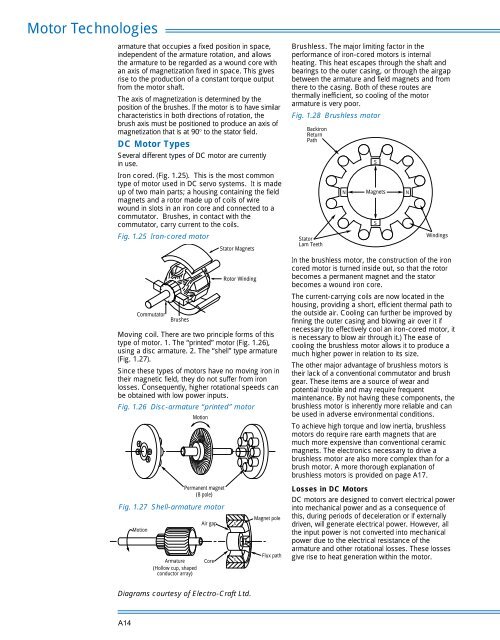
Iron cored. (Fig. 1.25). This is the most common<br />
type of motor used in DC servo systems. It is made<br />
up of two main parts; a housing containing the field<br />
magnets <strong>and</strong> a rotor made up of coils of wire<br />
wound in slots in an iron core <strong>and</strong> connected to a<br />
commutator. Brushes, in contact with the<br />
commutator, carry current to the coils.<br />
Fig. 1.25 Iron-cored motor<br />
Commutator<br />
Brushes<br />
Stator Magnets<br />
Rotor Winding<br />
Moving coil. There are two principle forms of this<br />
type of motor. 1. The “printed” motor (Fig. 1.26),<br />
using a disc armature. 2. The “shell” type armature<br />
(Fig. 1.27).<br />
Since these types of motors have no moving iron in<br />
their magnetic field, they do not suffer from iron<br />
losses. Consequently, higher rotational speeds can<br />
be obtained with low power inputs.<br />
Fig. 1.26 Disc-armature “printed” motor<br />
Motion<br />
Brushless. The major limiting factor in the<br />
performance of iron-cored motors is internal<br />
heating. This heat escapes through the shaft <strong>and</strong><br />
bearings to the outer casing, or through the airgap<br />
between the armature <strong>and</strong> field magnets <strong>and</strong> from<br />
there to the casing. Both of these routes are<br />
thermally inefficient, so cooling of the motor<br />
armature is very poor.<br />
Fig. 1.28 Brushless motor<br />
Backiron<br />
Return<br />
Path<br />
Stator<br />
Lam Teeth<br />
N<br />
In the brushless motor, the construction of the iron<br />
cored motor is turned inside out, so that the rotor<br />
becomes a permanent magnet <strong>and</strong> the stator<br />
becomes a wound iron core.<br />
The current-carrying coils are now located in the<br />
housing, providing a short, efficient thermal path to<br />
the outside air. Cooling can further be improved by<br />
finning the outer casing <strong>and</strong> blowing air over it if<br />
necessary (to effectively cool an iron-cored motor, it<br />
is necessary to blow air through it.) The ease of<br />
cooling the brushless motor allows it to produce a<br />
much higher power in relation to its size.<br />
The other major advantage of brushless motors is<br />
their lack of a conventional commutator <strong>and</strong> brush<br />
gear. These items are a source of wear <strong>and</strong><br />
potential trouble <strong>and</strong> may require frequent<br />
maintenance. By not having these components, the<br />
brushless motor is inherently more reliable <strong>and</strong> can<br />
be used in adverse environmental conditions.<br />
To achieve high torque <strong>and</strong> low inertia, brushless<br />
motors do require rare earth magnets that are<br />
much more expensive than conventional ceramic<br />
magnets. The electronics necessary to drive a<br />
brushless motor are also more complex than for a<br />
brush motor. A more thorough explanation of<br />
brushless motors is provided on page A17.<br />
S<br />
Magnets<br />
S<br />
N<br />
Windings<br />
Motion<br />
Armature<br />
(Hollow cup, shaped<br />
conductor array)<br />
Permanent magnet<br />
(8 pole)<br />
Fig. 1.27 Shell-armature motor<br />
Air gap<br />
Core<br />
S<br />
S<br />
Magnet pole<br />
Flux path<br />
Losses in DC <strong>Motor</strong>s<br />
DC motors are designed to convert electrical power<br />
into mechanical power <strong>and</strong> as a consequence of<br />
this, during periods of deceleration or if externally<br />
driven, will generate electrical power. However, all<br />
the input power is not converted into mechanical<br />
power due to the electrical resistance of the<br />
armature <strong>and</strong> other rotational losses. These losses<br />
give rise to heat generation within the motor.<br />
Diagrams courtesy of Electro-Craft Ltd.<br />
A14