Compumotor Step Motor & Servo Motor Systems and Controls
Compumotor Step Motor & Servo Motor Systems and Controls
Compumotor Step Motor & Servo Motor Systems and Controls

Create successful ePaper yourself
Turn your PDF publications into a flip-book with our unique Google optimized e-Paper software.
<strong>Motor</strong> Technologies<br />
Repeating the sequence in the example will cause<br />
the forcer to continue its movement. When the<br />
sequence is stopped, the forcer stops with the<br />
appropriate tooth set aligned. At rest, the forcer<br />
develops a holding force that opposes any attempt<br />
to displace it. As the resting motor is displaced from<br />
equilibrium, the restoring force increases until the<br />
displacement reaches one-quarter of a tooth<br />
interval. (See Fig. 1.18.) Beyond this point, the<br />
restoring force drops. If the motor is pushed over<br />
the crest of its holding force, it slips or jumps rather<br />
sharply <strong>and</strong> comes to rest at an integral number of<br />
tooth intervals away from its original location. If this<br />
occurs while the forcer is travelling along the platen,<br />
it is referred to as a stall condition.<br />
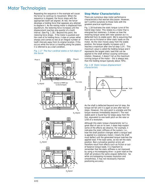
Fig. 1.17 The four cardinal states or full steps of<br />
the forcer<br />
Phase A<br />
N<br />
S<br />
Phase B<br />
<strong>Step</strong> <strong>Motor</strong> Characteristics<br />
There are numerous step motor performance<br />
characteristics that warrant discussion. However,<br />
we’ll confine ourselves to those traits with the<br />
greatest practical significance.<br />
Fig. 1.18 illustrates the static torque curve of the<br />
hybrid step motor. This relates to a motor that is<br />
energized but stationary. It shows us how the<br />
restoring torque varies with rotor position as it is<br />
deflected from its stable point. We’re assuming that<br />
there are no frictional or other static loads on the<br />
motor. As the rotor moves away from the stable<br />
position, the torque steadily increases until it<br />
reaches a maximum after one full step (1.8°). This<br />
maximum value is called the holding torque <strong>and</strong> it<br />
represents the largest static load that can be<br />
applied to the shaft without causing continuous<br />
rotation. However, it doesn’t tell us the maximum<br />
running torque of the motor – this is always less<br />
than the holding torque (typically about 70%).<br />
Fig. 1.18 Static torque-displacement<br />
characteristic<br />
A 1 Aligned<br />
Direction of MMF due <br />
to electromagnet<br />
N<br />
S<br />
Flux Lines<br />
Torque<br />
Clockwise Counter Clockwise<br />
Stable<br />
Max<br />
Torque<br />
4 <strong>Motor</strong> <strong>Step</strong>s<br />
Unstable<br />
Stable<br />
Angle<br />
B 2 Aligned<br />
As the shaft is deflected beyond one full step, the<br />
torque will fall until it is again at zero after two full<br />
steps. However, this zero point is unstable <strong>and</strong> the<br />
torque reverses immediately beyond it. The next<br />
stable point is found four full steps away from the<br />
first, equivalent to one tooth pitch on the rotor or<br />
1/50 of a revolution.<br />
A Aligned<br />
2<br />
N<br />
N<br />
S<br />
S<br />
Although this static torque characteristic isn’t a<br />
great deal of use on its own, it does help explain<br />
some of the effects we observe. For example, it<br />
indicates the static stiffness of the system, (i.e.,<br />
how the shaft position changes when a torque load<br />
is applied to a stationary motor). Clearly the shaft<br />
must deflect until the generated torque matches the<br />
applied load. If the load varies, so too will the static<br />
position. Non-cumulative position errors will<br />
therefore result from effects such as friction or outof-balance<br />
torque loads. It is important to<br />
remember that the static stiffness is not improved<br />
by using a microstepping drive—a given load on the<br />
shaft will produce the same angular deflection. So<br />
while microstepping increases resolution <strong>and</strong><br />
smoothness, it may not necessarily improve<br />
positioning accuracy.<br />
B Aligned<br />
1<br />
A10