Compumotor Step Motor & Servo Motor Systems and Controls
Compumotor Step Motor & Servo Motor Systems and Controls
Compumotor Step Motor & Servo Motor Systems and Controls

You also want an ePaper? Increase the reach of your titles
YUMPU automatically turns print PDFs into web optimized ePapers that Google loves.
Drive Technologies<br />
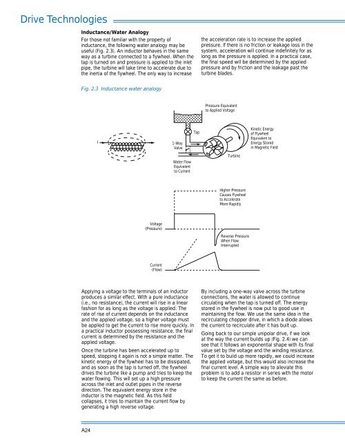
Inductance/Water Analogy<br />
For those not familiar with the property of<br />
inductance, the following water analogy may be<br />
useful (Fig. 2.3). An inductor behaves in the same<br />
way as a turbine connected to a flywheel. When the<br />
tap is turned on <strong>and</strong> pressure is applied to the inlet<br />
pipe, the turbine will take time to accelerate due to<br />
the inertia of the flywheel. The only way to increase<br />
the acceleration rate is to increase the applied<br />
pressure. If there is no friction or leakage loss in the<br />
system, acceleration will continue indefinitely for as<br />
long as the pressure is applied. In a practical case,<br />
the final speed will be determined by the applied<br />
pressure <strong>and</strong> by friction <strong>and</strong> the leakage past the<br />
turbine blades.<br />
Fig. 2.3 Inductance water analogy<br />
Pressure Equivalent<br />
to Applied Voltage<br />
I<br />
1-Way<br />
Valve<br />
Tap<br />
Kinetic Energy<br />
of Flywheel<br />
Equivalent to<br />
Energy Stored<br />
in Magnetic Field<br />
Water Flow<br />
Equivalent<br />
to Current<br />
Turbine<br />
Higher Pressure<br />
Causes Flywheel<br />
to Accelerate<br />
More Rapidly<br />
Voltage<br />
(Pressure)<br />
Reverse Pressure<br />
When Flow<br />
Interrupted<br />
Current<br />
(Flow)<br />
Applying a voltage to the terminals of an inductor<br />
produces a similar effect. With a pure inductance<br />
(i.e., no resistance), the current will rise in a linear<br />
fashion for as long as the voltage is applied. The<br />
rate of rise of current depends on the inductance<br />
<strong>and</strong> the applied voltage, so a higher voltage must<br />
be applied to get the current to rise more quickly. In<br />
a practical inductor possessing resistance, the final<br />
current is determined by the resistance <strong>and</strong> the<br />
applied voltage.<br />
Once the turbine has been accelerated up to<br />
speed, stopping it again is not a simple matter. The<br />
kinetic energy of the flywheel has to be dissipated,<br />
<strong>and</strong> as soon as the tap is turned off, the flywheel<br />
drives the turbine like a pump <strong>and</strong> tries to keep the<br />
water flowing. This will set up a high pressure<br />
across the inlet <strong>and</strong> outlet pipes in the reverse<br />
direction. The equivalent energy store in the<br />
inductor is the magnetic field. As this field<br />
collapses, it tries to maintain the current flow by<br />
generating a high reverse voltage.<br />
By including a one-way valve across the turbine<br />
connections, the water is allowed to continue<br />
circulating when the tap is turned off. The energy<br />
stored in the flywheel is now put to good use in<br />
maintaining the flow. We use the same idea in the<br />
recirculating chopper drive, in which a diode allows<br />
the current to recirculate after it has built up.<br />
Going back to our simple unipolar drive, if we look<br />
at the way the current builds up (Fig. 2.4) we can<br />
see that it follows an exponential shape with its final<br />
value set by the voltage <strong>and</strong> the winding resistance.<br />
To get it to build up more rapidly, we could increase<br />
the applied voltage, but this would also increase the<br />
final current level. A simple way to alleviate this<br />
problem is to add a resistor in series with the motor<br />
to keep the current the same as before.<br />
A24