Compumotor Step Motor & Servo Motor Systems and Controls
Compumotor Step Motor & Servo Motor Systems and Controls
Compumotor Step Motor & Servo Motor Systems and Controls

You also want an ePaper? Increase the reach of your titles
YUMPU automatically turns print PDFs into web optimized ePapers that Google loves.
<strong>Motor</strong> Technologies<br />
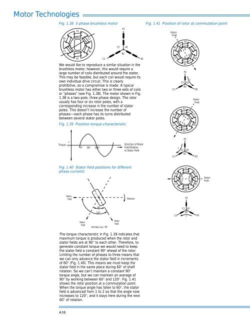
Fig. 1.38 3-phase brushless motor<br />
A1<br />
B2<br />
C2<br />
A1<br />
Fig. 1.41 Position of rotor at commutation point<br />
Stator<br />
Field<br />
A1<br />
C1<br />
A2<br />
B1<br />
C1<br />
C2<br />
B2<br />
A2<br />
B1<br />
B2<br />
C1<br />
N<br />
N<br />
S<br />
S<br />
C2<br />
B1<br />
We would like to reproduce a similar situation in the<br />
brushless motor; however, this would require a<br />
large number of coils distributed around the stator.<br />
This may be feasible, but each coil would require its<br />
own individual drive circuit. This is clearly<br />
prohibitive, so a compromise is made. A typical<br />
brushless motor has either two or three sets of coils<br />
or “phases” (see Fig. 1.38). The motor shown in Fig.<br />
1.38 is a two-pole, three-phase design. The rotor<br />
usually has four or six rotor poles, with a<br />
corresponding increase in the number of stator<br />
poles. This doesn’t increase the number of<br />
phases—each phase has its turns distributed<br />
between several stator poles.<br />
Fig. 1.39 Position-torque characteristic<br />
C1<br />
B2<br />
C1<br />
A2<br />
A1<br />
I<br />
C2 A2<br />
B2<br />
A1<br />
N<br />
N<br />
S<br />
S<br />
C2<br />
B1<br />
B1<br />
Stator<br />
Field<br />
A2<br />
Torque<br />
+<br />
-<br />
0°<br />
90°<br />
180°<br />
Direction of Rotor<br />
Field Relative<br />
to Stator Field<br />
C1<br />
I<br />
A1<br />
C2 A2<br />
B2<br />
B1<br />
Fig. 1.40 Stator field positions for different<br />
phase currents<br />
B2<br />
C1<br />
S<br />
S<br />
A1<br />
N<br />
N<br />
C2<br />
B1<br />
Stator<br />
Field<br />
A2<br />
Stator<br />
Field<br />
S<br />
N<br />
Rotation<br />
A1<br />
60°<br />
120°<br />
C1<br />
C2 A2<br />
B2<br />
I<br />
B1<br />
Stator<br />
Field<br />
Average Lag = 90°<br />
Rotor<br />
Field<br />
The torque characteristic in Fig. 1.39 indicates that<br />
maximum torque is produced when the rotor <strong>and</strong><br />
stator fields are at 90° to each other. Therefore, to<br />
generate constant torque we would need to keep<br />
the stator field a constant 90° ahead of the rotor.<br />
Limiting the number of phases to three means that<br />
we can only advance the stator field in increments<br />
of 60° (Fig. 1.40). This means we must keep the<br />
stator field in the same place during 60° of shaft<br />
rotation. So we can’t maintain a constant 90°<br />
torque angle, but we can maintain an average of<br />
90° by working between 60° <strong>and</strong> 120°. Fig. 1.41<br />
shows the rotor position at a commutation point.<br />
When the torque angle has fallen to 60°, the stator<br />
field is advanced from 1 to 2 so that the angle now<br />
increases to 120°, <strong>and</strong> it stays here during the next<br />
60° of rotation.<br />
A18