Compumotor Step Motor & Servo Motor Systems and Controls
Compumotor Step Motor & Servo Motor Systems and Controls
Compumotor Step Motor & Servo Motor Systems and Controls

You also want an ePaper? Increase the reach of your titles
YUMPU automatically turns print PDFs into web optimized ePapers that Google loves.
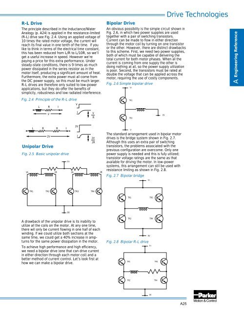
R-L Drive<br />
The principle described in the Inductance/Water<br />
Analogy (p. A24) is applied in the resistance-limited<br />
(R-L) drive see Fig. 2.4. Using an applied voltage of<br />
10 times the rated motor voltage, the current will<br />
reach its final value in one tenth of the time. If you<br />
like to think in terms of the electrical time constant,<br />
this has been reduced from L/R to L/10R, so we’ll<br />
get a useful increase in speed. However we’re<br />
paying a price for this extra performance. Under<br />
steady-state conditions, there is 9 times as much<br />
power dissipated in the series resistor as in the<br />
motor itself, producing a significant amount of heat.<br />
Furthermore, the extra power must all come from<br />
the DC power supply, so this must be much larger.<br />
R-L drives are therefore only suited to low-power<br />
applications, but they do offer the benefits of<br />
simplicity, robustness <strong>and</strong> low radiated interference.<br />
Fig. 2.4 Principle of the R-L drive<br />
L<br />
R<br />
V<br />
I<br />
V<br />
I<br />
V<br />
R<br />
Bipolar Drive<br />
An obvious possibility is the simple circuit shown in<br />
Fig. 2.6, in which two power supplies are used<br />
together with a pair of switching transistors.<br />
Current can be made to flow in either direction<br />
through the motor coil by turning on one transistor<br />
or the other. However, there are distinct drawbacks<br />
to this scheme. First, we need two power supplies,<br />
both of which must be capable of delivering the<br />
total current for both motor phases. When all the<br />
current is coming from one supply the other is<br />
doing nothing at all, so the power supply utilization<br />
is poor. Second, the transistors must be rated at<br />
double the voltage that can be applied across the<br />
motor, requiring the use of costly components.<br />
Fig. 2.6 Simple bipolar drive<br />
V+<br />
TR1<br />
TR2<br />
0V<br />
Drive Technologies<br />
A Engineering Reference<br />
L R R I<br />
2V<br />
Unipolar Drive<br />
Fig. 2.5 Basic unipolar drive<br />
V+<br />
1A<br />
1B<br />
2A<br />
2V<br />
I<br />
2V<br />
2R<br />
2B<br />
The st<strong>and</strong>ard arrangement used in bipolar motor<br />
drives is the bridge system shown in Fig. 2.7.<br />
Although this uses an extra pair of switching<br />
transistors, the problems associated with the<br />
previous configuration are overcome. Only one<br />
power supply is needed <strong>and</strong> this is fully utilized;<br />
transistor voltage ratings are the same as that<br />
available for driving the motor. In low-power<br />
systems, this arrangement can still be used with<br />
resistance limiting as shown in Fig. 2.8.<br />
Fig. 2.7 Bipolar bridge<br />
V-<br />
V+<br />
TR1 TR2 TR3 TR4<br />
TR1<br />
TR3<br />
0V<br />
A drawback of the unipolar drive is its inability to<br />
utilize all the coils on the motor. At any one time,<br />
there will only be current flowing in one half of each<br />
winding. If we could utilize both sections at the<br />
same time, we could get a 40% increase in ampturns<br />
for the same power dissipation in the motor.<br />
To achieve high performance <strong>and</strong> high efficiency,<br />
we need a bipolar drive (one that can drive current<br />
in either direction through each motor coil) <strong>and</strong> a<br />
better method of current control. Let’s look first at<br />
how we can make a bipolar drive.<br />
TR2<br />
TR4<br />
0V<br />
Fig. 2.8 Bipolar R-L drive<br />
V+<br />
TR1<br />
TR3<br />
TR2<br />
TR4<br />
0V<br />
A25