C123 Copiers... Introduction - The Parts Drop
C123 Copiers... Introduction - The Parts Drop
C123 Copiers... Introduction - The Parts Drop

You also want an ePaper? Increase the reach of your titles
YUMPU automatically turns print PDFs into web optimized ePapers that Google loves.
www.partsdrop.com<br />
201-387-7776<br />
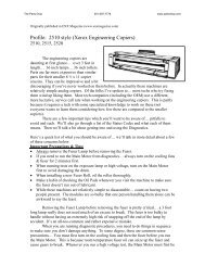
Introducing: Xerox <strong>C123</strong> style… <strong>Introduction</strong> & Status<br />
Code Meanings for the Xerox CopyCentre <strong>C123</strong>, C128, &<br />
WorkCentre M123, M128, Pro123, Pro128.<br />
Last month we wrapped up a relatively quick look at the C118 style<br />
(C118, C118i, M118, M118i). This month we’ll start a more in-depth<br />
look at a series of models which look at first to have a lot in common<br />
with the C118. In fact it turns out that they are far more different than<br />
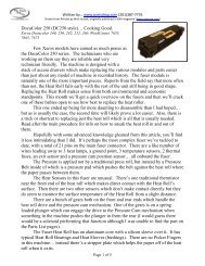
Xerox <strong>C123</strong><br />
expected. We’ll do a bit of an introduction: contrasting them with the C118’s and going over<br />
the machine’s capabilities and supplies. <strong>The</strong>n it’ll be time to go through the Status Codes to<br />
get some bearing on their meanings.<br />
<strong>The</strong> model numbers which are in the <strong>C123</strong> style include: CopyCentre <strong>C123</strong>, C128,<br />
133, WorkCentre M123, M128, M133, Pro123, Pro128, and Pro133. I should mention that<br />
the 133 models are not mentioned in the 2004 release of the Service Manual which was used<br />
as the primary reference material for this article (available on Xerox’s Documentation<br />
Website www.xdss.com under part number 701P26490 for $388.87). Considering that they<br />
are a newer release which shares the same supply part numbers, it stands to reason that most<br />
of what is in this article will apply to the 133’s.<br />
<strong>The</strong> <strong>C123</strong> style machines are being welcomed<br />
with more warmth than the C118’s before them.<br />
Several technicians who are selling and servicing them<br />
reported them as being excellent machines. <strong>The</strong><br />
opposite was said of the C118 machines. <strong>The</strong>se newcomers,<br />
I am told, are workhorses which give very little<br />
in the way of problems. <strong>The</strong>y are also rather technician<br />
friendly. <strong>The</strong> two types of machine share a similar<br />
appearance. <strong>The</strong>y actually use the same part number<br />
for the drum cartridges… but that is where the similarities<br />
pretty much dry up. <strong>The</strong> Status Codes and Diagnostic Codes<br />
of the <strong>C123</strong> are completely alien to the ones for the C118.<br />
Feed components are similar in some of the trays, but the<br />
Document Feeder parts are nothing alike. <strong>The</strong> Toner<br />
Cartridges look similar although the <strong>C123</strong> is considerably<br />
larger and uses a different CRUM (Customer Replaceable<br />
Unit Monitors… the chips which track the count and identify<br />
the version of the cartridge). <strong>The</strong> same is true of the newest<br />
ones… the WC-5225 style. <strong>The</strong> <strong>C123</strong> series machines<br />
are selling heavily out there…. So they’ll be showing up<br />
in greater numbers than the C118’s.<br />
<strong>The</strong>re is also a Phaser printer which is related to<br />
the <strong>C123</strong>. <strong>The</strong> Phaser 5500 is the same basic engine,<br />
with the main difference being that there is a simpler<br />
User Interface (no touchscreen) and no Scanner up top.<br />
Naturally with the different User Interface, the<br />
diagnostics will be quite different as well.<br />
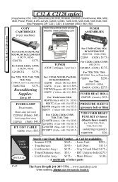
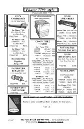
<strong>C123</strong> style Toner Cartridge<br />
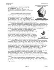
RF CRUM<br />
Found on Toner & Drum Ctgs.<br />
Page 1 of 11<br />
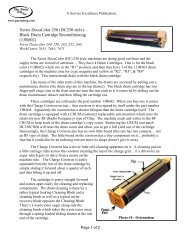
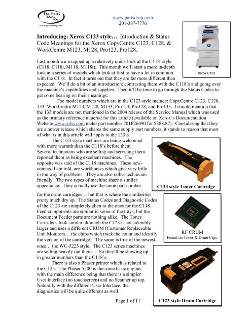
<strong>C123</strong> style Drum Cartridge
www.partsdrop.com<br />
201-387-7776<br />
<strong>The</strong> Supplies for the <strong>C123</strong> style are very close to the C118. <strong>The</strong> Drum Cartridge is<br />
actually identical right down to the part number (13R589). It has a yield of 60K and sells for<br />
$199.-. <strong>The</strong> Phaser 5500 version of the Drum Cartridge (113R670) will be different<br />
(probably just the CRUM will be different). <strong>The</strong> Toner Cartridge (6R1184) are physically<br />
different between the C118 (6R1179), & <strong>C123</strong> (6R1184). <strong>The</strong> Phaser 5500 (113R668) &<br />
Phaser 5550 & the WC-5222/5225/5230 all have the same cartridge as the <strong>C123</strong> but the<br />
CCRUM is unique on each so you can’t freely interchange them. <strong>The</strong> CRUMS (Customer<br />
Replaceable Unit Monitors) used on both the Drum and Toner Cartridges on these machines<br />
are RF (Radio Frequency) types of chips… <strong>The</strong>y never makes any physical electrical<br />
connection whatsoever. Instead the machine uses radio waves of some sort to read and write<br />
to the CRUM’s chip.<br />
<strong>The</strong> Developer station (yep, it’s dual component, so it actually does have developer<br />
material) is spared as part of the Drum Cartridge. <strong>The</strong>y call the Drum Cartridge the<br />
“Xero/Developer Cartridge” at times in the Service Manual. <strong>The</strong> Toner cartridges have a<br />
small bit of Developer material mixed into them so the material remains fresh in the machine<br />
throughout the life of the Drum Cartridge (Xero / Developer Ctg).<br />
Now for the Status Codes. This list will have to be abbreviated somewhat because the<br />
Service Manual acknowledges over 600 Status Codes. <strong>The</strong> general meanings of all of the<br />
code prefixes will be represented as the first part of the code (the prefix), then a dash followed<br />
by “xxx” to represent the second half of the code (example 010-xxx). Those generalizations<br />
will be in bold text in the table to follow.<br />
<strong>The</strong> book is littered with acronyms, and although there is a Glossary of Terms, many<br />
of the acronyms which I couldn’t guess the meaning to, are not listed. It was getting<br />
frustrating till my wife suggested that I Google the acronyms… actually found quite a few of<br />
them. Good thinking Joann!<br />
Status Codes / Indicators:<br />
Code Description<br />
003-xxx Communication Failures<br />
003-942 Document size auto-detect failure<br />
005-xxx Document Feeder Problems<br />
010-xxx Fuser Problems<br />
010-313 Fuser Control <strong>The</strong>rmistor failure (open Control <strong>The</strong>rmistor)<br />
010-314 Fuser Side <strong>The</strong>rmistor failure (open Side <strong>The</strong>rmistor)<br />
010-318 Fuser temperature did not rise quickly enough during heating cycle<br />
Fuser Overheat (must be reset from diagnostics by resetting NVM (Non Volatile<br />
010-320* Memory code 744-220 back to "0") *<br />
Fuser took too long to warm up (must be reset from diagnostics by resetting NVM<br />
010-327* (Non Volatile Memory code 744-220 back to "0") *<br />
010-398 Fuser Fan failure<br />
012-xxx Finisher Problems<br />
016-xxx Fax Service Problems<br />
021-xxx Fax Problems<br />
IOT (Image Output Terminal - print main logic board) - ESS (Electronic Switching<br />
024-xxx System - Network Module) Communication Errors<br />
Tray 1 paper size mismatch (length of paper is seen as different than what the<br />
024-910 paper size switch sees)<br />
024-911 Tray 2 paper size mismatch (length of paper is seen as different than what the<br />
Page 2 of 11
www.partsdrop.com<br />
201-387-7776<br />
paper size switch sees)<br />
Tray 3 paper size mismatch (length of paper is seen as different than what the<br />
024-912 paper size switch sees)<br />
Tray 4 paper size mismatch (length of paper is seen as different than what the<br />
024-913 paper size switch sees)<br />
Face Up Catch Tray closed during copy run when paper was sent to the Face Up<br />
024-919 Tray<br />
024-946 Tray 1 - Tray not detected<br />
024-947 Tray 2 - Tray not detected<br />
024-948 Tray 3 - Tray not detected<br />
024-949 Tray 4 - Tray not detected<br />
024-950 Tray 1 empty<br />
024-951 Tray 2 empty<br />
024-952 Tray 3 empty<br />
024-953 Tray 4 empty<br />
024-954 MPT (Manual Paper Tray / Bypass Tray) empty<br />
024-958 MPT (Manual Paper Tray) paper size failure<br />
024-959 Tray 1 paper size not detected by the paper size sensor<br />
024-960 Tray 2 paper size not detected by the paper size sensor<br />
024-961 Tray 3 paper size not detected by the paper size sensor<br />
024-962 Tray 4 paper size not detected by the paper size sensor<br />
024-985 MPT (Manual Paper Tray / Bypass Tray) feed failure<br />
025-xxx Hard Drive Failures<br />
027-xxx Email Errors<br />
033-xxx Fax Control Errors<br />
034-xxx Fax Communication Problems<br />
035-xxx Fax Network Problems<br />
036-xxx Fax Paramaters Problems<br />
041-xxx NVM (Non Volatile Memory) Errors<br />
042-323 Drum Drive Motor Failure<br />
042-325 Main Drive Motor Failure<br />
Options Communication Errors (Main Board to Duplex Module, Trays Module, Exit<br />
047-xxx Module, Finisher, etc.<br />
047-211 /<br />
212 Communication Failure with OCT (Oscillating Catch Tray)<br />
047-213 Different Finisher detected<br />
047-214 Communication Failure with Duplex Module (DM)<br />
047-215 Communication Failure with Exit Board<br />
047-216 Communication Failure with Finisher<br />
047-218 Communication Failure with TM (Tray Module)<br />
061-315 ROS (Raster Output Scanner - Laser Unit) laser intensity detected as being low.<br />
061-321 ROS (Laser Unit) Motor Failure<br />
061-333 ROS (Laser Unit) Fan Failure<br />
062-xxx Scanner Problems (IIT or Image Input Terminal)<br />
062-277 Scanner to Document Feeder (DADF) Communication Failure<br />
062-300 Platen Interlock is Open<br />
062-310 Scanner Communication Error<br />
062-360 Exposure Carriage Position Failure<br />
062-371 Exposure Lamp Failure<br />
062-380 /<br />
386<br />
Lens CCD (Charge Coupled Device… that is the piece which reads the image)<br />
Output Error<br />
Page 3 of 11
www.partsdrop.com<br />
201-387-7776<br />
062-389 Exposure Carriage Overrun Failure<br />
062-392 /<br />
393 Scanner Logic Board Failures<br />
071-105 Tray 1 Misfeed<br />
071-210 Tray 1 Lift Failure<br />
071-211 Tray 1 Paper Size Switch Failure<br />
072-101 Tray 2 Misfeed<br />
072-105 Paper Jam from Tray 2 (sheet did not reach Registration Sensor in time)<br />
072-210 Tray 2 Lift Failure<br />
072-211 Tray 2 Paper Size Switch Failure<br />
073-101 Tray 3 Misfeed<br />
073-102 Paper Jam from Tray 3 (sheet did not reach the Registration Sensor in time)<br />
073-105 Paper Jam from Tray 3 (sheet did not reach Tray 2 Takeaway Sensor in time)<br />
073-210 Tray 3 Lift Failure<br />
073-211 Tray 3 Paper Size Switch Failure<br />
074-101 Tray 4 Misfeed<br />
074-102 Paper Jam from Tray 4 (sheet did not reach Tray 2 Takeaway Sensor in time)<br />
074-103 Paper Jam from Tray 4 (sheet did not reach Tray 3 Takeaway Sensor in time)<br />
074-105 Paper Jam from Tray 4 (sheet did not reach Registration Sensor in time)<br />
074-210 Tray 3 Lift Failure<br />
074-211 Tray 3 Paper Size Switch Failure<br />
075-135 Bypass Misfeed (from the MPT (Manual Paper Tray))<br />
077-xxx Paper Jams and Interlocks Open.<br />
077-101 Paper Jam, paper not seen leaving the Registration Sensor in time<br />
077-103 Paper Jam, paper not seen leaving the Exit Sensor in time<br />
077-104 Paper Jam, paper seen leaving Exit Sensor earlier than expected<br />
077-106 Paper Jam, paper not seen at Exit Sensor<br />
077-129 Paper Jam when duplexing<br />
077-130 Duplex Exit Sensor Jam<br />
077-131 Duplex Wait Sensor (Duplex Feed)<br />
077-300 Front Door Interlock Open<br />
077-301 Left Door Interlock Open<br />
077-305 Tray Module left hand cover interlock<br />
077-307 Duplex Cover Open<br />
077-308 Left Door (upper) Interlock Open.<br />
077-309 Left Door (lower) Intlock Open<br />
077-329 Main Motor remains on when it is supposed to be off<br />
077-900 Paper detected sitting on the Registration Sensor<br />
077-901 Paper detected sitting on theFuser Exit Sensor<br />
077-902 Paper detected sitting on the Post Fuser Exit Sensor<br />
077-904 Paper detected sitting on the Tray 2 Takeaway Sensor<br />
077-905 Paper detected sitting on the Tray 3 Takeaway Sensor<br />
077-906 Paper detected sitting on the Tray 4 Feed Sensor<br />
077-907 Paper detected on the Duplex Sensor<br />
091-401 Drum is near end of life (the count is about to expire on the CRUM)<br />
091-912 Drum Cartridge is not present (or not seated properly)<br />
091-913 Drum Cartridge end of life (time to replace the cartridge or at least the CRUM)<br />
091-914 Drum Cartridge CRUM communication failure<br />
091-915 <strong>The</strong> machine failed to write to the Drum Cartridge CRUM<br />
091-916 Wrong Drum Cartridge type was detected (for example if you installed a European<br />
Page 4 of 11
www.partsdrop.com<br />
201-387-7776<br />
cartridge in a US machine)<br />
092-910 ATC (Automatic Toner Concentration) Sensor Failure<br />
Toner dispense failure - density did not rise after the toner dispense motor turned<br />
093-312 on<br />
093-406 Low Toner condition sensed (replace cartridge soon)<br />
093-912 Toner Cartridge is empty<br />
093-924 Toner Cartridge CRUM communication failure<br />
093-925 <strong>The</strong> machine failed to write to the Toner Cartridge CRUM<br />
Wrong Toner Cartridge type was detected (for example if you installed a C118 ctg<br />
093-926 in a <strong>C123</strong> machine)<br />
User Interface failures (some of them indicate failure to communicate with the ESS<br />
102-xxx or Network Controller<br />
Printing Control Failures having mostly to do with the Hard Disk Drive, ESS<br />
116-xxx (network controller) or software<br />
Foreign Interface problems (communications with an external device such as a<br />
121-xxx card reader or auditron)<br />
123-xxx Software problems<br />
124-xxx ROM / RAM failures<br />
127-xxx More Software related problems<br />
133-xxx More Fax Control Errors<br />
134-xxx Fax Card failures<br />
202-399 Internal Timer failure<br />
As noted above, some of the fuser codes need to be reset from the diagnostic mode before the<br />
machine will attempt to warm up again. We’ll be getting into the diagnostics in the next<br />
article, but I think that you should at least know how to use the diagnostics to get the fuser<br />
codes to reset… Don’t want to leave you hanging!<br />
* Resetting Fuser Codes (010-320, & 010-327) : (reset NVM code 744-220 to ‘0’)<br />
First enter UI (User Interface) Diagnostic Mode: Hold down the ‘0’ button for 5 seconds and<br />
then press the ‘Start’ button while still holding the ‘0’<br />
button. <strong>The</strong> machine will prompt you for a Password.<br />
Enter the default Access Number: ‘6789’ and press<br />
“Confirm”. <strong>The</strong> colors on the display will be reversed to<br />
indicate that you are now in diagnostic mode. Next press<br />
the “Log In/Out” button on the Control Panel. Select<br />
‘System Settings’, ‘Common’ Settings, followed by<br />
‘Maintenance / Diagnostics’. Now you will find the main<br />
menu includes one choice called “NVM Read / Write”<br />
(NVM is Non Volatile Memory)… Now you can enter<br />
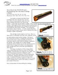
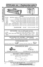
<strong>C123</strong> style Fuser Module<br />
your “Chain-Link” code (in this case 744-220) and press ‘Confirm / Change’. <strong>The</strong> current<br />
value will appear (if the machine is in a fuser fault condition, the value will be set to “1”).<br />
Select the “New Value” column and input your new value (‘0’). Select “Save” and the new<br />
number should now appear in the “Current Value” column. You can turn the power off and<br />
back on at this point. <strong>The</strong> machine will attempt to warm up the fuser again. If the condition<br />
which caused the fault in the first place is still happening, the Status Code will return after a<br />
few minutes of attempting to warm up.<br />
Page 5 of 11
www.partsdrop.com<br />
201-387-7776<br />
That’s a wrap. For this month anyhow… will delve into the diagnostics more in the next<br />
article. As these machines begin needing service, I think we’ll all be ready. See you next<br />
month!<br />
Introducing: Xerox <strong>C123</strong> style… (Part II) Diagnostics,<br />
Adjustment Codes and Procedures for the Xerox CopyCentre<br />
<strong>C123</strong>, C128, & WorkCentre M123, M128, Pro123, Pro128.<br />
Last month we got things started with the <strong>C123</strong> style. We did an<br />
overview of the machine and took a peek at the Status Code meanings.<br />
This series is getting good reviews from the folks who have been<br />
Xerox <strong>C123</strong><br />
placing and repairing them, so it seems that they will prove to be worth<br />
learning. This time, let’s hit the diagnostic memory adjustment codes. This should be kind of<br />
interesting… I’ll have to trim the list down a bit from a rather unwieldy 1000+ codes (give or<br />
take a few) to something which remains useful to the folks who are out there fixing them in<br />
the field.<br />
<strong>The</strong> diagnostic entry process is the same as the C118 machines (we covered those in a<br />
previous article) but that’s where the diagnostic similarities end. To get into “UI Diagnostic<br />
Mode” (UI stands for User Interface) from the powered on state, press and hold down the ‘0’<br />
key for 5 seconds, then press the ‘Start’ button while still holding the ‘0’. <strong>The</strong> screen will<br />
prompt you for a Password. Enter the default access number (6789) and press “Confirm”.<br />
<strong>The</strong> colors on the display will reverse to show you that the machine is now in diagnostic<br />
mode.<br />
To run a Service Report, you’ll then press the “Machine Status” button on the control<br />
panel and then select the “Billing Meters / Print Reports” tab on the display. <strong>The</strong>n press<br />
“Print Reports / List” button followed by the “CE” button. You can print out the following<br />
reports:<br />
• HFSI Report (High Frequency Service Items)<br />
• Jam Report<br />
• Failure Report (shows the # of times each fault occurred)<br />
• Shutdown Report (this is the Fault History which will show which Status Codes have<br />
come up recently and when they occurred)<br />
After running whatever reports you want to glean from the machine, turn the power off and<br />
back on to exit the diagnostic mode.<br />
Now, for the rest of the Diagnostics, you’ll enter Diagnostic Mode but this time, you’ll<br />
press ‘Log In/Out’ on the control panel. You can then select “System Settings” followed by<br />
“Common Settings” and then “Maintenance / Diagnostics” which is basically the Main Menu<br />
for our purposes. Within that main menu you’ll find:<br />
• NVM Read/Write: Non Volatile Memory adjustments.<br />
• Component Control: For testing sensors, motors, solenoids, etc.<br />
• Print Test Pattern<br />
• Initialize NVM<br />
Page 6 of 11
www.partsdrop.com<br />
201-387-7776<br />
• Adjustment / Others: Includes: ‘Machine ID / Billing Data’, ‘Initialize the HFSI’<br />
(High Frequency Service Items), ‘Adjust Toner Density’, and ‘Tray 5 (Bypass) guide<br />
adjustment’.<br />
If you then choose “NVM Read / Write”, you’ll be able to get to the adjustments you need to<br />
keep the machine running right. Things like the registration, fuser temperature, etc. <strong>The</strong><br />
codes are 6 digit numbers separated by a hyphen between what is called the “Chain” and the<br />
“Link” (742-027 for example). Enter the “Chain-Link” code you wish to view and select<br />
“Confirm/Change”. <strong>The</strong> current value of your selected code will appear in the “Current<br />
Value” column. To change the setting, you’ll then input a new number in the “New Value”<br />
column and press “Save”.<br />
Here is an abbreviated list of the stuff we generally all want to know… I’ve left off<br />
anything which isn’t critical to regular maintenance and repairs (the fax codes for example are<br />
just too lengthy to get into). For the registration adjustments, the list below includes the ones<br />
which pertain to “plain paper” only, although the Service Manual lists multiple settings for<br />
different heavier weight paper for each tray (there are 32 codes in the book relating to<br />
registration and the list below shows only the 5 most commonly needed codes). <strong>The</strong><br />
following list should suffice to get you through most service calls.<br />
MEMORY ADJUSTMENTS (NVM Read / Write)<br />
NVM<br />
Code Description Default Range 1 count Value meanings<br />
700-089 HDD (Hard Disk Drive) Status 0 0-2<br />
0=Installed, 1=Failed, 2=Not<br />
Installed<br />
700-100 DHCP Mode 2<br />
0=Manual, 4=BOOTP,<br />
2=DHCP, 1=RARP<br />
700-130 Sleep Mode Timer 2 1-240 1 minute 1-240 minutes to sleep mode<br />
700-131 Sleep Mode Available 1 0-1 0=Disabled, 1=Enabled<br />
700-171<br />
Key Operator Tools Entry<br />
Password 11111<br />
700-399<br />
Default unit of measure (mm /<br />
inch) 3 1 = millimeters, 3 = Inches<br />
700-540 Auditron Mode 0 0-3<br />
0=Off, 1=Internal Auditron,<br />
2=Network Accounting<br />
711-140<br />
Document Feeder (DADF) Lead<br />
Edge Registration (side 1) 129 0-214 0.0458mm<br />
711-141<br />
Document Feeder (DADF) Lead<br />
Edge Registration (side 2) 129 0-214 0.0458mm<br />
711-142<br />
Document Feeder (DADF) Trail<br />
Edge (side 1) 129 0-214 0.0458mm<br />
711-143<br />
Document Feeder (DADF) Trail<br />
Edge (side 2) 129 0-214 0.0458mm<br />
715-052 Platen type 2 0-2 0=Flat Top, 1=Doc Belt, 2=CVT<br />
715-720 Copy Density Adjustment 128 0-256<br />
715-721<br />
Copy High Density Adjustment<br />
(darker3 setting) 128 0-256<br />
715-722 Scan / Fax Density Adjustment 128 0-256<br />
715-723<br />
Scan / Fax High Density<br />
Adjustment (darker3 setting) 128 0-256<br />
Page 7 of 11
www.partsdrop.com<br />
201-387-7776<br />
719-008 Market region 0 0-3<br />
Page 8 of 11<br />
0=FX (Fuji Xerox), 1=AP (Asia /<br />
Pacific), XC (Xerox Canada),<br />
XE (Xerox Europe)<br />
0 = Face Down Tray#1, 1 =<br />
Face Down Tray #2, 3 =<br />
Finisher Bin1, 4 = Finisher Top<br />
Tray<br />
Output Configuration (where<br />
740-090 copies are set to be delivered) 0 0-4<br />
741-001 Main and Drum Motor Speed 24 0-53 0.10% 0=-2.7%, 53=2.6%<br />
742-009 Enable Tray 4 0 0-1<br />
Lead Edge Registration (all<br />
742-027 trays) 33 0-66 0.2175mm<br />
742-030 Invert timing (all trays) 33 0-66 0.435mm<br />
742-098 Enable Face Down Tray #2 0 0-1<br />
742-099 Enable Face Up Tray 0 0-1<br />
Fuser Standby Lamp On<br />
744-006 temperature 45 0-99<br />
Fuser Standby Lamp Off<br />
744-010 temperature 20 0-99<br />
744-043 Fuser Ready temperature 35 0-70<br />
Fuser Overtemperature Reset<br />
(Resets 010-320 & 010-327<br />
744-220 Status Codes) 0 0-5<br />
1 degree<br />
C<br />
1 degree<br />
C<br />
1 degree<br />
C<br />
749-523 Side Normal Erase Adjustment 8 0-18 0.254mm<br />
749-524 Top Normal Erase Adjustment 9 0-18 0.217mm<br />
0=Disable Tray 4, 1=Disable<br />
Tray 4<br />
0=-7.18mm, 33=0.0mm,<br />
66=7.18mm<br />
0 = -14.96mm, 33 = 0mm, 66 =<br />
14.96mm<br />
0 = Disable Tray, 1 = Enable<br />
Tray<br />
0 = Disable Tray, 1 = Enable<br />
Tray<br />
default (45) = 175 degrees C<br />
default (20) = 180 degrees C<br />
default (35) = 165 degrees C<br />
0 = Reset, 1 - 5 = Fault<br />
condition<br />
749-527 End Normal Erase Adjustment 9 0-18 0.217mm<br />
ATC (Auto Toner Concentration)<br />
752-954 Sensor 0 0-1 0 = Normal, 1 = Abnormal<br />
760-001<br />
760-002<br />
760-003<br />
Lead Edge Registration (Tray 1,<br />
Plain Paper) 33 0-66 0.2175mm<br />
Lead Edge Registration (Tray 2-<br />
4, HCF, Plain Paper) 33 0-66 0.2175mm<br />
Lead Edge Registration (Bypass<br />
/ MPT Manual Paper Tray) 33 0-66 0.2175mm<br />
0=-7.18mm, 33=0.0mm,<br />
66=7.18mm<br />
0=-7.18mm, 33=0.0mm,<br />
66=7.18mm<br />
0=-7.18mm, 33=0.0mm,<br />
66=7.18mm<br />
0=-7.18mm, 33=0.0mm,<br />
66=7.18mm<br />
760-005 Lead Edge Registration (Duplex) 33 0-66 0.2175mm<br />
770-101 IP Address 0.0.0.0<br />
770-102 Subnet Mask 0.0.0.0<br />
770-103 Gateway Address 0.0.0.0<br />
770-190 Mail Service Start / Stop 1 0-1 0=Stop, 1=Start<br />
770-191 Address of Mail Sender NULL<br />
770-202 SMTP Mail Server IP Address 0.0.0.0<br />
enter email address<br />
(username@domain.name)
www.partsdrop.com<br />
201-387-7776<br />
770-286 POP Server User Name NULL<br />
770-287 POP Server Password NULL<br />
780-060 Tray 1 Priority 1 1-4 prioritize trays from 1 to 4<br />
780-061 Tray 2 Priority 2 1-4 prioritize trays from 1 to 4<br />
780-062 Tray 3 Priority 3 1-4 Prioritize trays from 1 to 4<br />
780-063 Tray 4 Priority 4 1-4 prioritize trays from 1 to 4<br />
780-085 Drum End of Life disable 1 0-1<br />
785-024<br />
Adjust "100%" setting (98-102%)<br />
for Fast Scan 1000<br />
Adjust "100%" setting (98-102%)<br />
for Slow Scan 1000<br />
Page 9 of 11<br />
980-<br />
1020 0.10%<br />
980-<br />
1020 0.10%<br />
1= Stop Printing, 0 = Do not<br />
stop printing<br />
980=98.0%, 1000=100.0%,<br />
1020=102.0%<br />
980=98.0%, 1000=100.0%,<br />
1020=102.0%<br />
785-025<br />
785-080 Edge Erase margin 5 0-10 1mm 0=0mm, 5=5mm, 10=10mm<br />
1=Text, 2=Text & Photo,<br />
3=Photo, 4=Pencil Text<br />
790-094 Default Original Type 1 1-4<br />
790-097 Default Background suppression 1 0-1 0=Off, 1=On<br />
0=Lighter3, 1=Lighter2,<br />
2=Lighter1, 3=Normal,<br />
4=Darker1, 5=Darker2,<br />
6=Darker3<br />
790-098 Default Density Adjustment 3 0-6<br />
790-099 Mixed Size Default 0 0-1 0=Off, 1=On<br />
790-122 Default Sharpness 2 0-4<br />
790-181 Default Duplex Setting 0 0-3<br />
790-183 Default Exit Tray 0 0-3<br />
790-223 Default Color Mode in Scan 1 0-3<br />
Default Scanning Resolution in<br />
790-225 Scan 0 0-4<br />
0=Sharper, 1=Sharp,<br />
2=Normal, 3=Soft, 4=Softer<br />
0=1 to 1 sided, 1= 1 to 2 sided,<br />
2= 2 to 1 sided, 3= 2 to 2 sided<br />
0= Center Tray, 1= Side Tray,<br />
2= Finisher Tray, 3= Center<br />
Tray2<br />
0= Full Color, 1=Grayscale,<br />
2=Text & Photo<br />
0=200dpi, 1=300dpi, 2=400dpi,<br />
3=600dpi, 4=100dpi<br />
0=Higher, 1=High, 2=Standard,<br />
3=Low, 4=Lower<br />
790-230 Contrast Adjust in Scan 2 0-4<br />
Default Background suppression<br />
790-288 in Scan 0 0-1 0=Off, 1=On<br />
0 mm to 50mm in 1mm<br />
790-301 Top Edge Erase in Copy 2 0-50 1mm increments<br />
0 mm to 50mm in 1mm<br />
790-302 Bottom Edge Erase in Copy 2 0-50 1mm increments<br />
0 mm to 50mm in 1mm<br />
790-303 Left Edge Erase in Copy 2 0-50 1mm increments<br />
0 mm to 50mm in 1mm<br />
790-304 Right Edge Erase in Copy 2 0-50 1mm increments<br />
Maintaining Serial Numbers in Diagnostics (clearing 124-315 codes): Maintaining a<br />
consistent machine Serial Number in the diagnostics is important if you are replacing either<br />
the Main Board (MCU NVM PWB) or the ESS Board (network controller). This procedure is<br />
designed to maintain the integrity of the serial number. <strong>The</strong> machine has a redundant system
www.partsdrop.com<br />
201-387-7776<br />
for assuring that if the Memory gets corrupted on one system or board, the Serial Number<br />
remains the same for the machine after the board is replaced or re-initialized. If the boards in<br />
the machine don’t agree about the Serial Number, the Fault Code “124-315” will show up and<br />
this procedure will become necessary to clear the Fault.<br />
Here’s the procedure… From the “Maintenance / Diagnostics” menu, choose<br />
“Adjustment / Others”. Select “Machine ID / Billing Data”. You can read the Billing Meters<br />
from here or the Serial Number as it is set on each board. To synchronize the Serial Number<br />
data, refer to the serial number plate on the machine and select the Board which has the right<br />
serial number (usually the one which was not replaced). Enter the Serial Number and push<br />
“Confirm” twice. <strong>The</strong> “Set Serial Number” button will become available. Touch that button<br />
and follow the on-screen instructions and pop-up windows to synchronize the boards’ serial<br />
numbers.<br />
Clearing HFSI (High Frequency Service Items) Counters (Fuser, Bias Transfer Roll, etc.).<br />
If you enter the “Initialize HFSI Counters” option from the “Adjustment / Others” menu, you<br />
can select individual HFSI’s such as the Fuser and Bias Transfer Roll to reset their count in<br />
the machine’s memory. To reset one of the items, enter the “Chain-Link” code as shown on<br />
the following table and then select “Reset Correct Value”… <strong>The</strong> screen will show “Diagnostic<br />
Routine Completed” and the HFSI counter you chose will be reset. Here’s a list of the codes<br />
in the HFSI:<br />
HFSI Chain-Link Codes:<br />
HFSI Code Description<br />
954-807 Fuser Count<br />
954-800 Tray 1 Feed Count<br />
954-801 Tray 2 Feed Count<br />
954-802 Tray 3 Feed Count<br />
954-803 Tray 4 Feed Count<br />
954-804 HCF (High Capacity Feeder) Feed Count<br />
954-805 Bypass / MPT (Manual Paper Tray) Feed Count<br />
954-808 Bias Transfer Roll<br />
956-802 Scanner Count<br />
956-803 Exposure Lamp On time in seconds, Lamp Life is expected at 2000 hours.<br />
956-804 Exposure Lamp On Count (expected life is 6 million times)<br />
956-808 Platen Opened / Closed (Platen models only)<br />
955-806 Document Feed Count<br />
955-807 Document Feed, single sided (simplex) Count<br />
955-808 Document Feed, duplex mode Count<br />
955-810 Platen Opened / Closed (Document Feeder models only)<br />
955-829 Inverter Solenoid on Count<br />
955-831 Document Stamp Solenoid Count<br />
Adjust Toner Density: This function is also reachable from the “Adjustment / Others”<br />
menu. If you select “Adjust Toner Density” and select “Measure Sensor State” and then press<br />
‘Start’, the ATC (Automatic Toner Concentration) values will show on the display including<br />
the ATC Target Value, ATC Output Value, ATC Result (ready or NG), and TC (Toner<br />
Page 10 of 11
www.partsdrop.com<br />
201-387-7776<br />
Condition) Status (Normal, Low TC, or High TC). When “Low TC” is displayed, select<br />
“Adjust Toner Density” and use the “UP” button to increase the number. When “High TC”<br />
shows up, select the “DOWN” button. When the display shows “Normal” then the toner<br />
density in the developer unit is sensed as being correct and the procedure is a success. At that<br />
point press “Close” to exit the adjustment.<br />
Tray 5 (Bypass) Width Guide Adjustment: This Bypass uses an analog input to recognize<br />
what size paper the Width Guide Adjustment is set to. If the machine gets confused about the<br />
paper size in the Bypass Tray, you can re-educate it. From the “Adjustment / Others” screen,<br />
select “Tray 5 / Bypass Guide Adjustment”. Set the Bypass Guide on the machine to the<br />
minimum position and select “Minimum Size Position” followed by “Start”. <strong>The</strong> display will<br />
show “OK” or “NG”. If “NG” shows up, repeat the procedure. Once it shows “OK”, set the<br />
Bypass Width Guide to the maximum width and then press “Maximum Position”. Again,<br />
you are looking to see that the display shows “OK” when the machine sets up properly.<br />
Touchscreen alignment (aligns the display with the touch-sensitivity of the touchscreen).<br />
This is generally only needed if you replace the Touchscreen or the entire User Interface<br />
(control console). <strong>The</strong>re is supposed to be a “Touch Pen” tool hidden under the removable<br />
panel which covers the numeric buttons on the control console, but you can use any pointed<br />
object if you are careful not to damage the delicate surface of the touchscreen. Hold down the<br />
‘0’, ‘1’, and ‘3’ keys while powering on the machine. A grid with intersections labeled P1 to<br />
P9 will show on the display. Use the Touch Pen to touch the intersections of the up and down<br />
lines P1 to P9 in sequence. Stay on the intersections for about 1 second each. Once you do<br />
all 9 buttons, the machine will coordinate the array of values. Power the machine off and<br />
back on. <strong>The</strong> touchscreen should now be aligned properly.<br />
That’ll be a wrap for this month. Next month we’ll be going through the Component<br />
Test codes and procedures to round out this series of articles which focus on the machine<br />
itself. Later on the fusers will need a looking-at, as will the Drum Cartridges… At that time,<br />
we’ll cover repair procedures and comparisons between different versions of the fuser<br />
modules in the <strong>C123</strong>’s, C118’s and Phaser5500’s. See you all next month!<br />
Britt works for <strong>The</strong> <strong>Parts</strong> <strong>Drop</strong>, a company whose primary business is providing parts,<br />
supplies and information for Xerox brand copiers, printers and fax machines. You can find<br />
more information, including many of Britt’s past ENX articles on their website,<br />
www.partsdrop.com. If you’d like to read more about Xerox brand office equipment, there’s<br />
also a complete listing of past articles under contributing writers on the ENX website<br />
(www.ENXMAG.com).<br />
Page 11 of 11