DocuColor 250 (DC250 style)⦠Technical ... - The Parts Drop
DocuColor 250 (DC250 style)⦠Technical ... - The Parts Drop
DocuColor 250 (DC250 style)⦠Technical ... - The Parts Drop

You also want an ePaper? Increase the reach of your titles
YUMPU automatically turns print PDFs into web optimized ePapers that Google loves.
www.partsdrop.com (201-387-7776)<br />
Drawn from a series of Articles first published in ENX Magazine (www.enxmag.com)<br />
<strong>DocuColor</strong> <strong>250</strong> (DC<strong>250</strong> <strong>style</strong>)… <strong>Technical</strong> Information -<br />
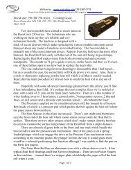
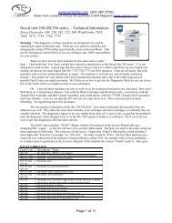
Xerox Docucolor 240, <strong>250</strong>, 242, 252, 260, WorkCentre 7655,<br />
7665, 7675, 7755, 7765, 7775<br />
Warning : <strong>The</strong> diagnostics on these machines are designed to be used by<br />
experienced copier technicians only. <strong>The</strong>se are very sensitive machines and<br />
changing the wrong NVM setting can potentially cause serious problems. Only<br />
use the information which follows if you are willing to take 100% responsibility<br />
for your actions.<br />
When we dove into the fuser modules for this same series a while<br />
back… I had noted that “few Xerox models have earned as much praise as the <strong>DocuColor</strong> <strong>250</strong> series”. I’ve not<br />
changed my mind on that. A good sign that this series is here to stay for a while is that there are new models just<br />
coming out that use the same engine (the WC 7755/7765/7775 are 2010 releases). <strong>The</strong>se are all sturdy, full color<br />
machines with very few inherent problems to report. <strong>The</strong> machine is well laid out, and extremely technician<br />
friendly. This month, let’s get started with a brief introduction and then take a dip in the rather large pool of<br />
possible Fault Codes you might encounter. We’ll also cover how to get into the Diagnostic Mode so you can clear a<br />
few of the Faults which you might run into in your adventures.<br />
Ok… I am told these machines are easy to work on as far as physical mechanics are concerned. How easy?<br />
Well there are 3 maintenance drawers. One with the Drum Cartridges and Developer units, a second one with the<br />
Transfer Belt Assembly and Belt Cleaner Assembly, and a third drawer with the 2 nd BTR (Transfer Roll Assembly)<br />
and Fuser Module. A novice can take the DV Unit out if it came down to it. This is unusual and extremely<br />
refreshing. An engineering marvel by all means.<br />
<strong>The</strong> two groups of machines within this “DC<strong>250</strong> <strong>style</strong>”, have many similarities but naturally there are<br />
differences as well. <strong>The</strong>y share the same fuser modules, toner cartridges and drum cartridges, so internally they are<br />
virtually identical. <strong>The</strong> diagnostics appear to be very similar from what we’ve seen so far, except that the method to<br />
enter the diagnostic mode changed early on in the WC-7655 group of models (v2 software). We’ll cover the two<br />
ways to get into diagnostics after the fault code list.<br />
<strong>The</strong> Fault Codes and their “RAPs” (Repair Analysis Procedures) in the Service Manual take up a<br />
whopping 900 + pages… so this list will have to be severely abbreviated. <strong>The</strong> plan is to stick to the codes which are<br />
more important to field techs. <strong>The</strong> codes are all laid out as 3 digits (the “Chain”) followed by a dash and then 3<br />
more digits (the “Function”) (example: for ‘010-330’… the chain would be ‘010’). <strong>The</strong> first three digits do give<br />
some hint as to which part of the machine is being reffered to (chain ‘010’ for example refers to fuser problems) …<br />
so it makes sense to generalize in the list as to what part of the machine the various “Chains” point to. Here goes:<br />
FAULT CODE LIST:<br />
Fault Code: Description / Notes:<br />
002-770 <strong>The</strong> Hard Drive (HDD) is over capacity<br />
003-xxx codes Generally: Communication Errors between boards in the machine<br />
005-xxx codes Generally: Document Feeder problems<br />
005-121 thru Document Jams<br />
005-158<br />
005-194 thru Document size mismatch problems<br />
005-199<br />
005-275/280 Document Feeder communication errors<br />
005-281 thru Document Tray lift problems<br />
005-283<br />
005-284 Document APS (Automatic Paper Sensors) failure (there are 3 sensors<br />
which detect various paper widths on the document feeder)<br />
005-285 Document Nudger up failure<br />
005-286 Document feed-out sensor failure<br />
005-303 Document Tray Interlock is open<br />
005-304 Document Platen Interlock opened during a job<br />
005-305 Document Top Cover Interlock opened during a job<br />
005-306 Document Tray Interlock opened during a job<br />
Page 1 of 16
www.partsdrop.com (201-387-7776)<br />
Drawn from a series of Articles first published in ENX Magazine (www.enxmag.com)<br />
005-308/309 Document Left Cover is open or opened during a job<br />
005-906 thru Document is still detected in feeder after power-on or after closing one<br />
005-918 of the document door interlocks<br />
010-xxx codes Generally: Fuser faults<br />
010-311 Open fuser thermistor was detected (white connector)<br />
010-319 * Fuser Heat Control problem… *NOTE: This code must be cleared<br />
from Diagnostic Mode… details below.<br />
010-320 ** Fuser Overheat problem… (can be reported by any of the 3<br />
thermistors in the fuser) ** NOTE: This code must be cleared from<br />
Diagnostic Mode… details below.<br />
010-322 thru Fuser thermistor open circuit detected (NC Center Sensor or Rear<br />
010-323 <strong>The</strong>rmistor)<br />
010-324*** Fuser NVM (Memory) failure *** NOTE: This code must be cleared<br />
from Diagnostic Mode… details below.<br />
010-326 thru Fuser Heat Control problems<br />
010-327<br />
010-330 Fuser Motor failure<br />
010-420 Fuser Module nearing end of life... NOTE: Read below for fuser<br />
count reset info.<br />
010-421 Fuser Module “End of Life”… NOTE: if the fuser is still good, you<br />
can replace the Fuser Reset Fuse (on top of the fuser) and possibly the<br />
Fuser Heat Roll to keep it running.<br />
012-xxx codes Generally: Finisher problems<br />
013-xxx codes Generally: Finisher / Booklet Maker problems<br />
016-xxx codes Generally: Options or Software failures<br />
016-311 Scanner not detected<br />
024-340 thru ESS (Network Controller) problems<br />
024-747<br />
024-910 thru Paper size Sensing problems (in one of the paper drawers)<br />
024-917<br />
024-919 Face Up Tray interlock open<br />
024-920/922 Face Down Tray 1 full / Face Down Tray 2 full<br />
024-923/924/ Toner Cartridge Empty – Y / M / C<br />
925<br />
024-927/930 OCT (Offset Catch Tray) full / Stacker Tray full<br />
024-934 thru Paper type mismatch errors<br />
024-939<br />
024-946/947/ Tray not in position (T1/2/3/4)<br />
948/949<br />
024-950/951/ No Paper in tray (T1/2/3/4/5/6/7)<br />
952/953/954/<br />
955/956<br />
042-313 Rear Fuser Cooling Fan failure<br />
042-320/321/ Drum Motor failures – 320=Y, 321=C, 322=M, 323=K (black)<br />
322/323<br />
042-324 IBT Belt Drive Motor failure<br />
042-325 Main Motor failure<br />
042-326 IBT Belt Home position not detected in time ****<br />
042-327 IBT Belt Position failure<br />
042-328 IBT Belt Edge Sensor failure<br />
042-330 Fuser Exhaust Fan failure<br />
042-331 Blower Motor Fan failure<br />
042-600/601/ Belt Edge timing failures<br />
602<br />
042-603 Suction Filter end of life<br />
045-xxx codes Printing communication failures<br />
061-320/321 ROS (Laser Unit) polygon motor failures<br />
061-323 thru ROS (Laser Unit) problems<br />
061-607<br />
062-357 CCD (Scanner) Fan failure<br />
062-360 Exposure Carriage position failure.<br />
062-371 Exposure Lamp not lighting (or very dim)<br />
071-101 thru Paper Jams from Tray 1 at takeaway or registration<br />
071-105<br />
071-210 Tray 1 Lift failure<br />
072-101 thru Paper jams from Tray 2 at takeaway or registration<br />
Page 2 of 16
www.partsdrop.com (201-387-7776)<br />
Drawn from a series of Articles first published in ENX Magazine (www.enxmag.com)<br />
072-105<br />
072-210 Tray 2 Lift failure<br />
073-101 thru Paper jam from Tray 3 at takeaway or registration<br />
073-105<br />
073-210 Tray 3 Lift failure<br />
074-101 thru Paper jam from Tray 4 at takeaway or registration<br />
074-105<br />
074-210 Tray 4 Lift failure<br />
075-100 thru Paper jam from Tray 5 at takeaway or registration<br />
075-135<br />
075-210/211 Tray 5 Lift failure / Lift down failure<br />
077-103 thru Fuser Exit Sensor jam or final Exit Sensor jam.<br />
077-118<br />
077-120 Post 2 nd BTR Roll Sensor jam<br />
077-123 thru Inverter jams<br />
077-130<br />
077-300 Front Cover interlock open<br />
077-301 Left Door interlock open<br />
077-302 Right Cover interlock open<br />
077-303 Transfer Module 2 interlock open<br />
077-909 Paper detected in paper path at power-on<br />
078-100 thru<br />
078-151<br />
Paper jam from Tray 6 / High Capacity Feeder (HCF) at takeaway or<br />
registration<br />
078-<strong>250</strong> Tray 6 (HCF) Lift failure<br />
078-300 HCF (Hi Capacity Feeder) Top Cover interlock open<br />
078-301 HCF Docking Interlock open<br />
089-600 thru Image Registration Control problems<br />
089-617<br />
091-311 BCR and Black Charge Corotron Cleaner control problem<br />
091-312 Black Charge / Preclean HVPS (Hi Volt Power Supply) failure<br />
091-313 Drum Cartridge CRUM (chip) communication failure<br />
091-320 Black Charge Corona Wire is broken<br />
091-400 Waste Toner Bottle replacement needed soon<br />
091-401 Black Drum Cartridge near end of life<br />
091-403 Black Charge Corotron Assembly near end of life<br />
091-404 Black Charge Corotron Assembly has reached end of life<br />
091-411 Yellow Drum Cartridge near end of life<br />
091-421 Magenta Drum Cartridge near end of life<br />
091-431 Cyan Drum Cartridge near end of life<br />
091-910 Waste Toner Bottle not detected<br />
091-911 Waste Toner Bottle full<br />
091-913 Black Drum Cartridge at end of life<br />
091-914 thru Black Drum Cartridge CRUM communication problems<br />
091-916 or<br />
091-921<br />
091-917/920/ Yellow Drum Cartridge CRUM communication problems<br />
924/925/927<br />
091-918/922/ Magenta Drum Cartridge CRUM communication problems<br />
928<br />
091-919/923/ Cyan Drum Cartridge CRUM communication problems<br />
926/929<br />
091-932 Yellow Drum Cartridge end of life<br />
091-933 Magenta Drum Cartridge end of life<br />
091-934 Cyan Drum Cartridge end of life<br />
092-649/650 ADC Sensor Shutter failures<br />
092-651/652 IBT Belt ADC Sensor (MOB ADC) failures<br />
092-653 thru<br />
092-660<br />
ATC (from Developer Unit) problems…<br />
653/657=yellow, 654/658=magenta, 655/659=cyan, 656/660=black<br />
093-300 Marking Drawer Interlock open<br />
093-313 thru Toner Dispense problems… 314=Y, 315=M, 316=C, 317=K (black)<br />
093-317<br />
093-320 Developer Motor failure<br />
093-421 thru Toner Cartridges low 421/422=K(black), 423=Y, 424=M, 425=C<br />
093-425<br />
093-600 thru<br />
093-912<br />
Toner Dispense problems (600=Y, 601=M, 602=C,<br />
603/912=K(Black),<br />
093-918 thru Toner CRUM failures (918/924/925/926/936/940=K(black),<br />
Page 3 of 16
www.partsdrop.com (201-387-7776)<br />
Drawn from a series of Articles first published in ENX Magazine (www.enxmag.com)<br />
093-940 927/933/937=Y, 928/934/938=M, 929/935/939=C<br />
094-320/321 1 st BTR (Transfer Roll) retract or contact problems<br />
094-322/323 2 nd BTR (Transfer Roll) retract or contact problems<br />
102-xxx codes Generally: Network Controller (ESS) problems<br />
112-700 Finisher Punch Dust Box full (hole punch bin)<br />
116-xxx codes Generally: Network Controller (ESS) problems<br />
123-xxx codes Generally: UI (control panel) faults<br />
124-xxx codes Generally: Configuration errors (example: serial number disagreement<br />
between various boards… or machine speed errors, etc)<br />
127-xxx codes<br />
Printing failures<br />
Clearing some fault codes (from Diagnostics):<br />
*Fuser Heat Control problems (010-319)… Read below about how to reset NVM value 744-351 back to ‘0’.<br />
**Fuser Overheat problems (010-320)… Read below about how to reset NVM value 744-350 back to ‘0’.<br />
***Fuser NVM (memory) failure (010-324)… Read below about how to reset NVM value 744-352 back to ‘0’.<br />
****IBT Belt Home Position Sensor Failure (043-326)… Read below about how to reset NVM value 741-105 to ‘0’<br />
Warning : <strong>The</strong> diagnostics on these machines are designed to be used by experienced copier technicians only.<br />
<strong>The</strong>se are very sensitive machines and changing the wrong NVM setting can potentially cause serious problems.<br />
Only use the information which follows if you are willing to take 100% responsibility for your actions.<br />
1. Diagnostic Entry: For DC240/242/<strong>250</strong>/252/260: Hold down the ‘0’ button for 5 full seconds and then while<br />
still holding the ‘0’, press ‘Start’. A prompt for a password will show up (the “CE Access Number”). Use the<br />
default password ‘6789’, and press ‘Confirm’.<br />
For most WC-7655/7665/7675’s (some of them with earlier software work like the DC<strong>250</strong> above): Hold<br />
down together ‘*’, ‘#’, & ‘Stop’ until the “CE Access Number” screen prompts you for a password. <strong>The</strong>n use<br />
the default password: ‘6789’ followed by ‘Confirm’.<br />
2. Press the “Log-in / Log-out” button… then on the touchscreen, touch “System Settings”, followed by<br />
“Common Settings”, and finally “Maintenance / Diagnostics”.<br />
3. Choose “Adjustments” from the menu which appears, then look for: “Dc131 NVM Read / Write”.<br />
4. Touch the first empty block to enter the “chain” 744. <strong>The</strong> 1 st three digits in an NVM code are called the “chain”<br />
and the second set of 3 digits are called the “Function”. Enter the appropriate “Function” code (351 for Fault<br />
Code 010-319, 156 for Fault Code 010-320, or 352 for Fault Code 010-324). Touch the “Read” button. <strong>The</strong><br />
current setting will show up. Press “Val” to then change the value back to ‘0’ and press ‘Save’.<br />
5. Finally when you exit diagnostics be sure to reboot the machine so the changes stick. Use the “Call Close”<br />
button.<br />
<strong>The</strong> “Machine Status” Button:<br />
<strong>The</strong> “Machine Status” button near the lower left of the control panel gives folks access to the following stuff:<br />
• Machine Information (includes serial number, machine configuration, a paper tray status chart, & software versions)<br />
• Billing Meters<br />
• Print Report / List (basic reports like job status, copy mode settings, print mode settings, or scan mode settings)<br />
• Consumables (a list of customer replaceable consumables and their status)<br />
While the current fault code or message is normally displayed on the upper left corner of the screen, you<br />
may want to also view a Fault History Report to see what faults have been going on lately. This can be done by<br />
pressing the “Machine Status” button. <strong>The</strong>n touch the “Faults” tab. A button will show up which will allow you to<br />
print out the “Fault History Report”…<br />
System Administrator Mode:<br />
This password protected mode allows the key operator or administrator more access to things like default settings.<br />
To get into System Administrator Mode:<br />
For DC240/242/<strong>250</strong>/252/260: Press “Log-in/out” and enter the password (the default is ‘11111’ (five 1’s)).<br />
For WC-7655/7665/7675: Press “Log-in/out” and enter a user name “admin” followed by the password (the default<br />
is ‘1111’ (four 1’s)). If the default password does not work, you’ll need to ask the customer for the new password.<br />
Once you’re in the System Administrator mode, you’ll see a menu with 4 choices:<br />
• System Settings (This choice’s submenu is covered below)<br />
• Setup Menu (Paper Tray Attributes settings)<br />
• System Administrator Settings (Login ID, Administrator Password, & Maximum Login Attempts)<br />
• Login Setup / Auditron Administration<br />
Page 4 of 16
www.partsdrop.com (201-387-7776)<br />
Drawn from a series of Articles first published in ENX Magazine (www.enxmag.com)<br />
System Settings brings you to a submenu: Common Settings, Copy Mode Settings, Scan Mode Settings, &<br />
Network Controller Settings.<br />
If you choose “Common Settings” you’ll see a nice long list of choices:<br />
• Machine Clock / Timers<br />
• Audio Tones<br />
• Screen Defaults<br />
• Paper Tray Settings<br />
• Image Quality Adjustments<br />
• Reports<br />
• Maintenance / Diagnostics (in System Admin Mode, two choices appear: “Initialize Hard Drive”, or “Delete All<br />
Data”, you’ll see later that this submenu has a much wider range of choices from “CE” mode / UI Diagnostic Mode.)<br />
• Watermark<br />
• Other Settings<br />
DIAGNOSTICS<br />
UI (User Interface) Diagnostic Mode (also called “CE Mode”):<br />
CAUTION: I think it is very important to caution anyone who might read this, that the UI Diagnostic Mode is for<br />
experienced technicians … changing settings or running internal tests on these machines without an in-depth<br />
understanding of what you are doing can cause serious problems or even damage to the machine, and can also be<br />
dangerous for the person running the tests. Do not use the information presented here unless you are willing to<br />
take 100% responsibility for your actions.<br />
<strong>The</strong> process for getting into the UI Diagnostic Mode depends on exactly which model you’re working on.<br />
For DC240/242/<strong>250</strong>/252/260: Hold down the ‘0’ button for 5 full seconds and then, while still holding the ‘0’,<br />
press ‘Start’. A prompt for a password will show up (the “CE Access Number” screen). Use the default password<br />
‘6789’ followed by ‘Confirm’. Next press the “Log-in / Log-out’ button.<br />
For most WC-7655/7665/7675’s (some early ones work like the DC<strong>250</strong> above… also probably true for the<br />
7755/7765/7775): Hold down together ‘*’, ‘#’, & ‘Stop’ until the password prompt shows up. <strong>The</strong>n use the ‘6789’<br />
default password followed by ‘Confirm’. Next press the “Log-in / Log-out’ button.<br />
Once you’re in UI Diagnostic Mode, choose ‘System Settings’, then choose ‘Common Settings’, followed<br />
by ‘Maintenance / Diagnostics’. Here you’ll find the most important menu… We’ll talk briefly about each of the<br />
menu items afterwards. Here are the things you’ll see:<br />
• Software Options (Allows an OEM rep to install upgrades for the machine using passwords provided by the OEM using the<br />
machine’s serial number to generate the password. If a machine has options installed, make sure to keep a backup of all any<br />
passwords for that machine’s options. )<br />
• Print Test Patterns<br />
• MAX Setup (for color registration setup, etc.)<br />
• Initialize Hard Disk (Warning… Don’t use this without a full understanding of what the procedure will do… you’ll need to have<br />
the full Service Manual on-hand. This will reformat partition 1… eliminating all fonts & Job Templates)<br />
• NVM Intialization (Warning… Don’t use this one either without a full understanding of what the procedure will do… you should<br />
only use this stuff if you have the full Service Manual with you.)<br />
• IO Check (Component Control… allows you to test Input & Output Components… you will need a list of what each<br />
Component’s Control Code is to use this)<br />
• Sub System (has a sub menu choice: “Belt Edge Learn…” necessary for whenever the IBT Belt is replaced)<br />
• Delete All Data<br />
• NVM Read/Write (allows you to change NVM [Non Volatile Memory] settings… you will need a list of what each NVM Setting<br />
Code is before you can make use of this.)<br />
• Registration (Registration of the image on the paper… read more below)<br />
• Adjustment / Others (has a sub menu with two choices: “Machine ID / Billing Data Settings” & “Initialize HFSI Counter”)<br />
This is a fair range of access. Don’t get me wrong… the authorized dealers who have the PWS Laptops<br />
(the Portable work Station) do maintain some significant advantages. <strong>The</strong> main limitation you face without a PWS<br />
(Portable Work Station), is that in “Component Control” and also in “NVM / Read Write” (memory settings), you<br />
Page 5 of 16
www.partsdrop.com (201-387-7776)<br />
Drawn from a series of Articles first published in ENX Magazine (www.enxmag.com)<br />
can’t browse through a list of codes to choose from. For these two functions, you’ll need to know which code you<br />
are going to enter, so you’ll be needing lists of these codes. <strong>The</strong>se lists are only viewable from the PWS’s screen.<br />
Now lets have a more in-depth look at each of the menu choices from the list above:<br />
Software Options: If you press “Software Options” followed by “Keyboard”, you can then punch in the password<br />
for the optional service you are installing or re-installing… then select ‘Save’ followed by ‘Reboot’.<br />
Print Test Patterns: <strong>The</strong>re are many available test patterns which are useful for troubleshooting copy quality<br />
problems and for isolating which board may be responsible for the symptom you are troubleshooting. <strong>The</strong>re are a<br />
wide range of patterns to choose from…Each has its own 3 digit code. It appears that the list will not show up onscreen…<br />
so, you will need a list of the pattern’s 3 digit codes or else you’d be choosing blindly.<br />
Pattern # Test Pattern Name Source<br />
001 Registration Grid MCU PWB<br />
002 Grid 45 Degree MCU PWB<br />
003 Color Registration MCU PWB<br />
004 Color Registration -Visual MCU PWB<br />
005 Banding MCU PWB<br />
006 Ted/starvation MCU PWB<br />
007 Automatic Tone Correction -Adjustment MCU PWB<br />
008 Automatic Tone Correction -Check MCU PWB<br />
009 ProCon MCU PWB<br />
010 16 tone MCU PWB<br />
011 Halftone MCU PWB<br />
012 In/out Adjustment (Primary Colors) MCU PWB<br />
013 In/out Adjustment (Secondary Colors) MCU PWB<br />
014 In/out Adjustment (Single Color) MCU PWB<br />
015 Highlight Adjustment MCU PWB<br />
016 Color Patch 182 MCU PWB<br />
017 Gradation MCU PWB<br />
018 Adjustment in SS direction_YC MCU PWB<br />
019 Adjustment in SS direction_MK MCU PWB<br />
110 IIT Analog Gradation RGB IIT/IPS PWB<br />
112 IIT Analog Gradation BW IIT/IPS PWB<br />
113 Pre-IPS_FS Increment RGB IIT/IPS PWB<br />
115 Pre-IPS_FS Increment BW IIT/IPS PWB<br />
117 Pre-IPS_SS Increment RGB IIT/IPS PWB<br />
119 Pre-IPS_SS Increment BW IIT/IPS PWB<br />
121 Pre-IPS_Grid BW IIT/IPS PWB<br />
122 Pre-IPS_Shading Data Color IIT/IPS PWB<br />
123 Pre-IPS_Shading Data BW IIT/IPS PWB<br />
124 Pre-IPS_Vertical Stripes IIT/IPS PWB<br />
125 Pre-IPS_8 Tone Patch IIT/IPS PWB<br />
126 Pre-IPS_Solid IIT/IPS PWB<br />
127 Post-IPS 4C IIT/IPS PWB<br />
128 Post-IPS_BW IIT/IPS PWB<br />
129 Post-IPS_FSRE Grid IIT/IPS PWB<br />
130 Post-IPS_FSRE Diagonal Grid IIT/IPS PWB<br />
131 Post-IPS_Bit Pattern 2 Level BW IIT/IPS PWB<br />
132 Post-IPS_Bit Pattern 2 Level 4C IIT/IPS PWB<br />
133 Post-IPS_Bit Pattern Multi-level BW IIT/IPS PWB<br />
134 Post-IPS_Bit Pattern Multi-level 4C IIT/IPS PWB<br />
135 TAG Fixed Copy 1 IIT/IPS PWB<br />
137 Pre-IPS_FS Increment (Ext Bypss) IIT/IPS PWB<br />
138 Pre-IPS_SS increment (Ext bypass) IIT/IPS PWB<br />
139 Pre-IPS_Vertical Stripes (Ext Bypass) IIT/IPS PWB<br />
140 Pre-IPS_FS increment (via Ext Mem. PWB) IIT/IPS PWB<br />
141 Pre-IPS_SS increment (via Ext Mem. PWB) IIT/IPS PWB<br />
142 Pre-IPS_Vertical Stripes (via Ext. Mem. PWB) IIT/IPS PWB<br />
MAX Setup: <strong>The</strong> MAX setup menu contains the following stuff:<br />
• Procon ON/OFF Print<br />
• IIT Calibration<br />
• In/Out Manual Setup<br />
• ATC Sensor Setup<br />
• TRC Adjust<br />
• Tone Up/Down<br />
• Color Balance<br />
Page 6 of 16
www.partsdrop.com (201-387-7776)<br />
Drawn from a series of Articles first published in ENX Magazine (www.enxmag.com)<br />
Component Control: Here is where you’ll go to test Input Components such as Sensors and Switches… and also<br />
Output Components such as motors, solenoids, lamps, & clutches. You will be needing the list of codes and their<br />
corresponding components to use this at all since it does not appear in a menu on the Control Panel. We’ll cover the<br />
list in an abbreviated fashion in the next article. It is a very lengthy list.<br />
Delete All Data:<br />
To quote the Service Manual: “This procedure deletes user-defined/registered information and information recorded<br />
automatically by the system from the hard disk, the ESS NVM PWB and Buffer RAM”.<br />
NVM Read / Write:<br />
This will need to be covered in a future article because the lists of NVM codes are not browse-able from the Control<br />
Panel. <strong>The</strong> list is very long. Until the list is available, you won’t be able to change any NVM Settings (you’d be<br />
working totally blind).<br />
Machine ID / Billing Data Settings<br />
<strong>The</strong>re are 3 boards in the machine which all have the Serial Number, Product Number and Billing Counters: the<br />
MCU NVM PWB (the IOT or Main machine logic board), the SEEP ROM (on the ESS or Network Controller,<br />
known as Sys1), and the ESS NVM PWB (sys2 on the ESS or Network Controller). <strong>The</strong>se 3 must agree with each<br />
other (otherwise a Fault Code will be called… 124-310, 124-311, 124-312, 124-313, 124-324, or 124-325). This<br />
process is designed to synchronize the three boards when one of them gets corrupted or needs to be replaced. From<br />
“Machine ID / Billing Data Settings”, choose a Board which has the correct data on it and select ‘Start’… Enter the<br />
correct Serial Number and then select ‘Confirm’.<br />
In Part II of this series, we got into the Diagnostic Mode (“CE Mode”). Lots of good stuff in there, but to<br />
use the Component Codes to test motors, sensor, etc, you need to know what each code is. In this month’s article,<br />
we’ll begin to list ‘em… starting with the Input Component Codes. It makes for rather bland reading, but it is one of<br />
the keys to being able to troubleshoot & solve problems on these machines… so here goes.<br />
Component Control<br />
Once you’re in UI Diagnostic Mode, choose ‘System Settings’, then choose ‘Common Settings’, followed<br />
by ‘Maintenance / Diagnostics’. Scroll down and choose “IO Check” & finally select: “Component Control”.<br />
From the Component Control screen, you’ll enter the “Chain” (the first 3 digits of the code) followed by<br />
the “Function” (the second 3 digits of the code). Press ‘Start’ to activate the test. For these Input Component<br />
Tests, you will be able to see on-screen the status of the component (H for high or L for low)… you can toggle the<br />
actuator or otherwise activate the switch or sensor you’re trying out and see if the status of the component changes<br />
on-screen. Press ‘Stop’ button to stop the current test. When you’re done, press ‘Close’ to leave the Component<br />
Control screen.<br />
Below is an abbreviated list of the component codes. <strong>The</strong>re were simply too many codes to include in a<br />
magazine article. <strong>The</strong> ones which are missing were either relating to peripherals such as the finishers, or the<br />
description for the comoponent was too ambiguous to be of use. <strong>The</strong> list is followed by a quick run-down of what<br />
some of the acronyms stand for.<br />
Page 7 of 16
www.partsdrop.com (201-387-7776)<br />
Drawn from a series of Articles first published in ENX Magazine (www.enxmag.com)<br />
Input Component Codes:<br />
Code Description<br />
005-102 Document Sensor<br />
Document Regi Sensor _ Belt DADF and<br />
005-110 CVT<br />
005-115 Document Exit Sensor<br />
005-119 Document Duplex Sensor<br />
005-150 Document Size Sensor #1<br />
005-151 Document Size Sensor #2<br />
005-202 Document Feeder Bottom Sensor<br />
005-203 Document Feeder Level Sensor<br />
005-204 Document Feeder Feed Sensor<br />
005-205 Document Feed-out Sensor<br />
005-206 Document Pre-registration Sensor<br />
005-207 Document Lead Registration Sensor<br />
005-208 Document out Sensor<br />
005-209 Document Exit Sensor #1<br />
005-210 Document Exit Sensor #2<br />
005-211 Document Invert Sensor<br />
005-212 Feeder Cover Interlock Switch<br />
005-213 Document Feeder Platen Interlock Switch<br />
005-214 Document Tray Interlock Sensor<br />
005-215 DADF #1 tray APS sensor<br />
005-216 DADF #2 tray APS sensor<br />
005-217 DADF #3 tray APS sensor<br />
005-218 DADF #1 APS sensor<br />
005-219 DADF #2 APS sensor<br />
005-220 DADF#3 APS sensor<br />
005-221 DADF tray size sensor #1<br />
005-222 DADF tray size sensor #2<br />
005-223 DADF Left hand cover interlock switch<br />
005-224 DADF Scan start Sensor<br />
005-225 DADF Nudger position sensor<br />
005-226 DADF #2 invert sensor<br />
005-300 DADF Platen interlock switch<br />
005-301 DADF Top cover interlock switch<br />
010-200 Fuser entrance sensor<br />
010-201 Fuser exit sensor<br />
010-202 Detection of a new fuser CRU<br />
010-203 Fuser nip sensor<br />
014-100 Xport entrance sensor<br />
014-101 Buffer path sensor<br />
014-102 Gate sensor<br />
014-110 Registration clutch on<br />
014-111 IOT exit sensor<br />
014-115 Top exit tray sensor<br />
014-150 Compile exit sensor<br />
014-151 Compile tray no paper sensor<br />
014-190 Decurler-in sensor<br />
014-191 Decurler-out sensor<br />
014-200 Side registration sensor_1<br />
014-201 Side registration sensor_2<br />
061-200 Polygon motor 1 ready<br />
061-201 Polygon motor 2 ready<br />
062-212 IIT (scan) registration sensor<br />
062-240 DADF present<br />
062-251 APS sensor 1<br />
062-253 APS sensor 2<br />
062-272 Scan start<br />
062-300 Platen interlock switch<br />
062-301 Angle sensor<br />
071-100 Tray 1 pre feed sensor<br />
071-101 Feed out sensor 1<br />
071-200 Tray 1 stack height sensor<br />
071-201 Tray 1 no paper sensor<br />
071-202 Tray 1 size select<br />
072-100 Tray 2 pre feed sensor<br />
072-101 Feed out sensor 2<br />
072-200 Tray 2 stack height sensor<br />
072-201 Tray 2 no paper sensor<br />
072-202 Tray 2 size select<br />
073-100 Tray 3 pre feed sensor<br />
073-101 Feed out sensor 3<br />
073-200 Tray 3 stack height sensor<br />
073-201 Tray 3 no paper sensor<br />
074-100 Tray 4 pre feed sensor<br />
074-101 Feed out sensor 4<br />
074-200 Tray 4 stack height sensor<br />
074-201 Tray 4 no paper sensor<br />
075-100 MSI (bypass) pre feed sensor<br />
Page 8 of 16
www.partsdrop.com (201-387-7776)<br />
Drawn from a series of Articles first published in ENX Magazine (www.enxmag.com)<br />
075-200 MSI (bypass) stack height sensor<br />
075-201 MSI (bypass) lift down sensor<br />
075-202 MSI (bypass) no paper sensor<br />
075-203 MSI (bypass) paper set sensor<br />
077-100 Pre registration sensor<br />
077-101 Registration sensor<br />
077-102 OHP (transparency) sensor<br />
077-103 Invert in sensor<br />
077-104 Duplex in sensor<br />
077-105 Duplex path sensor<br />
077-106 Duplex out sensor<br />
077-107 IOT exit sensor<br />
077-108 MSI pre regi sensor<br />
077-203 Invert End sensor<br />
077-300 Left hand cover interlock<br />
077-301 Right hand cover interlock<br />
077-302 Transfer module 2 interlock<br />
077-303 Front cover interlock<br />
077-304 MSI (bypass) cover interlock<br />
078-100 HCF (Hi Capacity Feeder) 1 pre feed sensor<br />
078-101 HCF 1 feed out sensor<br />
078-200 HCF 1 no paper sensor<br />
078-201 HCF 1 stack height sensor<br />
078-202 HCF 1 size sensor A<br />
078-203 HCF 1 size sensor B<br />
078-204 HCF 1 tray in sensor<br />
078-300 HCF 1 transport interlock<br />
078-301 HCF 1 side out switch<br />
091-200 Waste toner bottle present sensor<br />
091-201 Waste toner bottle near full sensor<br />
091-202 Charge Scorotron fuse current signal<br />
093-200 Low toner sensor Y<br />
093-201 Low toner sensor M<br />
093-202 Low toner sensor C<br />
093-203 Low toner sensor K<br />
093-205 Dispense cover sensor<br />
093-206 Marking drawer interlock<br />
094-200 1st BTR retract sensor<br />
094-201 2nd BTR retract sensor<br />
094-202 Post 2nd BTR sensor<br />
Acronym interpretations:<br />
BCR = Bias Charge Roll (from color drum ctg)<br />
BTR = Bias Transfer Roll<br />
CC = charge Corona (on black drum cartridge)<br />
CCD = Charge Coupled Device (turns image into<br />
CVT = Constant Velocity Transport<br />
DADF = Duplexing Automatic Document Feeder<br />
HCF = High Capacity Feeder<br />
IBT = Image Belt Transfer<br />
IIT = Image Input Terminal (scanning section of machine)<br />
IOT = Image Output Termimal (printing section of<br />
machine)<br />
IPS = Image Processing<br />
J- tra = ‘J’ Transport<br />
MOB = Marks On Belt<br />
MSI = Multiple Size Input (Bypass Tray)<br />
OCT = Oscillating Catch Tray<br />
V-tra = Vertical Transport<br />
Output Component Codes:<br />
Code<br />
005-001<br />
Thru<br />
005-010<br />
Description<br />
CVT - DADF feed motor _ speed 1 thru 10<br />
005-011 Document Set gate solenoid open<br />
005-012 Document Set gate solenoid close<br />
005-014 CVT - DADF feed motor _ reverse<br />
005-015<br />
Thru CVT - DADF pre reg motor _ speed 1 thru 11<br />
005-025<br />
005-026<br />
thru CVT - DADF reg motor _ speed 1 thru 10<br />
005-035<br />
005-036 CVT - DADF reg motor _ reverse<br />
005-037<br />
038/039 CVT - DADF platen motor _ speed 1/2/3<br />
005-040 DADF feed motor<br />
005-041<br />
Thru CVT - DADF platen motor _ speed 4 thru 10<br />
005-047<br />
005-048<br />
Thru CVT - DADF exit motor _ speed 1 thru 7<br />
005-054<br />
005-055 Document Belt motor non CVT mode_CW<br />
005-057<br />
Thru CVT - DADF exit motor _ speed 8 thru 12<br />
005-061<br />
005-062 CVT - DADF feed clutch<br />
005-063 Document Nudger solenoid down<br />
005-065 Document Baffle solenoid close<br />
005-067 Simplex/duplex gate solenoid duplex open<br />
005-068 Simplex/duplex gate solenoid simplex open<br />
005-069 Document Exit gate solenoid<br />
Page 9 of 16
www.partsdrop.com (201-387-7776)<br />
Drawn from a series of Articles first published in ENX Magazine (www.enxmag.com)<br />
005-070 Document Nip release solenoid_PF1<br />
005-073 CVT-DADF stamp solenoid<br />
005-074 CVT-DADF feed motor<br />
005-075 Regi gate solenoid<br />
005-081 Exit motor non CVT mode<br />
005-083 Document ready<br />
005-084 Document set LED<br />
005-086 Document Tray lift up<br />
005-090 Document Nudger initialize<br />
010-001 Fuser motor _ 320 mm/s<br />
010-007 Heat roll main lamp 1<br />
010-008 Heat roll main lamp 2<br />
010-009 Heat roll sub lamp<br />
042-001 Main motor_320 mm/s<br />
042-005 Drum motor K_320 mm/s<br />
042-009 Drum motor YMC_220 mm/s<br />
042-012 IBT drive motor_320 mm/s<br />
042-016 IBT steering motor (CW) High current<br />
042-018 IBT steering motor (CW) Low current<br />
042-020 Fuser exhaust fan_high speed<br />
042-021 Blower motor_high speed<br />
042-023 CC intake fan_high speed<br />
042-026 V_tra fan_high speed<br />
042-028 Invert front fan and dup fan<br />
042-029 Exit roll fans<br />
042-030 IBT Belt check_320 mm/s<br />
042-034 Rear cooling fan<br />
042-035 IBT steering motor reset<br />
061-001 Polygon motor 1_high speed<br />
061-004 Polygon motor 2_low speed<br />
061-005 LASER 1_high speed<br />
061-007 LASER 2_high speed<br />
062-002 IIT exposure lamp<br />
062-005 IIT scan motor_scan direction<br />
062-006 IIT scan motor_return direction<br />
062-014 IPS cooling fan_high speed_PF1<br />
062-015 Lamp cooling fan_PF1<br />
062-017 Ccd cooling fan<br />
062-086 IIT image area<br />
071-001 Tray 1 pre feed<br />
071-002 Tray 1 feed<br />
071-004 Tray 1 lift up<br />
072-001 Tray 2 feed<br />
072-002 Tray 2 lift up<br />
073-001 Tray 3 feed<br />
073-002 Tray 3 lift up<br />
074-001 Tray 4 feed<br />
074-002 Tray 4 lift up<br />
075-001 MSI (bypass) feed motor_300 mm/s<br />
075-002 MSI (bypass) feed motor_220 mm/s<br />
075-003 MSI nudger solenoid_high current<br />
075-004 MSI nudger solenoid_low current<br />
075-005 MSI lift motor up (CW) sensor stop<br />
075-006 MSI lift motor down (CCW) sensor stop<br />
077-001 Take away motor<br />
077-002 Take away clutch 1<br />
077-003 Take away clutch 2<br />
077-004 Pre regi motor_640 mm/sec<br />
077-006 Pre regi motor_220 mm/sec<br />
077-007 Regi motor_430 mm/sec<br />
077-010 Exit motor<br />
077-011 Invert solenoid_gate in<br />
077-012 Invert solenoid_gate exit<br />
077-013 Invert motor_450 mm/s_invert direction<br />
077-014 Invert motor_350 mm/s_exit direction<br />
077-015 Invert motor_640 mm/s_dup path direction<br />
077-016 Invert solenoid<br />
077-018 Duplex motor<br />
077-019 Invert gate In and invert gate exit cycle<br />
078-001 HCF 1 nudger solenoid_low power<br />
078-002 HCF 1 nudger solenoid_high power<br />
078-003 HCF 1 feed motor_feed direction<br />
078-004 HCF 1 feed motor_lift up direction<br />
078-005 HCF 1 Takeaway motor_242 mm/sec<br />
089-001 MOB LED: High power<br />
089-002 MOB LED: Low power<br />
091-001 Erase lamp YMC<br />
091-002 Erase lamp K<br />
091-007 Scorotron<br />
091-008 Pre Charge Corotron (PCC)<br />
Page 10 of 16
091-009<br />
www.partsdrop.com (201-387-7776)<br />
Drawn from a series of Articles first published in ENX Magazine (www.enxmag.com)<br />
BCR Scorotron cleaner mot_1400PPS (CW) hi<br />
current<br />
092-001 ADC specular<br />
092-002 ADC Diffuse<br />
092-004 ADC shutter open<br />
092-005 ADC shutter close<br />
093-001 Toner cartridge motor_Y<br />
093-002 Toner cartridge motor_M<br />
093-003 Toner cartridge motor_C<br />
093-004 Toner cartridge motor_K1<br />
093-005 Toner cartridge motor_K2<br />
093-006 Dispense motor_Y<br />
093-007 Dispense motor_M<br />
093-008 Dispense motor_C<br />
093-009 Dispense motor_K<br />
093-010 Developer bias DC_Y<br />
093-011 Developer bias AC_Y, M, C<br />
093-012 Developer bias DC_M<br />
093-014 Developer bias DC_C<br />
093-016 Developer bias DC_K<br />
093-017 Developer bias AC_K<br />
093-019 Developer motor_220 mm/s<br />
093-022 Developer clutch<br />
Developer K rotation at 220 mm/s process<br />
093-023 speed<br />
Developer YMC rotation at 220 mm/s process<br />
093-024 speed<br />
094-001 1st BTR contact<br />
094-002 1st BTR retract<br />
094-003 2nd BTR contact<br />
094-004 2nd BTR retract<br />
094-005 2nd BTR retract clutch<br />
Page 11 of 16
www.partsdrop.com (201-387-7776)<br />
Drawn from a series of Articles first published in ENX Magazine (www.enxmag.com)<br />
<strong>The</strong>se are friendly to technicians in nearly every way possible. <strong>The</strong> exception as mentioned earlier is that<br />
you actually need to know which 6 digit code you want to run. Even the Service Manual fails to provide lists.<br />
Fortunately if you pick through the RAP’s (repair analysis procedures), the manual does give you suggestions as to<br />
which codes to use to test sensors, motors, etc. <strong>The</strong>y will also usually (not always) tell you if a particular NVM<br />
setting needs to be changed back to “0” to clear the Fault Condition.<br />
As you look through the list, you will find that while some of the codes are useful in very specific<br />
circumstances, the most important ones revolve around resetting specific Fault Code conditions. <strong>The</strong>se Fault<br />
Conditions will not reset automatically… the machine will not even attempt to get going till a related Memory code<br />
is reset. Some are flags which are either 0 or 1 depending on if the fault condition exits or not, and others count up<br />
to 3 at which point the machine shuts down and needs that memory setting to be reset back to “0”.<br />
Extremely important: Part of the reason the machines “lock up” until certain fault codes are cleared is because a<br />
tech needs to come and repair the cause of the fault. It is very unwise to allow a customer to keep running a<br />
machine calling one of these faults, by constantly resetting the codes. That would have the potential to cause more<br />
trouble and possibly damage to the machine. Do not ignore the cause of the fault codes… Always get the problem<br />
solved before you get into resetting things… If you’re the owner of a machine, don’t reset the code… wait for the<br />
technician. Let them fix the problem and then let them reset the fault code.<br />
Here’s how to get into Diagnostic Mode, and how to use “NVM Read / Write”.<br />
6. Diagnostic Entry: For DC240/242/<strong>250</strong>/252/260: Hold down the ‘0’ button for 5 full seconds and then while<br />
still holding the ‘0’, press ‘Start’. A prompt for a password will show up (the “CE Access Number”). Use the<br />
default password ‘6789’, and press ‘Confirm’.<br />
For most WC-7655/7665/7675’s (some of them with earlier software work like the DC<strong>250</strong> above) & also<br />
for WC-7755/7765/7775: Hold down together ‘*’, ‘#’, & ‘Stop’ until the “CE Access Number” screen prompts<br />
you for a password. <strong>The</strong>n use the default password: ‘6789’ followed by ‘Confirm’.<br />
7. Press the “Log-in / Log-out” button… then on the touchscreen, touch “System Settings”, followed by<br />
“Common Settings”, and finally “Maintenance / Diagnostics”.<br />
8. Choose “Adjustments” from the menu which appears, then look for: “Dc131 NVM Read / Write”.<br />
9. Touch the first empty block to enter the “chain”. <strong>The</strong> 1 st three digits in an NVM code are called the “chain” and<br />
the second set of 3 digits are called the “Function”. For example if the NVM code is ‘744-351’ you will enter<br />
the “Chain” as ‘744’ and the “Function” as ‘351’ . Touch the “Read” button. <strong>The</strong> current setting will show up.<br />
Press “Val” to then change the value back to ‘0’ and press ‘Save’.<br />
10. Finally when you exit diagnostics be sure to reboot the machine so the changes stick. Use the “Call Close”<br />
button.<br />
We’ll be leaving a huge number of NVM codes off of the list to follow. Many of the codes you may have thought<br />
you wanted such as registration adjustments are far more effectively managed by using the “Registration” or “Max<br />
Setup” (color registration) choices in the diagnostic menu. Note that where Fault Codes are mentioned, the first<br />
digit will be a “0” if the machine is in the DC family (example 042-326) or it will be a “3” if the machine is a<br />
WorkCentre 76xx (Example: Fault Code 042-326 in a DC<strong>250</strong> will appear instead as 342-326 in a WC-7655).<br />
Ok.. now to it! Here’s the list<br />
NVM (Non Volatile Memory) Codes:<br />
Code Description Min Max Default Details<br />
700-071 USB User Buffer Size 64 1024 64 1 step = 1 Kb, 32 Kb increments<br />
700-078 Form Buffer Size 128 2048 128 1 step = 1 Kb, 32 Kb increments<br />
700-081 Parallel (IEEE 1284) Buffer Size 64 1024 64 1 step = 1 Kb, 32 Kb increments<br />
700-084 NetWare Buffer Size 64 1024 256 1 step = 1 Kb, 32 Kb increments<br />
700-085 Apple Talk Buffer Size 64 1024 64 1 step = 1 Kb, 32 Kb increments<br />
Page 12 of 16
www.partsdrop.com (201-387-7776)<br />
Drawn from a series of Articles first published in ENX Magazine (www.enxmag.com)<br />
700-088 Saturation Buffer Size 64 1024 256 1 step = 1 Kb, 32 Kb increments<br />
700-124 Auto clear and auto resume timer 0 240 60<br />
700-125 Job cancel timer 0 5940 600<br />
700-128 Scanning Timer 1 20 1<br />
700-129 Low Power Mode Timer 1 240 15<br />
700-142 Low Power Mode Enable 0 1 0 0=disabled, 1=enabled<br />
700-143 Job Memory Entry Tone 0 3 2 0=off, 3=loudest<br />
700-144 Auto Log Print Flag 0 1 0 0=off, 1=on<br />
700-145 Report Duplex Print 0 1 0 0=off, 1=on<br />
700-146 Mail Box Receive Report 0 1 1 0=off, 1=on<br />
700-153 Out of Paper Alarm 0 1 1 0=off, 1=on<br />
700-165 Country Code SEEPROM 0 65535 840 840=USA, 124-Canada, 76=Brazil,<br />
826=UK, 276=Germany, 380=Italy,<br />
<strong>250</strong>=France, 724=Spain,<br />
528=Netherlands<br />
700-166 Territory / Region 0 4 0 1=FX , 2=XC (U.S.), 3=XE, 4=AP<br />
700-171 Service Engineer Tools Password 4-12 digits, ASCII<br />
700-197 Max Number of Jobs 90 3000 600<br />
700-198 Job Passing (permitted or not) 0 1 1 0=Not Permitted, 1=Permitted<br />
700-397 Default Print Paper Size 0 255 0 5=A4 (XE default), 44=Letter (XC<br />
default)<br />
700-399 Millimeters vs. Inches 1 3 1 1=mm (XE default), 3=inch (XC<br />
default)<br />
700-420 Software Download Inhibit / Permit 0 1 0 0=Permit, 1=Inhibit<br />
700-446 HDD Security Overwrite Enable 0 1 1 0=disabled, 1=enabled<br />
700-540 Auditron Mode 0 3 0 0=off, 1=Internal Auditron,<br />
2=Network Accounting,<br />
3=Remote/External<br />
700-543 User Information Memory Location 0 1 0 0=NVRAM, 1=HDD<br />
711-297 Communication Fault Bypass 0 1 0 0=Do not bypass Communication<br />
Faults, 1=Bypass (ignore)<br />
communication Faults<br />
715-017 IIT (scanner) Fault Bypass 0 1 0 0=Do not bypass Scanner Faults,<br />
1=Bypass (ignore) Scanner Faults<br />
741-105* Transfer Belt Home Position Fault (Clear<br />
fault 042-326 or 342-326)<br />
0 3 0 0=Fault Clear<br />
741-181 Fuser Exhaust Fan Fault Bypass 0 1 0<br />
741-192 Blower Motor Fault Bypass 0 1 0<br />
741-195 Suction Filter End of Life Message on /<br />
off<br />
0 1 0 0=End of Life Warning enabled,<br />
1=End of Life not shown<br />
Page 13 of 16
www.partsdrop.com (201-387-7776)<br />
Drawn from a series of Articles first published in ENX Magazine (www.enxmag.com)<br />
741-204 Rear Cooling Fan Fault Bypass 0 1 0<br />
742-228 Decurler present 0 1 1 0=No Decurler, 1=With Decurler<br />
744-350* Fuser Overtemp Fault History<br />
(Clear fault 010-320 or 310-320)<br />
744-351* Differential Gain Fault History<br />
(Clear fault 010-319 or 310-319)<br />
744-352* Fuser Fault History<br />
(Clear fault 010-324 or 310-324)<br />
0 7 0 0=Fault Clear<br />
0 2 0 0=Fault Clear<br />
0 1 0 0=Fault Clear<br />
744-354 Fuser End of Life Warning Count 0 500 200 200=200K pages<br />
744-355 Fuser End of Life Count 0 500 210 210=210K pages<br />
749-291 Lead Edge Erase for Color 0 100 40 1 step=0.1mm<br />
749-292 Lead Edge Erase for Black / White 0 100 40 1 step=0.1mm<br />
749-293 Trail Edge Erase for Color 0 100 40 1 step=0.1mm<br />
749-294 Trail Edge Erase for Black / White 0 100 40 1 step=0.1mm<br />
749-295 Side Edge Erase 0 100 30 1 step=0.1mm<br />
751-105 Drum End of Life Count 0 255 60 1 step=1000 pages<br />
751-449 Charge Corotron Life Counter 0 429496 0<br />
7295<br />
752-084** ADC Shutter Close Fault<br />
(Related to Faults 092-650 or 392-650)<br />
0 1 0<br />
752-086 ADC Sensor Fault 0 1 0<br />
752-088 ADC Patch Fault for Yellow 0 1 0<br />
752-089 ADC Patch Fault for Magenta 0 1 0<br />
752-090 ADC Patch Fault for Cyan 0 1 0<br />
752-091 ADC Patch Fault for Black 0 1 0<br />
752-092 ADC Patch Fault Count for Yellow 0 65535 0<br />
752-093 ADC Patch Fault Count for Magenta 0 65535 0<br />
752-094 ADC Patch Fault Count for Cyan 0 65535 0<br />
752-095 ADC Patch Fault Count for Black 0 65535 0<br />
752-319** ATC Failure - Yellow<br />
(Related to Faults 092-653 or 392-653)<br />
0 1 0 0=reset<br />
752-320** ATC Failure - Magenta<br />
(Related to Fault 092-654 or 392-654)<br />
752-321** ATC Failure - Cyan<br />
(Related to Faults 092-655 or 392-655)<br />
752-322** ATC Failure - Black<br />
(Related to Faults 092-656 or 392-656)<br />
752-323** ATC Output Fault Count for Yellow<br />
(Related to Faults 092-653 or 392-653)<br />
0 1 0 0=reset<br />
0 1 0 0=reset<br />
0 1 0 0=reset<br />
0 65535 0 0=reset<br />
Page 14 of 16
www.partsdrop.com (201-387-7776)<br />
Drawn from a series of Articles first published in ENX Magazine (www.enxmag.com)<br />
752-324** ATC Output Fault Count for Magenta<br />
(Related to Faults 092-654 or 392-654)<br />
752-325** ATC Output Fault Count for Cyan<br />
(Related to Faults 092-655 or 392-655)<br />
752-326** ATC Output Fault Count for Black<br />
(Related to Faults 092-656 or 392-656)<br />
752-327** ATC Amplitude Output Fault for Yellow<br />
(Related to Faults 092-657 or 392-657)<br />
752-328** ATC Amplitude Output Fault for<br />
Magenta<br />
(Related to Faults 092-658 or 392-658)<br />
752-329** ATC Amplitude Output Fault for Cyan<br />
(Related to Faults 092-659 or 392-659)<br />
752-330** ATC Amplitude Output Fault for Black<br />
(Related to Faults 092-660 or 392-660)<br />
752-331** ATC Amplitude Output Fault Count for<br />
Yellow<br />
(Related to Faults 092-657 or 392-657)<br />
752-332** ATC Amplitude Output Fault Count for<br />
Magenta<br />
(Related to Faults 092-658 or 392-658)<br />
752-333** ATC Amplitude Output Fault Count for<br />
Cyan<br />
(Related to Faults 092-659 or 392-659)<br />
752-334** ATC Amplitude Output Fault Count for<br />
Black<br />
(Related to Faults 092-660 or 392-660)<br />
752-345** IOT Temperature Sensor Fault (not in<br />
fuser… in the machine's body) (Related<br />
to Faults 092-661 or 392-661)<br />
752-357** Humidity Sensor Fault<br />
(Related to Faults 092-662 or 392-662)<br />
752-358** Humidity Sensor Fault Count<br />
(Related to Faults 092-662 or 392-662)<br />
752-950** ADC Shutter Open Fault<br />
(Related to Faults 092-649 or 392-649)<br />
0 65535 0 0=reset<br />
0 65535 0 0=reset<br />
0 65535 0 0=reset<br />
0 1 0 0=reset<br />
0 1 0 0=reset<br />
0 1 0 0=reset<br />
0 1 0 0=reset<br />
0 65535 0 0=reset<br />
0 65535 0 0=reset<br />
0 65535 0 0=reset<br />
0 65535 0 0=reset<br />
0 1 0 0=reset<br />
0 1 0 0=reset<br />
0 65535 0 0=reset<br />
0 1 0 0=reset<br />
762-274 Toner Status (Black - K2) 0 3 0 0=reset<br />
762-275 Toner Status (Black - K1) 0 3 0 0=reset<br />
762-276 Toner Status (Yellow) 0 3 0 0=reset<br />
762-277 Toner Status (Magenta) 0 3 0 0=reset<br />
762-278 Toner Status (Cyan) 0 3 0 0=reset<br />
Page 15 of 16
www.partsdrop.com (201-387-7776)<br />
Drawn from a series of Articles first published in ENX Magazine (www.enxmag.com)<br />
762-312* Dispense Status (Yellow)<br />
(Clear Fault 093-314 or 393-314)<br />
762-313* Dispense Status (Magenta)<br />
(Clear Fault 093-315 or 393-315)<br />
762-314* Dispense Status (Cyan)<br />
(Clear Fault 093-316 or 393-316)<br />
762-315* Dispense Status (Black)<br />
(Clear Fault 093-317 or 393-317)<br />
0 3 0 0=Fault Clear, 1 or 2 = normal,<br />
3=Dispenser Broken<br />
0 3 0 0=Fault Clear, 1 or 2 = normal,<br />
3=Dispenser Broken<br />
0 3 0 0=Fault Clear, 1 or 2 = normal,<br />
3=Dispenser Broken<br />
0 3 0 0=Fault Clear, 1 or 2 = normal,<br />
3=Dispenser Broken<br />
763-001 Output Configuration 0 5 0 0=OCT, 1=HHCSS Base Finisher,<br />
2= HHCSS w/ Booklet Maker,<br />
3=HCSS Base Finisher,<br />
4=HCSS w/ Booklet Maker,<br />
5=HCSS Mail Box Finisher<br />
* Codes listed above with 1 asterisk… these codes are confirmed necessary to reset specific fault codes (read<br />
below for a list of faults which definitely require resetting from the NVM.<br />
** Codes listed with 2 asterisks… it is unclear in the manual if these actually require resetting from the NVM Read<br />
/ Write or not. Some of them will likely reset by turning the power off and back on. If a machine seems “locked<br />
up” because of one of the related faults, it’s worth looking at the NVM codes to see if any of them are no longer<br />
showing a value of “0” as they should.<br />
Fault Codes which require resetting from NVM Read / Write:<br />
Remember to always solve the cause of the fault before resetting them in memory.<br />
010-319 (310-319) Fuser Heat Control Problem - resets with 744-351<br />
010-320 (310-320) Fuser Overheat - resets with 744-350<br />
010-324 (310-324) Fuser Failure - resets with 744-352<br />
042-326 (342-326) Belt Hole Sensing Problem - resets with 741-105<br />
093-314 (393-314) Toner Dispense Problem (Yellow) - resets with 762-312<br />
093-315 (393-315) Toner Dispense Problem (Magenta) – resets with 762-313<br />
093-316 (393-316) Toner Dispense Problem (Cyan) – resets with 762-314<br />
093-317 (393-317) Toner Dispense Problem (Black) – resets with 762-315<br />
Page 16 of 16