Profile: 2510 style (Xerox Engineering Copiers) - The Parts Drop
Profile: 2510 style (Xerox Engineering Copiers) - The Parts Drop
Profile: 2510 style (Xerox Engineering Copiers) - The Parts Drop

Create successful ePaper yourself
Turn your PDF publications into a flip-book with our unique Google optimized e-Paper software.
<strong>The</strong> <strong>Parts</strong> <strong>Drop</strong> 201-387-7776 www.partsdrop.com<br />
Originally published in ENX Magazine (www.enxmagazine.com)<br />
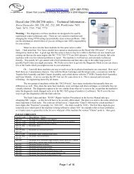
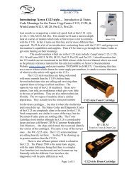
<strong>Profile</strong>: <strong>2510</strong> <strong>style</strong> (<strong>Xerox</strong> <strong>Engineering</strong> <strong>Copiers</strong>)<br />
<strong>2510</strong>, 2515, 2520<br />
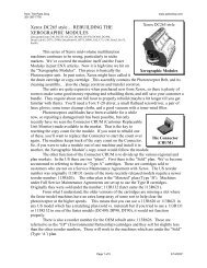
<strong>The</strong> engineering copiers are<br />
daunting at first glance… over 3 feet in<br />
length… 36 inch lamps… 36 inch rollers.<br />
<strong>Parts</strong> are far more expensive than similar<br />
parts for their smaller 8 ½ x 11 copier<br />
cousins. <strong>The</strong>y can be impressive and a bit<br />
discouraging if you’ve never worked on them before. In actuality these machines are<br />
relatively simple analog copiers. Of the folks I’ve spoken to… most techs who try fixing<br />
them wind up liking them. Most tech companies (including the OEM) use a different,<br />
more lucrative, service call rate when working on the engineering copiers. This is partly<br />
because it requires a tech with some specialized knowledge to work on these (not<br />
everyone wants to learn them considering how few there are compared to the smaller<br />
copiers).<br />
<strong>The</strong>re are a few important tips which you’ll want to be aware of… pitfalls to<br />
avoid and such. We’ll also go through a list of the Status Codes and what each of them<br />
means. <strong>The</strong>n we’ll talk a bit about getting into and using the Diagnostics.<br />
Here’s a quick list of what you should be aware of… we’ll talk in more detail about a few<br />
of these concerns below.<br />
Important Precautions & Tips:<br />
• Always remove the Fuser Lamp before removing the Fuser.<br />
• If you need to run the Main Motor from diagnostics… always turn on the cooling fans<br />
& fuser for 2 minutes first.<br />
• When running tests on the exposure lamp or high voltage, turn on the Main Motor<br />
first to avoid damaging the drum.<br />
• When installing a new Fuser Roll, oil the roller thoroughly.<br />
• Make a habit of checking the Oil Pads whenever you visit the machine to make sure<br />
the fuser doesn’t run out of lubricant.<br />
• While these machines are relatively simple to disassemble… count on having two<br />
people present. <strong>The</strong> modules are so bulky that one person handling them alone can be<br />
awkward to say the least.<br />
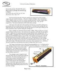
Removing the Fuser Lamp before removing the fuser is pretty critical… a 3 foot<br />
long lamp really does not need much of an excuse to break. <strong>The</strong> fuser is too bulky to<br />
handle without having an extremely high risk of snapping off the end of the lamp by<br />
accident. It’s an all-too-common and rather expensive mistake.<br />
When you are running diagnostic procedures, you need to do things in sequence<br />
to make sure you don’t damage anything. To some degree, these are common sense<br />
precautions… You must first turn on the cooling fans and then the fuser before you run<br />
the Main Motor. This is because room temperature fuser oil can seize up the fuser and<br />
cause gears to break. Whenever you run a high voltage test, the Main Motor must first be
<strong>The</strong> <strong>Parts</strong> <strong>Drop</strong> 201-387-7776 www.partsdrop.com<br />
running to make sure that the drum is moving (otherwise the voltages can damage the<br />
drum).<br />
<strong>The</strong> stuff about the lubrication of the fuser is also very important… I’ve been told<br />
that this machine is quite reliable, so long as someone is keeping an eye on the<br />
lubrication not running out. <strong>The</strong>se machines use a few versions of lubrication systems.<br />
If you are going to order new Oil Pads or Fuser Wicks… you’ll need figure out which<br />
version of the fuser oil dispenser your machine has in it. One version has a wick which is<br />
attached to a metal piece (glued on)… the other version has a removable wick. <strong>The</strong> “Oil<br />
Pad” serves as the reservoir for the fuser oil… new pads come prelubed.<br />
Following are the Status Codes. <strong>The</strong>se apply for the <strong>2510</strong>, 2515 and 2520 models.<br />
STATUS CODES:<br />
• A Document was inserted before copy paper was registered.<br />
To clear: Remove document, press ‘Start’, wait for ‘Ready’ to come on.<br />
• b Control PWB failure<br />
• b (flashing) Reset Non-Volatile Memory (NVM)<br />
• C Transport Cover open… or Upper Rear Cover is off.<br />
• E Paper Path Jam.<br />
• F Fuser problem.<br />
• H Foreign accessory problem.<br />
• J (Low Toner Light not Lit): Excessive toner concentration.<br />
• J (Low Toner Light Lit): Insufficient toner concentration.<br />
• U Total Count Meter is disconnected.<br />
• L9 to L0 Copier is warming up.<br />
• Constant P Copier is in the power saver mode.<br />
• Constant L9 or L8 Copier does not warm up.<br />
Copy Quality problems? First make sure the paper the customer is using is fresh<br />
(wet paper can cause poor fusing, deletion areas and other copy quality problems). If<br />
there are smears or wrinkles or poor fusing, you’ll want to make sure that the Fuser<br />
Roller is clean and lubricated… and that the Pressure plate (they call the material on it the<br />
“Fabric Guide”) is in good condition (wrinkles or damage to the fabric guide can cause<br />
problems for sure). Light copies overall may be caused by the developer being worn out.<br />
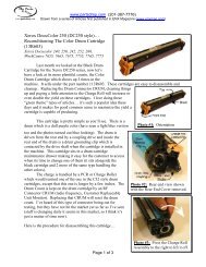
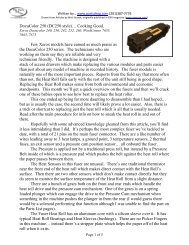
If you are having Toner Dispensing problems… the <strong>2510</strong> uses an “Arm” with a little<br />
metal adjustment lever on it which turns the toner cartridge around and around. <strong>The</strong> 2515<br />
and 2520 use a solenoid to activate the toner dispense arm. You’ll also want to make<br />
sure that the Toner cartridge holder clip is in place (a small green clip which goes at the<br />
end of the cartridge where it slides in). If that clip is missing, problems with toner<br />
dispensing will result.<br />
<strong>The</strong> Diagnostic Mode is the way to test components and adjust some of the<br />
memory settings.<br />
Entering Diagnostics:<br />
<strong>2510</strong>: Press & hold the ‘Copy Output’ button while powering up.<br />
2515/2520: Press & hold the ‘Bond’ and ‘Film’ buttons while powering up.
<strong>The</strong> <strong>Parts</strong> <strong>Drop</strong> 201-387-7776 www.partsdrop.com<br />
Once diagnostics is entered, the display will light up & then after 3 seconds, the lamps<br />
will turn off & the current software revision level will be displayed as the letter L and a<br />
number… then a ‘0’ will be displayed.<br />
Use the Copy Contrast UP & DOWN buttons to select the test you want to run.<br />
Exiting Diagnostics: Press the ‘Stop’ button.<br />
Once in Diagnostics, you can select a test by scrolling through the possibilities<br />
using the Copy Contrast Up or Down buttons. To test the Motion Sensor, you would<br />
select the “Top Segment” of the 7 segment display and then press ‘Start’. If you were to<br />
then manually turn the Motion Sensor, you’d see an LED on the display turn off and on<br />
as the machine sees the signal hi and low. <strong>The</strong> Motion Sensor is a wheel which turns<br />
when the copy paper is moving through the machine… it pulses as it turns. If the signal<br />
becomes steady (high or low) during the copy cycle, the machine calls an “E” code to<br />
indicate a paper jam. If you wanted to test the Document Sensor, you’d select the “Top<br />
Right Segment” of the 7 segment display and then press ‘Start’. <strong>The</strong>n if you were to<br />
manually actuate and deactuate that switch, the LED would again turn on and off.<br />
<strong>The</strong> Registration Adjustment works in a similar way as well. For that adjustment, you’d<br />
want to select “7” followed by ‘Start’. <strong>The</strong>n you’d use the Copy Contrast Up and Down<br />
buttons to change the setting. (5 is the default with the range being from 1 to 9). <strong>The</strong><br />
Fuser Temperature can also be adjusted in this way, except that you’d use the ‘0’instead<br />
of the ‘7’.<br />
To reset the NVM (non volatile memory) as would be necessary to do if you had a<br />
flashing ‘b’ Status Code… select the “Lower Right Segment” of the 7 segment display<br />
and press ‘Start’.<br />
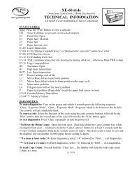
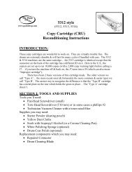
<strong>The</strong> Precharge / Detack, Charge, & Transfer are adjustable by their respective<br />
VR’s on the High Voltage Power Supply. As is always the case, make sure to note the<br />
position of the VR’s before you start turning them so that you can return things to where<br />
they were if you need to. <strong>The</strong>re are two versions of the Power Supply as shown in the<br />
illustrations below.<br />
That should be enough information to get you started in<br />
the right direction… I hoped I’ve piqued some of your<br />
interest out there! <strong>The</strong> Service Manuals for these can be<br />
purchased from <strong>Xerox</strong>® on their documentation website<br />
www.xdss.com. Gary Cox has also written a “Handi-<br />
Guide” which covers the diagnostic info specifically for<br />
the <strong>2510</strong> model.