Frigodrink Service manual - Ugolini
Frigodrink Service manual - Ugolini
Frigodrink Service manual - Ugolini

Create successful ePaper yourself
Turn your PDF publications into a flip-book with our unique Google optimized e-Paper software.
side of the copper tubing since the refrigerant gas is heavier<br />
than air. Where copper tubing is protected by an insulating<br />
jacket, check for leaks at both ends of each jacket section.<br />
.<br />
figure 8)<br />
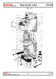
figure 7<br />
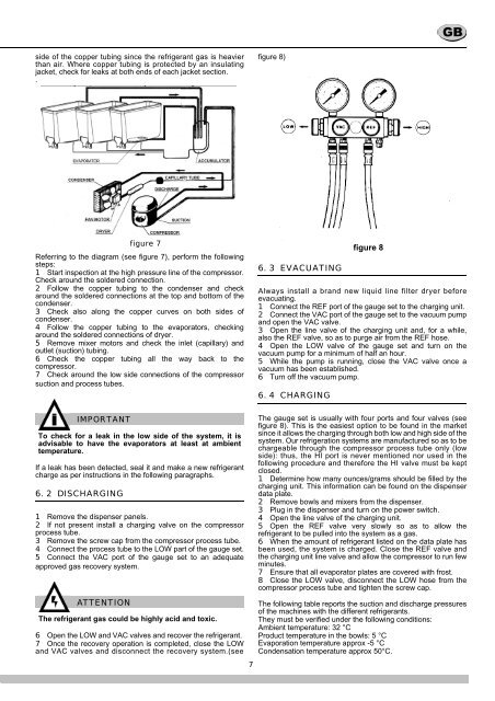
Referring to the diagram (see figure 7), perform the following<br />
steps:<br />
1 Start inspection at the high pressure line of the compressor.<br />
Check around the soldered connection.<br />
2 Follow the copper tubing to the condenser and check<br />
around the soldered connections at the top and bottom of the<br />
condenser.<br />
3 Check also along the copper curves on both sides of<br />
condenser.<br />
4 Follow the copper tubing to the evaporators, checking<br />
around the soldered connections of dryer.<br />
5 Remove mixer motors and check the inlet (capillary) and<br />
outlet (suction) tubing.<br />
6 Check the copper tubing all the way back to the<br />
compressor.<br />
7 Check around the low side connections of the compressor<br />
suction and process tubes.<br />
6. 3 EVACUATING<br />
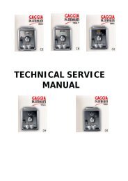
figure 8<br />
Always install a brand new liquid line filter dryer before<br />
evacuating.<br />
1 Connect the REF port of the gauge set to the charging unit.<br />
2 Connect the VAC port of the gauge set to the vacuum pump<br />
and open the VAC valve.<br />
3 Open the line valve of the charging unit and, for a while,<br />
also the REF valve, so as to purge air from the REF hose.<br />
4 Open the LOW valve of the gauge set and turn on the<br />
vacuum pump for a minimum of half an hour.<br />
5 While the pump is running, close the VAC valve once a<br />
vacuum has been established.<br />
6 Turn off the vacuum pump.<br />
6. 4 CHARGING<br />
IMPORTANT<br />
To check for a leak in the low side of the system, it is<br />
advisable to have the evaporators at least at ambient<br />
temperature.<br />
If a leak has been detected, seal it and make a new refrigerant<br />
charge as per instructions in the following paragraphs.<br />
6. 2 DISCHARGING<br />
1 Remove the dispenser panels.<br />
2 If not present install a charging valve on the compressor<br />
process tube.<br />
3 Remove the screw cap from the compressor process tube.<br />
4 Connect the process tube to the LOW part of the gauge set.<br />
5 Connect the VAC port of the gauge set to an adequate<br />
approved gas recovery system.<br />
ATTENTION<br />
The refrigerant gas could be highly acid and toxic.<br />
6 Open the LOW and VAC valves and recover the refrigerant.<br />
7 Once the recovery operation is completed, close the LOW<br />
and VAC valves and disconnect the recovery system.(see<br />
7<br />
The gauge set is usually with four ports and four valves (see<br />
figure 8). This is the easiest option to be found in the market<br />
since it allows the charging through both low and high side of the<br />
system. Our refrigeration systems are manufactured so as to be<br />
chargeable through the compressor process tube only (low<br />
side): thus, the HI port is never mentioned nor used in the<br />
following procedure and therefore the HI valve must be kept<br />
closed.<br />
1 Determine how many ounces/grams should be filled by the<br />
charging unit. This information can be found on the dispenser<br />
data plate.<br />
2 Remove bowls and mixers from the dispenser.<br />
3 Plug in the dispenser and turn on the power switch.<br />
4 Open the line valve of the charging unit.<br />
5 Open the REF valve very slowly so as to allow the<br />
refrigerant to be pulled into the system as a gas.<br />
6 When the amount of refrigerant listed on the data plate has<br />
been used, the system is charged. Close the REF valve and<br />
the charging unit line valve and allow the compressor to run few<br />
minutes.<br />
7 Ensure that all evaporator plates are covered with frost.<br />
8 Close the LOW valve, disconnect the LOW hose from the<br />
compressor process tube and tighten the screw cap.<br />
The following table reports the suction and discharge pressures<br />
of the machines with the different refrigerants.<br />
They must be verified under the following conditions:<br />
Ambient temperature: 32 °C<br />
Product temperature in the bowls: 5 °C<br />
Evaporation temperature approx -5 °C<br />
Condensation temperature approx 50°C.