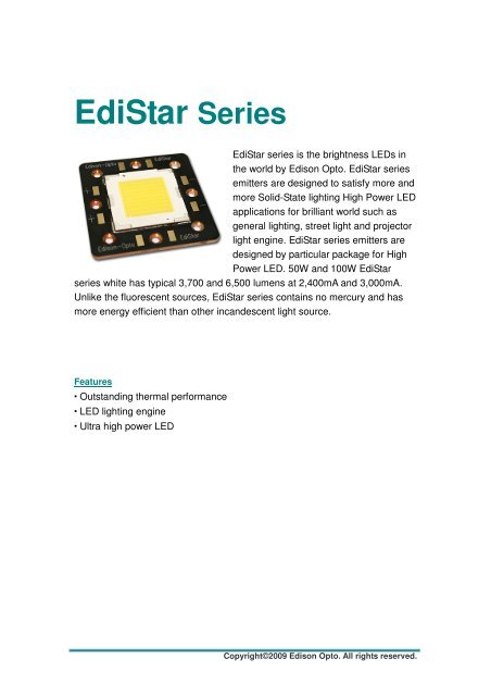
EdiStar Series - Perel
EdiStar Series - Perel
EdiStar Series - Perel

You also want an ePaper? Increase the reach of your titles
YUMPU automatically turns print PDFs into web optimized ePapers that Google loves.
<strong>EdiStar</strong> <strong>Series</strong><br />
<strong>EdiStar</strong> series is the brightness LEDs in<br />
the world by Edison Opto. <strong>EdiStar</strong> series<br />
emitters are designed to satisfy more and<br />
more Solid-State lighting High Power LED<br />
applications for brilliant world such as<br />
general lighting, street light and projector<br />
light engine. <strong>EdiStar</strong> series emitters are<br />
designed by particular package for High<br />
Power LED. 50W and 100W <strong>EdiStar</strong><br />
series white has typical 3,700 and 6,500 lumens at 2,400mA and 3,000mA.<br />
Unlike the fluorescent sources, <strong>EdiStar</strong> series contains no mercury and has<br />
more energy efficient than other incandescent light source.<br />
Features<br />
Outstanding thermal performance<br />
LED lighting engine<br />
Ultra high power LED<br />
Copyright©2009 Edison Opto. All rights reserved.
Table of Contents<br />
LED Package Dimensions and Polarity ...........................................................3<br />
LED Package with Star Dimension and Polarity...............................................5<br />
Absolute Maximum Ratings .............................................................................6<br />
Luminous Flux Characteristics.........................................................................7<br />
Forward Voltage Characteristics ......................................................................8<br />
JEDEC Information ..........................................................................................9<br />
Reliability Items and Failure Measures ..........................................................10<br />
Color Spectrum and Radiation Pattern........................................................... 11<br />
Product Soldering Instructions .......................................................................13<br />
Product Thermal Application Information .......................................................15<br />
Product Electrical Application Information......................................................21<br />
Product Packaging Information......................................................................26<br />
EDISON OPTO CORPORATION 1 Version:6
Product Nomenclature<br />
The following table describes the available color, power, and lens type. For more<br />
information on luminous flux and color, please refer to the Bin Group document.<br />
< Table 1 <strong>EdiStar</strong> series nomenclature ><br />
E N E W - 0 5 - 07 07 - A A - 1<br />
X1 X2 X3 X4 X5 X6 X7 X8 X9<br />
X1<br />
X2<br />
X3<br />
LED Item<br />
Type<br />
Emitter Color<br />
Code Type Code Type Code Type<br />
EN <strong>EdiStar</strong> E Emitter W White<br />
P Emitter + Driver<br />
H Neutral White<br />
S Emitter + Cu Star<br />
X Warm White<br />
C Emitter + Cu Star + Driver<br />
X4<br />
X5<br />
X6<br />
Power<br />
Circuit <strong>Series</strong><br />
Circuit Parallel<br />
Code Type Code Type Code Type<br />
0 5 50W 1~10 1~10 <strong>Series</strong> 1~10 1~10 Parallel<br />
1 0 100W<br />
X7<br />
X8<br />
X9<br />
Material<br />
Phosphor<br />
Substraes<br />
Code Type Code Type Code Type<br />
-- -- -- --<br />
1 --<br />
Environmental Compliance<br />
<strong>EdiStar</strong> series is compliant to the Restriction of Hazardous Substances Directive or<br />
RoHS. The restricted materials including lead, mercury cadmium hexavalent<br />
chromium, polybrominated biphenyls (PBB) and polybrominated diphenyl ether<br />
(PBDE) are not used in <strong>EdiStar</strong> series to provide an environmentally friendly product<br />
to the customers.<br />
EDISON OPTO CORPORATION 2 Version:6
LED Package Dimensions and Polarity<br />
ENEW-05-0707-EB-1<br />
Top View<br />
Bottom View<br />
+<br />
-<br />
Positive<br />
Anode (+)<br />
Negative<br />
Cathode (-)<br />
Side View<br />
Circuitry<br />
+<br />
Silicone<br />
Pad<br />
-<br />
Substrate<br />
< Figure 1 <strong>EdiStar</strong> 50W series dimensions ><br />
Notes:<br />
1. All dimensions are in mm.<br />
2. The tolerance is ±0.35 mm<br />
3. It is strongly recommended that the temperature of substrate dose not exceed 55℃.<br />
EDISON OPTO CORPORATION 3 Version:6
ENEW-10-1010-EB-1<br />
+<br />
-<br />
Top View<br />
Bottom View<br />
Positive<br />
Anode (+)<br />
Negative<br />
Cathode (-)<br />
Side View<br />
Circuitry<br />
+<br />
Silicone<br />
Pad<br />
-<br />
Substrate<br />
< Figure 2 <strong>EdiStar</strong> 100W series dimensions ><br />
Notes:<br />
1. All dimensions are in mm.<br />
2. The tolerance is ±0.35 mm<br />
3. It is strongly recommended that the temperature of substrate dose not exceed 55℃.<br />
EDISON OPTO CORPORATION 4 Version:6
LED Package with Star Dimension and Polarity<br />
Copper Core PCB for SMT Type of <strong>EdiStar</strong> series<br />
ENSW-10-1010-EB-1<br />
Edison-Opto<br />
<strong>EdiStar</strong><br />
+<br />
-<br />
Edison-Opto<br />
<strong>EdiStar</strong><br />
Top View<br />
Side View<br />
<strong>EdiStar</strong><br />
Copper PCB<br />
Pad<br />
<br />
Notes:<br />
1. All dimensions are in mm.<br />
2. The tolerance is ±0.35 mm<br />
3. It is strongly recommended that the temperature of substrate does not exceed 55℃.<br />
EDISON OPTO CORPORATION 5 Version:6
℃<br />
℃<br />
Absolute Maximum Ratings<br />
The following table describes characteristics of <strong>EdiStar</strong> series.<br />
< Table 2 Absolute maximum ratings for <strong>EdiStar</strong> 50W and 100W series ><br />
Parameter Rating(50W) Unit Symbol<br />
DC Forward Current 2,400 mA I F<br />
Peak pulse current;(tp≦100µs, Duty cycle=0.25) 5,000 mA<br />
Reverse Voltage 35 V V R<br />
Forward Voltage 35 V V F<br />
Junction Temperature 125<br />
j<br />
Substrate Temperature 100<br />
Operating Temperature -30 ~ +60<br />
Storage Temperature -40 ~ +60 V<br />
ESD Sensitivity 500 V<br />
T<br />
Manual Soldering Time at 400℃(Max.) 5 Sec.<br />
Parameter Rating(100W) Unit Symbol<br />
DC Forward Current 3,000 mA I F<br />
Peak pulse current;(tp<br />
100µs, Duty cycle=0. 5,000 mA<br />
Reverse Voltage 35 V V R<br />
Forward Voltage 35 V V F<br />
Junction Temperature 125<br />
j<br />
Substrate Temperature 100<br />
≦ 25)<br />
Notes:<br />
Operating Temperature -30 ~ +60<br />
Storage Temperature -40 ~ +60 V<br />
ESD Sensitivity 500 V<br />
1. Proper current rating must be observed to maintain junction temperature below the<br />
maximum at all time.<br />
2. LEDs are not designed to be driven in reverse bias.<br />
3. tp: Pulse width time<br />
℃<br />
Manual Soldering Time at 400<br />
(Max.)<br />
Sec.<br />
T<br />
℃ 5<br />
EDISON OPTO CORPORATION 6 Version:6
The following table describes thermal resistance of <strong>EdiStar</strong> series.<br />
< Table 3 Temperature Coefficient of Forward Voltage & Thermal Resistance Junction to Case<br />
Characteristics at T J =25℃ for <strong>EdiStar</strong> series ><br />
Part Name<br />
Color<br />
△V F/△T<br />
Rθ J-B<br />
Typ. Unit Typ. Unit<br />
mV/℃<br />
ENEW-05-0707-EB-1 Cool White -2 0.75<br />
ENEH-05-0707- EE-1 Neutral White -2 0.75<br />
ENEX-05-0707- EE-1 Warm White -2 0.75<br />
ENEW-10-1010-EB-1 Cool White -2 0.75<br />
ENEH-10-1010- EE-1 Neutral White -2 0.75<br />
ENEX-10-1010- EE-1 Warm White -2 0.75<br />
℃/W<br />
℃/W<br />
℃/W<br />
℃/W<br />
℃/W<br />
℃/W<br />
Luminous Flux Characteristics<br />
The following table describes flux of <strong>EdiStar</strong> series emitters.<br />
< Table 4 Luminous flux characteristics at I F =2,400mA/3,000mA and T J for <strong>EdiStar</strong><br />
series ><br />
=25℃<br />
Part Name<br />
Color<br />
Flux<br />
Min. Typ. Max.<br />
Unit<br />
ENEW-05-0707-EB-1 Cool White -- 3,700 -- lm<br />
ENEH-05-0707-EE-1 Neutral White -- 2,600 -- lm<br />
ENEX-05-0707-EE-1 Warm White -- 2,300 -- lm<br />
ENEW-10-1010-EB-1 Cool White -- 6,500 -- lm<br />
ENEH-10-1010-EE-1 Neutral White -- 5,200 -- lm<br />
ENEX-10-1010-EE-1 Warm White -- 4,800 -- lm<br />
Note:<br />
Flux is measured with an accuracy of ± 10%.<br />
EDISON OPTO CORPORATION 7 Version:6
Forward Voltage Characteristics<br />
The following table describes forward voltage of <strong>EdiStar</strong> series.<br />
< Table 5 Forward voltage characteristics at I F =2,400mA/3,000mA and T J =25℃ for <strong>EdiStar</strong><br />
series ><br />
Part Name<br />
Color<br />
V F<br />
Min. Typ. Max.<br />
Unit<br />
ENEW-05-0707-EB-1 Cool White 22.0 24.5 27.5 V<br />
ENEH-05-0707-EE-1 Neutral White 22.0 24.5 27.5 V<br />
ENEX-05-0707-EE-1 Warm White 22.0 24.5 27.5 V<br />
ENEW-10-1010-EB-1 Cool White 30.0 33.0 36.0 V<br />
ENEH-10-1010-EE-1 Neutral White 30.0 33.0 36.0 V<br />
ENEX-10-1010-EE-1 Warm White 30.0 33.0 36.0 V<br />
Note:<br />
Forward Voltage is measured with an accuracy of ± 0.1V<br />
EDISON OPTO CORPORATION 8 Version:6
JEDEC Information<br />
JEDEC is used to determine what classification level should be used for initial<br />
reliability qualification. Once identified, the LEDs can be properly packaged, stored<br />
and handled to avoid subsequent thermal and mechanical damage during the<br />
assembly solder attachment and/or repair operation. The present moisture sensitivity<br />
standard contains six levels, the lower the level, the longer the devices floor life.<br />
<strong>EdiStar</strong> series is certified at level 4. This means <strong>EdiStar</strong> series has a floor life of 72<br />
hours before <strong>EdiStar</strong> series emitters need to re-baked.<br />
< Table 6 JEDEC characteristics at T J =25℃ for <strong>EdiStar</strong> series ><br />
Level<br />
Floor Life<br />
Soak Requirements<br />
Standard<br />
Accelerated Environment<br />
Time Conditions<br />
Time (hours) Conditions Time (hours) Conditions<br />
4 72hours<br />
30<br />
60% RH<br />
96 +5/-0 30℃ / 60% RH 20 +0.5/-0 60℃ / 60% RH<br />
Level<br />
Floor Life<br />
Time Condition Time(hours) Condition Time(hours) Condition<br />
1 Unlimited≦30℃/85% RH 168 +5/-0 85℃/85% RH<br />
≦℃ /<br />
Standard<br />
Soak Requirements<br />
Accelerated Equivalent<br />
2 1 year<br />
≦30℃/60% RH 168 +5/-0 85℃/60% RH<br />
2a 4 weeks≦30℃/60% RH 696 1 +5/-0 30℃/60% RH 120 +1/-0 60℃/60% RH<br />
3 168 hours≦30℃/60% RH 192 1 +5/-0 30℃/60% RH 40 +5/-0 60℃/60% RH<br />
4 72 hours≦30℃/60% RH 96 1 +5/-0 30℃/60% RH 20 +5/-0 60℃/60% RH<br />
5 48 hours≦30℃/60% RH 72 1 +5/-0 30℃/60% RH 15 +5/-0 60℃/60% RH<br />
5a 24 hours≦30℃/60% RH 48 1 +5/-0 30℃/60% RH 10 +5/-0 60℃/60% RH<br />
6<br />
Time on tabel<br />
(TOL)<br />
≦30℃/60% RH TOL 30℃/60% RH<br />
Note:<br />
The standard soak time includes a default value of 24 hours for semiconductor<br />
manufacturer’s exposure time (MET) between bake and bag, and includes the maximum<br />
time allowed out of the bag at the distributor’s facility.<br />
EDISON OPTO CORPORATION 9 Version:6
Reliability Items and Failure Measures<br />
Reliability test<br />
The following table describes operating life, mechanical, and environmental tests<br />
performed on <strong>EdiStar</strong> series package.<br />
< Table 7 Reliability Items and Conditions ><br />
Stress Test<br />
Stress Conditions<br />
Stress<br />
Duration<br />
Failure Criteria<br />
Room Temperature Operating Life 25℃, I F = I F Max DC current 1000 hours Note 1<br />
High Temperature High Humidity<br />
Storage Life<br />
85℃ / 85%RH 1000 hours<br />
Note 1<br />
Non-Operating Temperature Cycle -40℃/100℃ ,30 min dwell /
side-by-side comparison of multiple LEDs. Since each lighting installation commonly<br />
uses many high-power LEDs, white point stability is a point of concern for lighting<br />
designers. Typically, white high-power LEDs, created by combining blue LEDs with<br />
yellow (and sometimes red) phosphor, will shift towards blue over operational life. This<br />
shift can be accelerated by high temperatures and high drive currents. For example, a<br />
cool white (e.g., 6500K CCT) LED with a white point failure will typically appear light<br />
blue instead of white. In some high-power LEDs, this failure mode can occur after just<br />
1,000 hours of operational life.<br />
Just as with fluorescent light sources, all white high-power LEDs will experience shifts<br />
in white point over their operating lives. It is possible for the design of the phosphor<br />
and packaging systems to minimize these shifts and contain the shifts to be less than<br />
what is detectable by the human eye. As with catastrophic failures, parametric failures<br />
can be minimized by adhering to limits specified in <strong>EdiStar</strong> series documentation.<br />
Color Spectrum and Radiation Pattern<br />
100<br />
80<br />
Irel(%).<br />
60<br />
40<br />
20<br />
0<br />
400 425 450 475 500 525 550 575 600 625 650 675 700 725<br />
Wavelength(nm)<br />
< Figure 4 Cool White Color spectrum at T J =25 ℃for . <strong>EdiStar</strong> series ><br />
EDISON OPTO CORPORATION 11 Version:6
100<br />
80<br />
60<br />
Irel(%)<br />
40<br />
20<br />
0<br />
400 425 450 475 500 525 550 575 600 625 650 675 700 725 750 775<br />
Wavelength(nm)<br />
< Figure 5 Neutral White<br />
、Warm White Color spectrum at T J =25 ℃for . <strong>EdiStar</strong> series ><br />
< Figure 6 Angular at T J =25℃ for <strong>EdiStar</strong> series ><br />
EDISON OPTO CORPORATION 12 Version:6
Emission Angle Characteristics<br />
< Table 8 Emission angle characteristics at Tj=25℃ for <strong>EdiStar</strong> series><br />
Part Name<br />
Color<br />
2Θ½(Typ.)<br />
Lambertian<br />
Unit<br />
ENEW-05-0707-EB-1 Cool White 120 Deg.<br />
ENEH-05-0707-EE-1 Neutral White 120 Deg.<br />
ENEX-05-0707-EE-1 Warm White 120 Deg.<br />
ENEW-10-1010-EB-1 Cool White 120 Deg.<br />
ENEH-10-1010-EE-1 Neutral White 120 Deg.<br />
ENEX-10-1010-EE-1 Warm White 120 Deg.<br />
Correlated Color Temperature Characteristics T J=25℃<br />
< Table 9 Correlated Color Temperature Characteristics at T J for <strong>EdiStar</strong> series ><br />
=25℃<br />
Part Name<br />
Color<br />
Min.<br />
CCT<br />
Max.<br />
ENEW-05-0707-EB-1 Cool White 5,000 10,000 K<br />
ENEH-05-0707-EE-1 Neutral White 3,800 5,000 K<br />
ENEX-05-0707-EE-1 Warm White 2,670 3,800 K<br />
ENEW-10-1010-EB-1 Cool White 5,000 10,000 K<br />
ENEH-10-1010-EE-1 Neutral White 3,800 5,000 K<br />
ENEX-10-1010-EE-1 Warm White 2,670 3,800 K<br />
Unit<br />
Product Soldering Instructions<br />
The central circle pad at the bottom face of the package provides the main path for<br />
heat dissipation from the LED to the heatsink (heatsink contact).<br />
20.0<br />
Notes:<br />
20.0<br />
Solder Pad<br />
Solder Pad<br />
1. All dimensions are measured in mm.<br />
2. MCPCB material with a thermal<br />
conductivity greater than 3.0 W/mK.<br />
3. Please avoid touching the <strong>EdiStar</strong> center<br />
area during assembly processes .This may<br />
3.0<br />
3.0<br />
cause pollution or scratch on the <strong>EdiStar</strong>.<br />
< Figure 7 Pad dimensions ><br />
EDISON OPTO CORPORATION 13 Version:6
The choice of solder and the application method will dictate the specific amount of<br />
solder. For most consistent results, an automated dispensing system or a solder<br />
stencil printer is recommended.<br />
Positive results will be used solder thickness that results in 50µm. The lamp can be<br />
placed on the PCB simultaneously with any other required SMD devices and reflow<br />
completed in a single step. Automated pick-and-place tools are recommended.<br />
The central slug at the bottom face of the package provides the main path for heat<br />
dissipation from the LED to the heat sink (heat sink contact). A key feature of <strong>EdiStar</strong><br />
series emitters are an electrically neutral heat path that is separate from the LED’s<br />
electrical contacts. This electrically isolated thermal pad makes <strong>EdiStar</strong> series<br />
emitters perfect for use with either FR4 circuit boards with thermal via or with<br />
metal-core printed circuit boards (MCPCB).<br />
Recommend Solder Steps<br />
To prevent mechanical failure of LEDs in the soldering process, a carefully controlled<br />
pre-heat and post-cooling sequence is necessary. The heating rate in an IR furnace<br />
depends on the absorption coefficients of the material surfaces and on the ratio of the<br />
component’s mass to its irradiated surface. The temperature of parts in an IR furnace,<br />
with a mixture of radiation and convection, cannot be determined in advance.<br />
Temperature measurement may be performed by measuring the temperature of a<br />
specific component while it is being transported through the furnace. Influencing<br />
parameters on the internal temperature of the component are as follows:<br />
• Time and power<br />
• Mass of the component (for <strong>EdiStar</strong> series emitters on MCPCB this is very important)<br />
• Size of the component<br />
• Size of the printed circuit board<br />
• Absorption coefficient of the surfaces and MCPCB<br />
• Packing density<br />
Peak temperatures can vary greatly across the PC board during IR processes. The<br />
variables that contribute to this wide temperature range include the furnace type and<br />
the size, mass and relative location of the components on the board. Profiles must be<br />
carefully tested to determine the hottest and coolest points on the board. The hottest<br />
and coolest points should fall within the recommended temperatures. The profile of<br />
the reflow system should be based on design needs, the selected solder system and<br />
the solder-paste manufacturer’s recommended reflow profile.<br />
EDISON OPTO CORPORATION 14 Version:6
Product Thermal Application Information<br />
Thermal grease should be evenly speeded with a thickness <br />
Note:<br />
<strong>EdiStar</strong> series emitter will generate ultra high thermal power, therefore its need a<br />
great-design heatsink to dissipate heat.<br />
EDISON OPTO CORPORATION 15 Version:6
Suggested Adhesive for Selection(such as thermal grease)<br />
Ease of use<br />
Non-solvent, One-part<br />
Fast tack free<br />
3 minutes at 25 o C<br />
No corrosion<br />
Alcohol type of room temperature vulcanization (RTV)<br />
Low volatility<br />
Low weight loss of silicone volatiles<br />
Adhesion<br />
Excellent adhesion to most materials without use of a primer<br />
Dielectric properties<br />
Cured rubber exhibits good dielectric properties<br />
Excellent thermal stability and cold resistance<br />
Cured rubber provides wide service temperature range<br />
< Table 10 Specification for adhesive properties ><br />
Specification<br />
Suggested Properties<br />
Take-free time<br />
3~10 minutes<br />
Specific gravity < 3 g/cm 2<br />
Thermal conductivity<br />
Rth in using<br />
> 2.5 W/mK<br />
< 1.8 o C/W<br />
Volume resistance > 1x10 14<br />
Lap shear adhesion strength > 200 N/ cm 2<br />
Tensile strength<br />
> 4 Mpa<br />
EDISON OPTO CORPORATION 16 Version:6
Recommended heat sink and attachment<br />
The function of cover (clip) is<br />
used to fix and force <strong>EdiStar</strong><br />
and heatsink to prevent the<br />
small gaps generate<br />
between the bottom surface<br />
of <strong>EdiStar</strong> and the top<br />
surface of heat sink.<br />
The forced area is the edge of the<br />
<strong>EdiStar</strong> (outside the shaded<br />
emitting area).<br />
The applied force on the <strong>EdiStar</strong><br />
should not exceed 3kgf/cm 2 .<br />
Gap<br />
<strong>EdiStar</strong><br />
Heat sink<br />
Without the applied force on<br />
<strong>EdiStar</strong>, the gap between <strong>EdiStar</strong><br />
and heat sink will be filled with<br />
air. The thermal path would be<br />
affected such that the thermal<br />
resistance between the medium<br />
will increase.<br />
< Figure 9 Heatsink and attachment ><br />
EDISON OPTO CORPORATION 17 Version:6
Example for Thermal Management<br />
Example 1<br />
Mechanical Design<br />
< Figure 10 Thermal heatsink design example 1 ><br />
Thermal simulation data<br />
Tmin (℃) Tmax (℃) Tavg (℃)<br />
Chip 85.9 90.5 88.36<br />
Slug 81.4 89.7 84.5<br />
Base 65.8 88.1 73.8<br />
Fin 56.1 84.8 66<br />
< Figure 11 50W Thermal simulation temperature example 1 ><br />
EDISON OPTO CORPORATION 18 Version:6
Example 2<br />
Mechanical Design<br />
Dimension: 170x130x100 mm<br />
Surface area: 4,800cm 2<br />
Use copper plate, heat pipe and fin<br />
for the thermal module.<br />
It can be more efficient to dissipate<br />
the LED generated heat<br />
< Figure 12 Thermal heatsink design example 2><br />
Thermal simulation data<br />
Tmax (℃) Tavg (℃)<br />
Chip 68 65<br />
Base 64 62<br />
Fin 60 50<br />
< Figure 13 50W Thermal simulation temperature example 2><br />
EDISON OPTO CORPORATION 19 Version:6
Example 3<br />
Design using extruded heatsink<br />
Aluminum alloy 6063 is used for the thermal simulation. It is the common material<br />
used for extrusion heatsink. The specifications and parameters serve as design<br />
reference and are conditioned in the most ideally free convection environment.<br />
Result would vary if the extruded heatsink is placed in an enclosed environment<br />
under different ambient temperature.<br />
65,000<br />
Thermal Management for Extruded Aluminum under free convection<br />
(T A =25℃; T HS =60℃)<br />
60,000<br />
55,000<br />
50,000<br />
45,000<br />
Surface Area (cm2)<br />
40,000<br />
35,000<br />
30,000<br />
25,000<br />
20,000<br />
15,000<br />
10,000<br />
5,000<br />
0<br />
0 5 10 15 20 25 30 35 40 45 50 55 60 65 70 75 80 85 90 95 100 105 110<br />
Operating Power (W)<br />
< Figure 14 Min. surface area for extrusion heatsink><br />
EDISON OPTO CORPORATION 20 Version:6
Product Electrical Application Information<br />
Electrical Application<br />
Following graphs and descriptions show how to connect LED or LED module and plug<br />
to AC outlet.<br />
Step1: Connect the wires of LED Module to the DC output of the driver.<br />
<br />
Step2: Plug the driver to AC outlet.<br />
<br />
Caution: Never plug the driver to AC outlet before the LED Module is properly<br />
connected as this may generate transient voltage damage the LEDs permanently with<br />
a short or open circuit.<br />
EDISON OPTO CORPORATION 21 Version:6
Recommended driver<br />
Part No.: EP-C50C-2400<br />
DC Output Forward Voltage: 18~36V<br />
Output Current: 2.4A (constant current)<br />
Made by High Perfection<br />
< Figure 17 Recommended driver specifications ><br />
EDISON OPTO CORPORATION 22 Version:6
Product Outlines (HS LP1090 series)<br />
< Figure 18 Recommended driver dimensions ><br />
EDISON OPTO CORPORATION 23 Version:6
Recommended driver<br />
Part No.: CLG-150-36-A<br />
DC Output Forward Voltage: 27~36V<br />
Output Current: 4.2A (constant current)<br />
< Figure 19 Recommended driver specifications ><br />
EDISON OPTO CORPORATION 24 Version:6
Product Outlines (CLG-150-36-A )<br />
< Figure 20 Recommended driver dimensions ><br />
EDISON OPTO CORPORATION 25 Version:6
Product Packaging Information<br />
Package Specifications<br />
< Figure 21 PP box dimensions><br />
Notes:<br />
1. All dimensions are in mm.<br />
2. Tolerance: ±0.2mm<br />
EPE<br />
EPE with 20 cavities<br />
Outer Box<br />
< Figure 22 Outer box and EPE package><br />
< Table 11 Package dimensions and quantity ><br />
Item Quantity Dimensions(mm)<br />
PP Box 1 pc 52*43*8<br />
Outer box 20 PP boxes 240*170*90<br />
EDISON OPTO CORPORATION 26 Version:6